Extractive Metallurgy of Copper 4th ed. - W. Davenport_ et. al. (2002) WW Part 14 pptx
Bạn đang xem bản rút gọn của tài liệu. Xem và tải ngay bản đầy đủ của tài liệu tại đây (577.88 KB, 30 trang )
CHAPTER
22
Melting and Casting
About 95% of the copper currently produced in the United States has existed as
cathode copper at some time during its processing (Edelstein,
2000).
The
cathodes are produced by electrorefining pyrometallurgical anodes (from
ore
and
scrap) and by electrowinning copper leached from 'oxide' and chalcocite ores.
To
make it useful, this copper must be melted, alloyed as needed, cast and
fabricated.
Much of the fabrication process for copper and its alloys
is
beyond the scope
of
this book;
see
Joseph (1999) for more information. However, melting and
casting are often the last steps in a copper smelter or refinery. A discussion
of
these processes is, therefore, in order.
22.1
Product Grades and
Quality
The choice of melting and casting technology
is
defined by:
(a) the quality of the input copper
(b) the required chemistry of the desired product
(c) the type
of
final product, e.g. wire or tube.
Table
22.1
lists the
copper
cathode
impurity limits specified by various national
standards (Joseph, 1999;
ASTM
B115-00).
Customers usually require purer
coppcr than in these specifications. Fortunately, recent adoption of stainless
steel cathodes for electrorefining and electrowinning has improved cathode
purity to match these customer requirements.
The tightest impurity limits in copper cathode are for selenium, tellurium and
bismuth. All three of these elements are nearly insoluble in solid copper. They
form distinct grain boundary phases upon casting and solidification.
361
368
Extractive Metallurgv
of
Copper
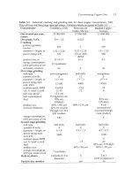
Table
22.1.
Upper impurity limits for copper cathodes as specified in the United States,
Great Britain and Chile (IWCC). Impurity limits specified for the Southwire Continuous
Rod (SCR) systems are also shown. (ASTM
=
American Society for Testing and
Materials; BS
=
British Standards; ppm =parts per million.)
IWCC
SCR (Southwire) Classifica-
1978
Element Grade
1
Grade 2 Grade Class
I
Class
2
Class
3
%
Cu+Ag
99.95
Se
bpm)
2
10
2
2
4
8
10
Te
(PPm)
2
5 2
2
0.5
1
2
Bi (ppm)
1
3
2
2
0.5
1
2
Bi+Se+Te (ppm)
3
3 3
Sb
(PPm)
4
15
4
4
0.5 0.1 2
Pb
bpm) 5
40
5 5
4
8 12
As (ppm)
5
15
5
5 0.5
0.1
2
BSEN
High
tion
System
ASTM
B-I15
Fe bpm)
10
25
10
10 10
20 30
Ni kpm) 10 20
10
20
30
Sn (ppm) 5 10
s
bpm)
15 25
15
15
Ag (pP4 25
70
25 25 0.5
10
30
co @pm)
3
5
10
Mn (pPd
3
5 15
Zn (ppm) 5 20 15
Total (ppm) 65
65
65
Selenium and tellurium
form
CuzSe and Cu2Te, while bismuth exists as pure Bi
(Zaheer, 1995). These phases are brittle and cause rod cracking and poor
drawability.
The Unified Numbering System currently recognizes about 35 grades
of
wrought
'coppers' (99.3% Cu
or
better) and six grades
of
cast coppers (Joseph, 1999).
Several
of
these coppers
are
alloyed with small amounts
of
phosphorus to
combine
with
oxygen when they are being welded.
Unalloyed coppers can be divided into
two
general classes. The first is
tough
pitch
copper, which purposefully contains
-250
ppm dissolved oxygen (Table
22.2;
ASTM B49-98; Feyaerts
et
al.,
1996).
Dissolving oxygen in molten copper accomplishes
two
goals. The first is
Melting and Casting
369
Table
22.2.
Upper impurity limit specifications
for
tough
pitch
copper in the United
States and Great Britain. (CDA
=
Copper Development Association; ASTM
=
American
Society for Testing and Materials; BS
=
British Standards; ppm
=
parts per million.)
CDA CDA ASTM BS
Cu-ETP-1 CU-ETP-2 B2 16-97 1038
Element (Grade
1)
(Grade
2)
%Cu (min.) 99.95 99.90 99.88 99.85
Ag (PPm) 25
As
(PPm) 05 120 0200
Sb
(PPW 04
030 0050
Bi @pm) 02 005
030
0030
Fe bpm) 10
0100
Pb (PPm)
05 050 040
0100
0
QJpm)
60 060 550 1000
Ni
@pm) 500 0500
Se bpm) 02 250 0300
s
@pm) 15
Te bpm) 02
Sn @pm) 0100
Total (ppm) 65 300
removal of inadvertently absorbed hydrogen during melting by the reaction:
(22.1).
This reduces the amount of porosity created by HlO(g) formation during casting
and welding.
The second is reaction of the oxygen with metallic impurities, precipitating them
as oxides at grain boundaries during solidification. These oxide precipitates
have
a
smaller adverse effect on drawability than compounds which would form
if oxygen were not present.
Most copper
is
cast and fabricated
s
tough
pitch.
impurities are shown
in
Table
22.2.
Specified limits for its
The second class of pure coppers are the
oxygen
free
(oxygen free copper
[OFC]
or oxygen free high conductivity copper
[OFHC])
grades. The amount
of
370
Extractive Metallurgy
of
Copper
oxygen in these grades is
so
low that no visible amount of
CuzO
is present in the
solid copper microstructure. The maximum permissible oxygen level in OFC is
10
ppm. In the best grades
it
is
only
5
ppm (ASTM B49-98; Nogami
et
al.,
1993).
Because
no
Cu20
is generated in the grain boundaries, the electrical conductivity
of OFC is higher than that
of
tough pitch copper.
As
a result, OFC is primarily
used for demanding electrical applications, such as bus tube and wave guides
(Joseph, 1999).
Specific numbers are unavailable, but the fraction
of
copper sold as
OFC
is
not
large. Koshiba
et
al. (2000) and the Copper Development Association (2001)
estimate that OFC accounts for less than
two
percent of total copper use.
Table
22.3.
U.S
copper processing
in
1999, kilotonnes
(Copper
Development Association, 2001).
Processing Facility
Wire
rod
mills
2259.6
Brass
mills 1878.2
Foundaries
167.3
Powder plants
18.1
Other
82.8
Copper processed
in
1999,
kilotonnes
22.2
Melting
Technology
22.2.1
Furnace
types
Table 22.3 shows the 1999 distribution of copper in the
US.
by type of
processing plant (Copper Development Association, 200
1).
Over half of copper
production is drawn into copper wire, a fraction which remained largely
unchanged in the 1990's. Also, about half of the 'brass mill product' shown in
Table 22.3 is unalloyed copper. It is mostly fabricated into pipe and tube.
As
a
result, most current melting and casting technology produces (i) copper rod
for drawing into wire
or
(ii) billets for extrusion to pipe and tube. The vast
majority of this copper is tough pitch.
Most tough pitch copper is produced from cathode in Asarco type shaft furnaces,
Fig. 22.1, Table 22.4. Ninety-five Asarco furnaces were operating in 1995,
processing about half the world's copper (Hugens and DeBord, 1995).
Melting and Casting
PB!
U
Prsmlx
Tunnel-
Burners.
8
per
Row
JI
Sillcon
Cnrblde
Refractory
Caatable
retracttry
371
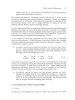
Fig.
22.1.
Asarco shaft fkmace for melting cathodes. Descending cathodes are melted
by
ascending combustion gases. Table 22.4 gives industrial operating data
372
Extractive
Metallurg),
of
Copper
Table
22.4.
Operating details
of
Asarco cathode melting shaft furnaces, 2001.
Melting plant
Nexans Phelps Dodge Norddeutsche Palabora
Canada Refinery Affnerie Mining
Montreal
El
Paso,
U.S.
Germany South Africa
Inputs
Molten copper
destination
Melting
rate,
tonnes of
copper per hour
Feed system
Furnace details,
m
height, taphole
to charge
floor
inside
diameter
at charge floor
inside
diameter
at taphole
Burner details
number
of burners
rows
of
burners
fuel
combustion
rate,
Nm3/hour
Nm3 of natural
gas burnt
per tonne
of
copper melted
Refractory life,
tonnes of copper
above burners
below burners
cathodes and
'runaround'
scrap rod
Hazelett
caster
&
rod mill
48
skip hoist
13
1.7
1.3
23
3
natural gas
1.9 giga-
joules
50G
000
250
000
cathodcs
Hazelett
caster
&
rod mill
75
elevator with
automatic trip
12.2
1.75
1.37
32
4
natural gas
2400
1.8
giga-
joules
cathodes
Southwire
caster
&
rod
mill
45
forklift truck
&
skip hoist
10
1.8
1.3
22
3
natural gas
1100
26
(furnace
only)
500
000
300
000
cathodes and
recycled
scrap
Southwire
caster
&
rod
mill
35
capacity,
21 operating
forklift truck
7.9
1.6
1.3
23
3
propane
50
x
IO6
kJ/h
a21.5
t
Cu/h
2.34 giga-
joules
3zkO.5 years
3h0.5 vears
Melting and Casting
313
The furnace operates counter currently, with rising hot hydrocarbon combustion
gas heating and melting descending copper cathodes. Natural gas is the usual
fuel, Table 22.4. The process is continuous.
An
important feature of the furnace is its burner. The burner uses a high-
velocity premix flame in a burner tile, accomplishing the premix within the
burner itself rather than in an external manifold. This design reduces accretions,
shortens downtime for cleaning and allows individual control of each burner.
Automatic burner control using
CO
analysis of the offgas is a common feature of
these furnaces (Schwarze, 1994). The flame is intended to generate a
moderately reducing atmosphere, resulting in molten metal with about 50 ppm
oxygen and 0.3-0.4 ppm hydrogen. Other impurity concentrations are largely
unaffected.
The most common feed to Asarco shaft furnaces is copper cathodes.
quality scrap is also occasionally melted.
High-
Lower-quality scrap is less suitable for Asarco shaft furnaces, which have no
refining ability. As a result, some produccrs use reverberatory furnaces as an
adjunct to their Asarco units (Schwarze, 1994; McCullough
et
al.,
1996). Metal
charged to these furnaces can be fire refined. This allows the furnaces to be used
for melting lower grade copper and scrap.
Another melting option is the induction furnace, either the channel
or
coreless
type (Schwarze, 1994). Induction furnaces are usually used to melt oxygen free
copper, since the absence of a combustion atmosphere prevents oxygen and
hydrogen from inadvertently being absorbed into the molten copper.
Feed to induction furnaces which produce oxygen free copper is limited to high-
quality cathode and scrap. Melting capacities are generally less than
two
tonnes
per hour (Vaidyanath, 1992; Nogami et
al.,
1993).
Molten copper from the above described melting furnaces flows into a holding
furnace before being directed to continuous casting. This ensures a steady
supply of molten copper to the casting machines.
Holding furnaces vary considerably in size and type, but they are usually
induction-heated to minimize hydrogen pickup from combustion gases. The
copper may also be covered with charcoal to minimize oxygen pickup.
Automation of the holding furnace to produce a steady flow of constant
temperature metal has become an important part
of
casting operations (Shook
and Shelton, 1999).
Ceramic filters have also begun to appear in copper casting plants, to remove
374
Extractive
Metallurgy
ofcopper
inclusions caused by erosion of the furnace refractories or precipitation of solid
impurities from the molten copper (Strand
et al.,
1994; Zaheer, 1995).
Introduction of multi-chamber induction furnaces is also a recent development
(Bebber and Phillips, 1998). The 'storage' chambers in these furnaces eliminate
the need for multiple holding furnaces.
22.2.2
Hydrogen and oxygen measurementkontrol
As previously mentioned, control
of
hydrogen and oxygen in molten copper is
critical. Oxygen is monitored one
of
two
ways. The first is Leco infrared
absorbance, which measures the amount of C02 generated when the oxygen in a
heated sample
of
copper reacts with admixed carbon black. This method
requires external sample preparation,
so
does not offer an immediate turnaround.
The second approach is an oxygen sensor, which is applied directly to the molten
copper. The electrode potential of the dissolved oxygen in the copper is
measured against a reference electrode in the sensor. This relative potential is
converted to an equivalent oxygen content in the metal at the measurement
temperature. Dion
et al.
(1995) have shown that the
two
methods yield similar
results. The amount of oxygen in the molten copper is controlled by adjusting
burner flames and by injecting compressed air into the copper, Table 22.5.
Hydrogen is more difficult to monitor and control. Analysis of solid samples is
usual practice (Strand
et
al.,
1994), but efforts have been made to adapt
aluminum industry technology
to
on-line measurement of hydrogen in molten
copper (Hugens, 1994).
Hydrogen pickup is minimized by melting the copper with oxidizing flames.
However, the molten copper always contains a small amount of hydrogen from
entrapped electrolyte in the cathode feed (Chia and Patel, 1992; Back
et
al.,
1993).
22.3
Casting
Machines
Casting machines can be divided into three main types:
(a) billet ('log') casting, for extrusion and drawing to tube, Fig. 22.2
(b) bar casting, for rolling to rod and drawing towire, Figs. 22.3, 22.4, Table
22.5
(c) strip casting, for rolling to sheet and forming of welded tube.
22.3.
I
Billet casting
Billet casting is usually performed in vertical direct-chill casters, such as that
Melting and Casting
315
shown in Fig.
22.2
(Nussbaum, 1973). Graphite-lined copper
or
graphite-
ceramic molds are used. Diameters up to
30
centimeters are cast (Hugens and
DeBord, 1995). Oscillation
of
the water-cooled molds (60-360 mid) improves
surface quality and prevents sticking in the mold.
Over the past decade, horizontal casters have begun to replace vertical billet
casters, due to their lower cost (Owen, 1990).
A
recent innovation is horizontal
continuous casting
of
hollow billets (Rantanen, 1995; Taylor, 1992). These
billets are rollcd directly to tube, eliminating the need for extrusion and piercing.
They give a low-cost, high quality product.
Fig.
22.2.
Continuous direct-chill
casting
machine
for
casting copper billet (Nussbaum,
1973).
Reprinted with permission
of
TMS.
376
Extractive
Melallurgy
of
Copper
22.3.2
Bar
and
rod casting
Copper bar
is
mostly cast in continuous wheel-and-band and twin-band casting
machines, Table 22.5 and Figs. 22.3 and
15.3.
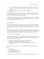
Figure 22.3 shows a Southwire wheel-and-band caster. Its key features are:
(a) a rotating copper-zirconium alloy rimmed wheel with a mold shape
machined into its circumferencc
(b) a cold-rolled steel band which moves in the same direction and at the
same speed as the wheel circumference.
Molten copper
is
poured from a 'pour pot' into the mold just as the steel band
joins the wheel to form the fourth side of the mold. The wheel and band move
together through water sprays as the copper solidifies. After
180-250"
of
rotation, the band moves off to an idler wheel and the solidified copper bar is
drawn away (under minimum tension) to a rolling mill. Pouring to bar
separation takes about 0.25 minutes (Adams and Sinha,
1990).
The cast bar is
removed at about 0.25
ds.
The Properzi casting machine is similar.
Extractor
Pinch
ROW
Cross section rim
mould
for
35
cm2
bar
Cast Copper
<-Band
Temeioner
_j
Presser
Wheel
Steel
Band
Fig.
22.3. Southwire casting machine
for
continuously casting copper bar (Adams and
Sinha,
1990).
The inset shows the cross-section
of
the rim mold.
Melting
and
Casting
3
77
The Hazelett twin-band caster is shown in Fig.
15.3
in its role as an anode-
casting machine. Molten copper is fed from a pour pot into the space between
two sloped moving steel bands. The bands are held apart by moving alloyed
copper dam blocks on each side, creating a mold cavity ranging between 5-15
cm in width and 5-10 cm in thickness. Both separations are adjustable, allowing
variable product size. Solidification times are similar to those
of
the Southwire
and Properzi machines (Strand
et
al.,
1994).
The three types of moving-band casting devices have several features in
common. All require lubrication of the bands and mold wheel or dam blocks,
using silicone oil or acetylene soot (Adams and Sinha, 1990). Leftover soot is
removed from the bands after each revolution, then reapplied. This ensures an
even lubricant thickness and a constant heat transfer rate.
Fig.
22.4.
System
for
controlling molten copper
level
in
Southwire continuous casting
machine
(Adams
and
Sinha,
1990).
Reprinted courtesy
TMS.
378
Extractive Metallurgy
of
Copper
Table
22.5.
Operating details
of
Hazelett and Southwire continuous casting machines,
2001,
Casting plant
Nexans Phelps Dodge
Norddeutsche Palabora
Canada Refinerv Affinerie Minim
Casting machine
Bar size, em
x
cm
Casting rate
of
this bar,
tonneslhour
Molten copper level
control in caster
Casting temp.,
OC
Bar temperature
leaving caster, OC
Target
0
in
copper, ppm
measurement
technique
control system
Wheel and band details
wheel diameter, m
rotation speed, rpm
rim materials
rim life, tonnes of cast
copper
band material
band life
lubrication
Hazelett
twin band
7x13
48
electromagnetic
pool level
measurement
1
I25
-950
250
Electro-nite cell
in launder;
Tempolab in
holding furnace;
Leco on rod
manual
Twin band details
caster length, m 3.7
band material low carbon steel
life
24 hours
lubrication oil
dam block material Si bronze
dam block life
100
000
tonnes
cast copper
Hazelett
twin band
7
x
13.2
63
electromagn-
etic pool level
measurement
1
I30
1015
250
Leco on rod
compressed
air injection
into molten
cu
3.7
titanium steel
1300
tonnes
cu
Union Carbide
Lb-300x oil
Cu with 1.7-
2% Ni
&
0.5-
0.9% Si
-300 hours
Southwire
wheel
&
band
5.8
x
11.7
45
X-ray
11
10-1
125
900
160-250
Leco
protective gas,
larger
or
smaller quan-
tity
3.05
1.33
Cu-Cr-Zr
100
000
cold rolled
steel
72 hours
Lubro 30 FM
Southwire
wheel &band
2.15
x
15
21.5
infrared scan-
ner
1100-1
130
890-930
180-250
Leco on rod
holding fur-
nace CO and
launder burner
co
2.44
1.8
Cu-Cr-Zr
45
000
steel
low split C
1000-1800
t
Cu per band
Thermia
B
(Shell)
Melting
and
Casting
379
The casters all use similar input metal temperatures, 11 10-1 130°C, Table 22.5.
All require smooth, low-turbulence metal feed into the mold cavity, to reduce
defects in the solidified cast bar. Lastly, all require steady metal levels in the
pour pot and mold.
Control of mold metal level is done automatically, Fig. 22.4. Metal level in the
mold cavity is measured electromagnetically (Hazelett)
or
with a television
camera (Southwire). It is controlled with a stainless-steel metering pin in the
pour pot.
Metal level in the pour pot is determined using a conductivity probe or load cell.
It is controlled by changing the tilt
of
the holding furnace which feeds
it
(Nogami
et
ul.,
1993; Shook and Shelton, 1999).
The temperature of the solidified copper departing the machine is controlled to
940- 101 5°C by varying casting machine cooling-water flow rate.
Common practice for copper cast in the Hazelett, Properzi and Southwire ma-
chines is direct feeding of the solidified bar into a rolling machine to give con-
tinuous production of copper rod. Southwire Continuous Rod and Hazelett
Contirod are prominent (Buch
et al.,
1992; Hugens and DeBord, 1995; Zaheer,
1995). Both systems produce up to
60
tonnes of 8-14 mm rod per hour, Table
22.5.
22.3.3
Oxygen
free
copper casting
The low oxygen and hydrogen content of oxygen free copper minimizes porosity
when this metal is cast. As a result, the rolling step which is used to
turn
tough
pitch copper bar into rod is not necessary. This has led to the development of
processes for direct casting
of
OFC copper rod. These include both horizontal
and vertical casting machines (Joseph, 1999).
Horizontal rod-casting machines use a graphite crucible and a submerged casting
die. They generally operate as multi-strand machines. Their capacities are
limited to about
0.6
tonnes per hour.
They cannot produce very small diameter
rod.
Upward vertical casting machines use a vacuum to draw metal into water-
cooled graphite-lined dies partially submerged in the molten copper. As it
freezes, the rod is mechanically drawn upward and coiled (Eklin, 1999;
Rautomead, 2000). It is about the same size as rolled rod.
22.3.4
Strip casting
The development of strip casting for copper and copper alloys parallels
380
Extractive
Metallurgy
of
Copper
developments in the steel industry, in that continuous processes are favored. The
newer the technology, the less rolling is required. One approach taken by small-
volume producers is to roll strip from the bar produced by a Hazelett caster
(Roller
et
al.,
1999). This can be combined with continuous tube rolling/welding
to make optimum use
of
the casting machine for a mix of products.
However, direct strip casting which avoids rolling is the goal. Current horizontal
casters can produce 'thick strip' (15-20 mm), which requires some rolling (Roller
and Reichelt, 1994). Development efforts are being made
to
develop 'thin-strip'
(5-12 mm) casting to avoid rolling completely.
22.4
Summary
The last step in copper extraction is melting and casting of electrorefined and
electrowon cathodes. The main products of this melting and casting are:
(a) continuous rectangular bar for rolling to rod and drawing to wire
(b) round billets ('logs') for extrusion and drawing to tube
(c)
flat strip for rolling to sheet and forming into welded tube.
The copper in these products is almost always 'tough pitch' copper, Le. cathode
copper into which -250 ppm oxygen has been dissolved during meltinghasting.
This dissolved oxygen:
(a) ensures a low level of hydrogen in the copper and thereby avoids steam
porosity during casting and welding
(b) ties up impurities as innocuous grain boundary oxide precipitates in the
cast copper.
The remainder
of
unalloyed copper production is in the form of oxygen free high
conductivity copper with
5
to
10
ppm dissolved oxygen. This copper is
expensive to produce
so
it is only used
for
the most demanding high conductivity
applications. It accounts for less than 2% of copper production.
These pure copper products account for about 70% of copper use.
remainder is used in the form
of
copper alloy, mainly brass and bronze.
The
The principal melting tool for cathodes is the Asarco shaft furnace.
thermally efficient and provides good oxygen-in-copper control.
copper is mainly cast:
It is
Its molten
(a) as rectangular bar in continuous wheel-and-band and twin-band casters
(b) as round billets ('logs') in horizontal and vertical direct chill casters.
Melting and Casting
381
The bar casters are especially efficient because their hot bar can be fed directly
into continuous rod-rolling machines.
The quality of cathode copper is tested severely by its performance during
casting, rolling and drawing to fine wire.
Copper for this use must have high
electrical conductivity, good drawability
and
good annealability. These
properties are all favored by maximum cathode purity.
Suggested Reading
Adams,
R.
and Sinha,
U.
(1990) Improving the quality
of
continuous copper rod.
Journal
of
Metals,
42(5),
3
1
34.
Hugens,
J.R.
and DeBord, M. (1995) Asarco shall melting and casting technologies '95. In
Copper 95-Cobre 95 Proceedings of the Third International Conference,
Vol.
IV
Pyrometallurgy
of
Copper,
ed. Chen, W.J., Diaz,
C.,
Luraschi, A. and Mackey, P.J., The
Metallurgical Society
of
CIM, Montreal, Canada,
133
146.
Joseph, G. (1999)
Copper:
Its
Trade, Manufacture,
Use
and Environmental Status,
ed.
Kundig,
K.J.A.,
ASM International, Materials Park, OH, 141 154; 193 217.
Schwarze, M. (1994) Furnace systems for continuous copper rod production.
Wire Industry,
61
(731), 741 743; 748.
References
Adams,
R.
and Sinha,
U.
(1990) Improving the quality of continuous copper rod.
Journal
of
Metals,
42
(5),
3
1
34.
American Society
for
Testing and Materials (1997) Standard specification
for
tough pitch
fire-refined copper
-
refinery shapes (B216-97). In
Annual
Book
of
Standards, Section
2,
Nonferrous Metal Products,
ASTM, Philadelphia, PA.
American Society for Testing and Materials (1998) Standard specification for copper rod
drawing stock for electrical purposes (B49-98). In
Annual
Book
of Standards, Section 2,
Nonferrous Metal Products,
ASTM, Philadelphia, PA.
American Society
for
Testing and Materials (2000) Standard specification
for
electrolytic
cathode copper (B115-00). In
Annual
Book
of
Standards, Section
2,
Nonferrous Metal
Products,
ASTM, Philadelphia, PA.
Back,
E.,
Paschen, P., Wallner,
J.
and Wobking,
H.
(1993) Decrease of hydrogen and
oxygen contents in phosphorus-free high conductivity copper prior to continuous casting.
BIIMs
138,22
26.
Bebber,
H.
and Phillips,
G.
(1998) Induction furnace technology for horizontal casting.
Metallurgia.
65,349 35
1.
382
Extractive Metallurgy
of
Copper
Buch, E., Siebel,
K.
and Berendes,
H.
(1992) Operational experience of newly developed
mini copper rod casting and rolling plants, CONTIROD system.
Wire,
42,
110
114.
Chia, E.H. and Patel, G.R. (1992) Copper rod and cathode quality as affected by hydrogen
and organic additives.
Wire
J.
Int.,
25
(1
I),
67 75.
Copper Development Association (2001) CDA’s annual data
’00.
www.copper.org
Dion,
J.L.,
Sastri,
V.S.
and Sahoo, M. (1995) Critical studies on determination of oxygen in
copper anodes.
Trans. Am. Foundtyman’s SOC.,
103,47 53.
Edelstein, D.E. (2000) Copper.
In
1999
Minerals Yearbook,
United States Geological
Survey,
Eklin,
L.
(1999) UF’CAST-near net shape casting of copper wire rod. In
1999
Con$
Proc. Wire Assoc. Inter.,
Wire Association International, Guilford, CT, 274 277.
Feyaerts, K., Huybrechts,
P.,
Schamp,
J.,
van Humbeeck,
J.
and Verlinden,
B.
(1996) The
effects of impurities on the recrystallization behavior of tough pitch hot rolled copper rod.
Wire
J.
Int.,
29
(1
I),
68 76.
Hugens,
J.R.
(1994) An apparatus
for
monitoring dissolved hydrogen in liquid copper. In
EPD Congress
1994,
ed. Warren, G.W., TMS, Warrendale, PA, 657 667.
Hugens, J.R. and DeBord,
M.
(1995) Asarco shaft melting and casting technologies
’95.
In
Copper 95-Cobre
95
Proceedings
of
the Third International Conference,
Vol.
IV
Pyrometallurgy
of
Copper,
ed. Chen, W.J., Diaz, C., Luraschi, A. and Mackey, P.J., The
Metallurgical Society of CIM, Montreal, Canada, 133 146.
Joseph, G. (1999)
Copper: Its Trade, Manufacture, Use and Environmental Status,
ed.
Kundig, K.J.A., ASM International, Materials Park,
OH,
141 154; 193 217.
Koshiba,
Y.,
Masui,
T.
and Iida,
N.
(2000) Mitsubishi Materials’ high performance oxygen
free copper and high performance alloys. In
Second
Int.
Con$ Processing Mater. Prop.,
ed.
Mishra, B. and Yamauchi,
C.,
TMS, Warrendale, PA,
101
104.
McCullough, T., Parglu, R. and Ebeling, C. (1996) Oxy-fuel copper melting for increased
productivity and process cnhancement. In
Gas Interactions in Nonferrous Metals
Processing,
ed. Saha, D., TMS, Warrendale, PA, 22
1
227.
Nogami, K., Hori, K. and Oshima, E. (1993) Continuous casting of Onahama oxygen-free
copper and alloys. In
First
Int.
Con$ Processing Mater. Prop.,
ed. Henein,
H.
and Oki, T.,
TMS, Warrendale, PA, 389 392.
Nussbaum, A.I. (1973) Fully and semi-continuous casting of copper and copper-base alloy
billets and slabs.
In
Continuous
Casting.
ed. Olen,
K.R.,
TMS, Warrendale, Pennsylvania,
73 91.
Owen, M. (1990) High-quality copper billet.
Tube
International,
9
(38), 273 277.
Melting and Casting
383
Rantanen, M. (1995) Cast and roll-new copper tube manufacturing technology from
Outokumpu. In
Copper 95-Cobre 95 Proceedings of the Third International Conference,
Vol.
I
Plenary Lectures, Economics, Applications and Fabrication of Copper,
ed.
Diaz,
C.,
Bokovay,
G.,
Lagos,
G.,
Larrivide,
H.
and Sahoo, M., The Metallurgical Society of CIM,
Montreal, Canada, 449 453.
Rautomead, Ltd.
(2000)
Copper rod and wire
~
an integrated approach towards optimum
quality.
Metallurgia,
61
(9), 24
25.
Rollel,
E.,
Kalkenings,
P.
and
Hausler,
K.11.
(1999)
Continuous
narrow strip production line
for welded copper tubes.
Tube International,
18,28 3
1.
Roller,
E.
and Reichelt, W. (1994) Strip casting of copper and copper alloys. In
Proc.
METEC Congress 94,
Vol.
1,
Verein Deutscher Eisenhiittenleute, Diisseldorf, Germany, 480
486.
Schwarze,
M.
(1994) Furnace systems for continuous copper rod production.
Wire Industry,
61
(73
I),
741 743; 748.
Shook, A.A. and Shelton, C.A. (1999) Improved rod plant level control with WAC. In
Copper 99-Cobre 99 Proceedings
of
the Fourth International Conference,
Vol.
I
Plenary
Lectures, Movement of Copper and Industry Outlook, Copper Applications and Fabrication,
ed. Eltringham, G.A., Piret,
N.L.
and Sahoo, M., TMS, Warrendale, PA, 293 302.
Strand,
C.I.,
Breitling, D. and DeBord, M. (1994) Quality control system
for
the
manufacture of copper
rod.
In
1994
Conf Proc. Wire Assoc. Inter.,
Wire Association
International, Guilford,
CT,
147
15
I.
Taylor,
J.
(1
992) Continuous casting of hollow copper billets.
TPQ,
3
(3), 42 47.
Vaidyanath, L.
R.
(1992) Producing copper
and
copper
alloy
tubes.
Tube Internatiorzal.
11
(48),
165
166.
Zaheer, T. (1995) Reduction of impurities in copper.
Wire Industry,
62
(742), 55
1
553
CHAPTER
23
Costs
of
Copper Production
This chapter:
(a) describes the investment and production costs of producing copper metal
from ore
(b) discusses
how
these costs are affected
by
such factors as ore grade,
process choice and inflation
(c) indicates where cost savings might be made in the future.
The discussion centers
on
mine, concentrator, smelter and refinery costs. Costs
of producing copper by IeacWsolvent
extractiodelectrowinning
and
from
scrap
are also discussed.
The cost data have been obtained from published information and personal
contacts in the copper industry. They have been obtained during
2001
and
2002
and are expressed in
2002
US.
dollars. The data are directly applicable to plants
in the
USA.
They are thought to be similar to costs in other parts of the world.
Investment and operating costs are significantly affected by inflation.
Fortunately,
U.S.
dollar inflation was low during the
1990’s
and early
2000’s, so
the cost
of
producing copper rose slowly.
This is confirmed by the
1982-2001
inflationary index for mining and milling
equipment, Fig.
23.1.
The basic equation for using this index
is:
(23.1)
Cost
(year
A)
-
Index
(year
A)
Cost
(yearB)
Index
(yearB)
-
(for identical equipment). Fig.
23.1
and Eqn.
23.1
show
that
1990’s
mining and
milling equipment costs rose less than
2%
per year.
385
386
Extractive Metallurgy
of
Copper
1100
1000
900
800
700
r
I
1982 1986 1990 1994 1998 2002
Year
Fig.
23.1.
Engineering,
2001).
Mining and milling equipment
cost
index from 1982
to
2001
(Chemical
Accuracy
of
the
cost
data
The investment and operating costs in this chapter are at the ‘study estimate’
level, which is equivalent to an accuracy of *30% (Bauman, 1964). Data with
this accuracy can be used to examine the economic feasibility
of
a project before
spending significant funds for piloting, market studies,
land surveys and
acquisition (Perry and Chilton, 1973).
23.1
Overall Investment Costs: Mine through Refinery
Table 23.1
lists ‘study estimate’ investment costs for a mine/concentrator/
smelterhefinery complex designcd to produce electrorefined cathodes from
0.75%
Cu ore. These costs are
for
a ‘green field’ (new) operation starting on a
virgin site with construction beginning January 1,2002.
The investment costs are expressed in terms
of
investment cost per annual tonne
of product copper. This is defined by the equation:
(23.2).
investment cost per annual
plant capacity,
tonnes of copper per year
plant cost
=
tonne of copper
This equation shows, for example, that the investment in an electrorefinery
Costs
of
Copper Production
387
which:
(a) costs
$500
per annual tonne of copper
(b) produces 200
000
tonnes of copper per year
will be:
$500
per annual
tonne of copper
200
000
tonnes
of copper per year
investment cost
=
or:
$100
x
lo6
Table 23.1 indicates that the fixed capital investment for a complex which
produces electrorefined copper from
0.75% Cu
ore is in the range of
$8500
per
annual tonne
of
copper.
To
this must be added working capital
to
cover the
initial operating expenses of the complex (about 10%
of
fixed capital
investment, Peters and Timmerhaus,
1968).
It means that a new mine/mill/
smelterhefinery complex which is to produce 200
000
tonnes of copper per year
will cost 41900
x
lo6.
23.1.1
Variation
in
investment
costs
Mine investment costs vary considerably between mining operations. This is
due to differences in ore grades, mine sizes, mining method, topography and
ground condition.
Underground mine development costs considerably more than open pit mine
development, per annual tonne of mined
ore.
This, and the high cost
of
operating underground explain why underground orebodies must contain higher
%
Cu
ore than open pit orebodies.
Table
23.1.
Copper extraction
investment
costs. Fixed investment costs for a copper
extraction complex, starting with
0.75%
Cu
ore. The costs are at the ‘study estimate’
level
of
accuracy. Cost effects of underground mining and ore grade are discussed
in
Section 23.1.1.
Facility
Fixed
investment cost
CWS.
Der
annual tonne
of
Cul
~ ~
Mine (open pit)
Concentrator
Smelter (Outokumpu flash furnace smelting/
converting), including sulfuric acid plant
Electrolytic refinery (excluding precious
metals refinery)
3000
2500
2500
500
Total
8500
388
Extractive Metallurgy
of
Copper
Ore grade has a direct effect on mine investment costs,
$
per annual tonne of
product copper. Consider (for example) two identical orebodies, one containing
0.5%
Cu
ore and the other 1% Cu ore.
Achievement of an identical annual
production of
Cu
requires that the
0.5%
Cu ore be mined at twice the rate of the
1
%
Cu
ore. This, in turn, requires:
(a) about twice as much plant and equipment (e.g. trucks)
(b) about twice as much investment.
The same is true for the concentrator
-
it will have to treat
0.5%
Cu ore twice as
fast as 1% Cu ore
-
to achieve the same annual production of Cu. This will
require about twice the amount of concentrator equipment and about twice the
investment.
Smelter investment costs, per annual tonne of copper production, are influenced
by
concentrate
grade rather than by ore grade. The higher the
%
Cu
in the
concentrate, the smaller the smelter (and smelter investment) for a given annual
production of copper. High Cu grade concentrates also minimize smelter
operating
costs (e.g. materials handling costs, fuel consumption costs, gas
handling costs) per tonne of copper.
Refinery investment costs are not much affected by
mine/concentrator/smelter
characteristics. This is because copper refineries treat 99.5%
Cu
anodes,
irrespective
of
the preceding processes.
23.1.2
Economic
sizes
ofplants
Mines can be economic at any size, depending upon the
Cu
grade
of
their ore.
Thus, copper mines are operating at production rates between 10
000
tonnes of
ore per day (a high Cu grade operation) to 100
000
tonnes per day (a large open-
pit low Cu grade operation,
EMJ,
1998).
Concentrators vary similarly. A new large concentrator unit typically consists
of
a semi-autogenous grinding mill, two ball mills and a flotation circuit. It
is
capable
of
treating
30
000
to
50
000
tonnes of ore per day (Dufresne,
2000;
EMJ,
1998). Larger concentrators consist of multiples of this basic
concentrating unit.
Smelters are almost always large because their minimum economic output is that
of
a single, fully used high intensity smelting furnace (e.g. flash furnace). These
furnaces typically smelt 1000 to
3000
tonnes of concentrate per day.
Copper refineries are usually sized to match the anode output of an adjacent
smelter. The advantage of one-smeltedone-refinery combination at the same site
is shared site facilities, particularly for anode casting and anode scrap re-melting.
Costs
ofCopper Production
389
A
few refineries treat the anodes from several smelters.
23.2
Overall Direct Operating
Costs:
Mine Through Refinery
Direct operating (‘cash’) costs (excluding depreciation, capital repayment and
income taxes) for
mining/concentrating/smelting/electrorefining
are given in
Table
23.2.
The table shows that the direct operating costs for the major steps
are, in descending order, concentration and smelting (about equal); open pit
mining; electrorefining; and sales and distribution. Overall direct operating costs
for extraction are
-$I
per kg of copper.
23.2.
I
Variations in direct operating
costs
The operating costs which vary most are those for mining and concentrating.
The amounts of ore which must be handled by these operations, per tonne of
Cu,
vary directly with
%
Cu
in ore
-
and this significantly affects opcrating costs.
Also, underground mining costs can be twice those
of
open pit mining
-
they
must be offset by high
%
Cu
underground ore.
Table
23.2.
Copper extraction
operating
costs. Direct operating costs for producing
electrorefined copper cathodes from
a
0.75%
Cu
ore
(assuming
90%
Cu
recovery).
Maintenance is included. The costs are
at
the ‘study estimate’ level.
Factors affecting
these costs are discussed in Section 23.2.1.
Activity Direct operating cost
(%U.S.
per
kg
of
Cu)
Open pit mining,
0.75%
Cu
ore
@
$1.6/tonne of
ore
0.25
Beneficiation from 0.75%
Cu
ore to 30%
Cu
concentrate at shipping point, including tailings
disposal
@
$2.5/tonne of
ore
Smelting
@
$80/tonnt:
of
30%
cu
concentrate
including sulfuric acid production
Electrolytic refining, excluding precious metals
recovery
0.35
0.3
0.1
Sales and distribution
0.05
Local
management and overhead
0.05
Total direct ooerating cost
1.10
23.3
Total Production
Costs,
Selling Prices, Profitability
The total cost of producing copper from ore is made up
of
390
Extractive Metallurgy
of
Copper
(a) direct operating costs (Section 23.2)
(b) finance (indirect) costs, i.e. interest and capital recovery.
A reasonable estimate for (b) is 12% of the total capital investment per year.
Based on a fixed capital investment of
$8500
(+
10%
working capital) per
annual tonne
of
copper, this is equivalent to:
or
$1 100 per tonne of copper*
$1.1
per
kg
of
copper.
Thus the direct ($1.1) plus indirect ($1.1) operating costs
of
producing
electrorefined copper in a new operation are
of
the order of $2.2 per kg.
For
a
new operation to be profitable, the selling price of copper must exceed these
costs.
Mines and plants which have been in operation
for
many years may have repaid
much
of
their original capital investment. In this case, direct operating costs
(plus refurbishing) are the main cost component. This type of operation will be
profitable at selling prices of -$1.5 per kg of copper.
In summary, the price-profit situation is:
(a) At copper selling prices above $2.2 per kg, copper extraction is profitable
and expansion
of
the industry is encouraged. Underground orebodics
containing about 1.5
%
Cu
are viable as are open-pit orebodies containing
about
0.75%
Cu.
At selling prices below about -$1.5 per kg, some mines and plants are
unprofitable. Some operations begin to shut down.
(b)
These costs and prices all refer to January 1, 2002. They will increase at about
the same rate as the cost index in Fig. 23.1.
The 2001 selling price of copper was about $1.60 per kg
so
that direct operating
costs were met in most cases. However, the most costly copper operations were
unprofitable at this price and several closed, especially in North America.
*Finance charges
-
finance charges, $/year
Per tonne
of
copper
-
copper production, tonneslyear
-
12%
per year/IOO%x total capital investment,
$
copper production, tonnedyear
-
=
0.12
x
(capital investment per annual tonne
of
copper)
Costs
of
Copper Production
39
1
23.3.1
Byproduct credits
Many Cu orebodies contain Ag and Au (EMJ,
1998).
These metals follow Cu
during concentration, smelting and refining. They are recovered during
electrorefining (with some additional treatment) and sold. Other orebodies
contain MoSz which is recovered in the concentrator and sold. The credits (sales
minus extra costs for recovery) for these byproducts should be included in
project evaluations.
23.4
Concentrating Costs
The investment costs of constructing a
Cu
concentrator are
of
the order
of
$20
per annual tonne of ore (Dufresne, 2000). This means that a
10
x
lo6
tonnes of
ore per year concentrator will cost
-$200
x
lo6.
Table 23.3 breaks concentrator investment costs into major cost components,
expressed as a percentage of total investment cost. The largest cost item is the
grinding mill/classifier circuit. The grinding
mills
are expensive. They also
require extensive foundations and controls.
Table
23.3.
Concentrator
investment
costs. Investment costs for a copper concentrator
by section, expressed as a percentage of the total investment cost. Control equipment
costs are included in each section.
Section Percent
of
total
investment cost
10
Ore handling, storage, conveying equipment
Semi-autogenous grinding mill, ball mills and size
classifiers
50
Flotation cells and associated equipment
10
Dewatering equipment, tailings dam, concentrate
30
loading facilities
Total
100
Concentrator direct
operating
costs (Table 23.4) are
of
the order
of
$2.5/tonne of
ore, which
is
equivalent to about $0.4kg of Cu (assuming 0.75% Cu ore and
90%
Cu
recovery). Grinding is by far the largest operating cost, followed by
flotation. Electricity and operating supplies are the largest cost components,
Table 23.5.
Grinding and flotation costs vary markedly for different ores. Grinding costs are