Configuring Frame Relay docx
Bạn đang xem bản rút gọn của tài liệu. Xem và tải ngay bản đầy đủ của tài liệu tại đây (131.32 KB, 5 trang )
PT: Configuring Frame Relay
Objectives
• View the default internetwork configuration.
• Configure Frame Relay connectivity.
• Configure Static and Default routing.
• Verify connectivity.
Background/Scenario
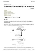
Four routers must be interconnected in a hub-and-spoke Frame Relay configuration. Router R1 is the hub, and
routers R2, R3, and R4 are spoke routers. The Frame Relay connections will be established using Frame Relay
point-to-point connections over subinterfaces from R1 to each spoke router. Routing will be established using
static routes on the hub router and default routes on all spoke routers. The frame relay switch(es) have already
been configured within the cloud.
Remote administrative access is established using SSH with the username admin and password cisco.
Task 1: Configure Frame Relay and Static Routing on the Hub Router (R1).
Step 1. Verify Default Configurations.
a. On all four routers, enter privileged EXEC mode with the password cisco.
b. From privileged EXEC mode on all four routers, issue the show running-config command to
verify running configurations.
Note: All routers have been preconfigured with hostnames, enable password, and SSH connectivity. All LAN
interfaces have also been configured with IP addresses and are currently active.
c. Use the show ip route command to verify routing tables.
Step 2. Configure the Physical Frame Relay Interface on R1.
When configuring frame-relay subinterfaces, the main physical interface must be enabled for Frame Relay
connectivity; therefore, configure Frame Relay on the serial 0/0/0 interface of router R1. The Frame Relay LMI
type is autosensed and will not be manually configured.
a. From privileged EXEC mode on R1, enter global configuration mode.
b. Enter the following commands on R1 to enable Frame Relay on the physical interface.
R1(config)# interface serial0/0/0
R1(config-if)# encapsulation frame-relay
R1(config-if)# no shutdown
Step 3. Configure the Subinterfaces on R1.
Frame Relay subinterfaces will be configured using point-to-point Frame Relay. Configure the point-to-point
connections to the three spoke routers via subinterfaces and assign the appropriate dlci number to each frame
relay connection, see the table below:
S0/0/0.102 IP: 10.0.1.1 DLCI: 102
All contents are Copyright © 1992–2008 Cisco Systems, Inc. All rights reserved. This document is Cisco Public Information. Page 1 of 5
CCNA Exploration
LAN Switching and Wireless
SM: 255.255.255.252
S0/0/0.103 IP: 10.0.1.5
SM: 255.255.255.252
DLCI: 103
S0/0/0.104 IP: 10.0.1.9
SM: 255.255.255.252
DLCI: 104
a. Create and configure subinterface s0/0/0.102. From global configuration mode, enter the following
commands:
R1(config)# interface Serial0/0/0.102 point-to-point
R1(config-subif)# ip address 10.0.1.1 255.255.255.252
R1(config-subif)# frame-relay interface-dlci 102
R1(config-subif)# exit
b. Repeat the above steps to create and configure subinterface s0/0/0.103 and s0/0/0.104.
R1(config)# interface Serial0/0/0.103 point-to-point
R1(config-subif)# ip address 10.0.1.5 255.255.255.252
R1(config-subif)# frame-relay interface-dlci 103
R1(config-subif)# exit
R1(config)# interface Serial0/0/0.104 point-to-point
R1(config-subif)# ip address 10.0.1.9 255.255.255.252
R1(config-subif)# frame-relay interface-dlci 104
R1(config-subif)# exit
Step 4. Configure Static Routing on R1 to reach the LANs of each spoke router.
Routing between sites could be configured using dynamic or static routing. In this activity, you will configure static
routes to each remote LAN sites.
a. From global configuration mode, enter the following static routes.
R1(config)# ip route 10.20.20.0 255.255.255.0 10.0.1.2
R1(config)# ip route 10.30.30.0 255.255.255.0 10.0.1.6
R1(config)# ip route 10.40.40.0 255.255.255.0 10.0.1.10
b. Exit out of configuration mode and issue the show running-config command to view the final
configuration on R1.
Task 2: Configure Frame Relay and Default routing on the Spoke Routers.
Step 1. Configure the Physical Frame Relay Interface on the spoke routers.
Just as we configured the hub router for Frame Relay, the spoke routers must also be configured.
a. From privileged EXEC mode on R2, enter global configuration mode.
b. Configure the main physical interface for Frame Relay connectivity. Enter the following commands on
R2.
R2(config)# interface serial0/0/0
R2(config-if)# encapsulation frame-relay
R2(config-if)# no shutdown
All contents are Copyright © 1992–2007 Cisco Systems, Inc. All rights reserved. This document is Cisco Public Information. Page 2 of 5
CCNA Exploration
LAN Switching and Wireless
Step 2. Configure the Subinterfaces on R2.
From global configuration mode, enter the following commands to create and configure the subinterface. Assign
DLCI number 101 to the connection.
R2(config)# interface Serial0/0/0.101 point-to-point
R2(config-subif)# ip address 10.0.1.2 255.255.255.252
R2(config-subif)# frame-relay interface-dlci 101
R2(config-subif)# exit
Step 3. Configure Default Routing on R2.
From global configuration mode, enter the following static routes.
R2(config)# ip route 0.0.0.0 0.0.0.0 10.0.1.1
Step 4. Repeat Steps 1 – 3 on R3 and R4.
a. On router R3, configure the following commands. Assign DLCI 101 to the frame relay connection
R3(config)# interface serial0/0/0
R3(config-if)# encapsulation frame-relay
R3(config-if)# no shutdown
R3(config)# interface Serial0/0/0.101 point-to-point
R3(config-subif)# ip address 10.0.1.6 255.255.255.252
R3(config-subif)# frame-relay interface-dlci 101
R3(config-subif)# exit
R3(config)# ip route 0.0.0.0 0.0.0.0 10.0.1.5
b. On router R4, configure the following commands. Assign DCLI 101 to the frame-relay connection.
R4(config)# interface serial0/0/0
R4(config-if)# encapsulation frame-relay
R4(config-if)# no shutdown
R4(config)# interface Serial0/0/0.101 point-to-point
R4(config-subif)# ip address 10.0.1.10 255.255.255.252
R4(config-subif)# frame-relay interface-dlci 101
R4(config-subif)# exit
R4(config)# ip route 0.0.0.0 0.0.0.0 10.0.1.9
Task 4: Verify Connectivity.
Step 1. Verify the Frame Relay network.
After configuring Frame Relay on all routers, verify the Frame Relay configuration on R1.
a. Issue the show frame-relay map command on R1 to verify the connections to the spoke routers.
R1# show frame-relay map
Serial0/0/0.102 (up): point-to-point dlci, dlci 102, broadcast, status defined,
active
Serial0/0/0.103 (up): point-to-point dlci, dlci 103, broadcast, status defined,
active
Serial0/0/0.104 (up): point-to-point dlci, dlci 104, broadcast, status defined,
active
b. Next, issue the show frame-relay lmi command on R1.
All contents are Copyright © 1992–2007 Cisco Systems, Inc. All rights reserved. This document is Cisco Public Information. Page 3 of 5
CCNA Exploration
LAN Switching and Wireless
R1# show frame-relay lmi
LMI Statistics for interface Serial0/0/0 (Frame Relay DTE) LMI TYPE = CISCO
Invalid Unnumbered info 0 Invalid Prot Disc 0
Invalid dummy Call Ref 0 Invalid Msg Type 0
Invalid Status Message 0 Invalid Lock Shift 0
Invalid Information ID 0 Invalid Report IE Len 0
Invalid Report Request 0 Invalid Keep IE Len 0
Num Status Enq. Sent 26 Num Status msgs Rcvd 26
Num Update Status Rcvd 0 Num Status Timeouts 16
LMI Statistics for interface Serial0/0/0.102 (Frame Relay DTE) LMI TYPE = CISCO
Invalid Unnumbered info 0 Invalid Prot Disc 0
Invalid dummy Call Ref 0 Invalid Msg Type 0
Invalid Status Message 0 Invalid Lock Shift 0
Invalid Information ID 0 Invalid Report IE Len 0
Invalid Report Request 0 Invalid Keep IE Len 0
Num Status Enq. Sent 0 Num Status msgs Rcvd 0
Num Update Status Rcvd 0 Num Status Timeouts 16
LMI Statistics for interface Serial0/0/0.103 (Frame Relay DTE) LMI TYPE = CISCO
Invalid Unnumbered info 0 Invalid Prot Disc 0
Invalid dummy Call Ref 0 Invalid Msg Type 0
Invalid Status Message 0 Invalid Lock Shift 0
Invalid Information ID 0 Invalid Report IE Len 0
Invalid Report Request 0 Invalid Keep IE Len 0
Num Status Enq. Sent 0 Num Status msgs Rcvd 0
Num Update Status Rcvd 0 Num Status Timeouts 16
LMI Statistics for interface Serial0/0/0.104 (Frame Relay DTE) LMI TYPE = CISCO
Invalid Unnumbered info 0 Invalid Prot Disc 0
Invalid dummy Call Ref 0 Invalid Msg Type 0
Invalid Status Message 0 Invalid Lock Shift 0
Invalid Information ID 0 Invalid Report IE Len 0
Invalid Report Request 0 Invalid Keep IE Len 0
Num Status Enq. Sent 0 Num Status msgs Rcvd 0
Num Update Status Rcvd 0 Num Status Timeouts 16
c. Finally, issue the show frame-relay pvc command on R1.
R1# show frame-relay pvc
PVC Statistics for interface Serial0/0/0 (Frame Relay DTE)
DLCI = 102, DLCI USAGE = LOCAL, PVC STATUS = ACTIVE, INTERFACE = Serial0/0/0.102
input pkts 14055 output pkts 32795 in bytes 1096228
out bytes 6216155 dropped pkts 0 in FECN pkts 0
in BECN pkts 0 out FECN pkts 0 out BECN pkts 0
in DE pkts 0 out DE pkts 0
out bcast pkts 32795 out bcast bytes 6216155
DLCI = 103, DLCI USAGE = LOCAL, PVC STATUS = ACTIVE, INTERFACE = Serial0/0/0.103
input pkts 14055 output pkts 32795 in bytes 1096228
out bytes 6216155 dropped pkts 0 in FECN pkts 0
in BECN pkts 0 out FECN pkts 0 out BECN pkts 0
in DE pkts 0 out DE pkts 0
out bcast pkts 32795 out bcast bytes 6216155
DLCI = 104, DLCI USAGE = LOCAL, PVC STATUS = ACTIVE, INTERFACE = Serial0/0/0.104
input pkts 14055 output pkts 32795 in bytes 1096228
out bytes 6216155 dropped pkts 0 in FECN pkts 0
All contents are Copyright © 1992–2007 Cisco Systems, Inc. All rights reserved. This document is Cisco Public Information. Page 4 of 5
CCNA Exploration
LAN Switching and Wireless
in BECN pkts 0 out FECN pkts 0 out BECN pkts 0
in DE pkts 0 out DE pkts 0
out bcast pkts 32795 out bcast bytes 6216155
NOTE: PC1 and PC3 should now be able to successfully ping each other and the web server. If not, make sure
that you entered all the commands exactly as specified in the previous steps.
Step 2. Verify connectivity to the spoke LANs.
From the R1 router, ping the LAN interfaces of routers R2, R3, and R4. You should be able to successfully ping.
Step 3. Check results.
Your completion percentage should be 100%. If not, click Check Results to see which required components are
not yet completed.
All contents are Copyright © 1992–2007 Cisco Systems, Inc. All rights reserved. This document is Cisco Public Information. Page 5 of 5