Air Sampling and Industrial Hygiene Engineering - Chapter 9 pps
Bạn đang xem bản rút gọn của tài liệu. Xem và tải ngay bản đầy đủ của tài liệu tại đây (94.09 KB, 12 trang )
CHAPTER9
Microcircuitry and Remote Monitoring
With the advent of microcircuitry, GIS locators, and the Internet, this chapter discusses the new
monitoring options available. These protocols are particularly important in monitoring remote sites
for remediation or process adequacy and safety (explosive limits and toxic chemical limit
determinations).
9.1CONTINUOUS IAQ MONITORING IN BUILDINGS
Continuous IAQ monitoring empowers IAQ professionals and facility managers to
find and resolve IAQ issues quickly, before they become problems or crises. Intermittent
continuous IAQ monitoring supplements the qualified professional with permanently
installed scientific sensors that measure, record, and archive the indoor air quality in a
building 24 h per day, 365 days per year.
One of the indicators of air quality is carbon dioxide levels within the total airstream.
Carbon dioxide is generated through respiratory exhalation and incomplete combustion of
fuels. Continuous monitoring systems often use infrared beams to detect carbon monoxide
fluctuations (see Figure 2.6 on page 13).
Continous IAQ monitoring:
• Creates an early warning system for targeting and correcting IAQ issues
• Shows precisely when complaints disappear while demonstrating when most
building occupants are comfortable
• Assures, through operational linkage, proper equipment operation and mainte-
nance, even on remote sites
• Provides building owners and operators with ongoing proof of acceptable indoor
air quality
• Yields a continuous historical record of contaminant levels
The early warning capability, when it is combined with multiple small unobtrusive
monitoring devices, makes monitoring in sensitive areas possible. Using remote sensors,
monitoring is possible within laboratories, hospitals, vehicle shops, paint booths, haz-
ardous waste storage bunkers, and vehicular housings. In the event that the sensors detect
a problem, IAQ professionals can be summoned to assess the immediate situation.
© 2001 CRC Press LLC
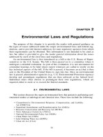
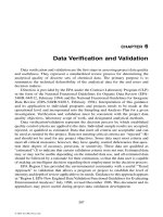
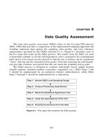
Figure 9.1 Fenceline monitoring equipment can be used for IAQ investigations, ambient air monitor-
ing, and hazardous waste site evaluation. This model can sample a maximum of 24
sequential sorbent tube samples in a single sampling sequence. Time, date, mass flow,
tube number, temperature, and wind direction and speed can be automatically logged into
memory and printed or downloaded into a personal computer. (BIOS International Corp.)
Sensors can be configured to assess multiple chemical exposure parameters. Changes
in the air quality pattern would initiate a warning signal in addition to regular information
transfer on-line. Further assessment with more sensitive devices may be the next require-
ment, or the response professional may simply document the event and issue an all-clear
decision. Engineering controls, as protection from chemical overexposure, may thus be
more efficient and more successful.
9.1.1IAQ Evaluations
Building air quality has emerged as a major issue involving the health and productiv-
ity of occupants. Building-related symptoms, often referred to as sick building syndrome,
have been traced to a variety of indoor air contaminants, with the underlying cause often
being deficiencies in ventilation.
Air handling, conditioning, and sequencing strategies designed for ventilation systems
and modification can be monitored using remote monitoring over telephone lines, dedi-
cated cable systems, fiber optic lines, and even the Internet. In some situations proper mon-
itoring can save energy while improving indoor air quality. An example might be the
redesign of outside air handling strategies to improve the performance of an economizer
cycle.
Despite the potential costs and liabilities of IAQ problems, they can often be remedied
by relatively simple changes in building operation. These studies can be completed
through both on-site and remote monitoring techniques.
Sorbent tube samplers are available to provide 24-h monitoring with a range of flow
rates and sorbent tube types (Figure 9.1).
9.1.1.1 Characterization for IAQ Assessment
IAQ is a developing area of knowledge. The following sequential approach is used
during an assessment:
• Definition with the client of the scope of work
• Serious questions of health, productivity, and credibility at stake when occupants
claim that a building is making them sick
© 2001 CRC Press LLC
• Discussion of various approaches to the investigation
• Problems often classified as either ventilation related or source related for pur-
poses of implementing sensible corrective measures
• Coordination of efforts among team members and current building occupants
• Oversight of monitoring and diagnostic activities
• Analysis of corrective actions
• Generation of performance specifications
IAQ investigations are conducted as follows:
• Describe how to form and test explanations for the problem and its solution. The
proposed approach to the building investigation may involve moving suspected
contaminant sources or manipulating HVAC controls to simulate conditions at
the time of complaints or to test possible corrective actions.
• IAQ measurement decision logic is developed.
• A decision to obtain IAQ-related measurements follows logically from other
investigative activities.
• Before starting to take measurements, investigators need a clear understanding
of how the results will be used. Without this understanding, it is impossible to
plan appropriate sampling locations and times, instrumentation, and analysis
procedures.
• Nonroutine measurements (such as relatively expensive sampling for VOCs are
not to be conducted without site-specific justification.
• Concentrations low enough to comply with industrial occupational standards could
still be harmful to children or other immune-compromised or sensitized occupants.
• Industrial IAQ problems tend to arise from high levels of individual chemical com-
pounds, so standards set limits for individual contaminants or contaminant classes.
• Exposure workplace standards are rarely exceeded in residences and schools.
Instead, IAQ investigators often find a large number of potential sources con-
tributing low levels of many contaminants to the air.
The following information is presented for each IAQ phased evaluation:
• The basic goals, methodology, and sequence of the investigation, the information
to be obtained, and the process of hypothesis development and testing, including
criteria for decision-making about further data-gathering
• Any elements of the work that will require a time commitment from staff or res-
idents, including information to be collected by the facility
• The schedule, cost, and work products, such as a written report, specifications,
and plans for mitigation work, supervision of mitigation work, and training pro-
grams for staff
• Additional tasks (and costs) that may be part of solving the IAQ problem, but
outside the scope of the contract (examples include medical examination of com-
plainants, laboratory fees, and contractor’s fees for mitigation work)
9.1.1.2 Source Assessment and Remediation
This IAQ phase includes either remote or on-site evaluation of known sources of air-
borne contaminants. When required, the IAQ team may also oversee necessary corrective
measures. Examples of such projects include modification of smoking areas, decontamina-
tion of microbial growth surfaces, and response to pesticide spills.
© 2001 CRC Press LLC
The most efficient way to protect building air quality is through programs that prevent
problems or address them in their earliest stages. In this regard IAQ aspects of facility design
and property audits may be most effective if initiated during design and initial occupancy.
Air quality precautions during facility design may include such steps as selecting and con-
ditioning of materials to limit off-gassing, evaluation of proposed ventilation schemes,
specifying remote sensing equipment, and preoccupancy testing of the building.
9.1.1.3 IAQ Risk Assessment
An investigation strategy based on evaluating building performance is used to solve a
problem without necessarily identifying a particular chemical compound as the cause. The
idea of testing the air to learn whether it is “safe’’ or “unsafe’’ is very appealing. However,
most existing standards for airborne pollutants were developed for industrial settings
where the majority of occupants are usually healthy adult men.
9.2 INDUSTRIAL/REMEDIATION PROCESS MONITORING
Through work efforts at industrial/remediation process sites, the basic precepts of
industrial hygiene monitoring should be implemented from initial design through ongo-
ing maintenance. The following is an example of an industrial hygiene scope of work to
provide answers in process safety management.
9.2.1 Process Safety Management Example Scope of Work
Process safety management (PSM) is a new strategy of management controls where
process limitations/hazards are identified and controlled so that injuries, spills, or hazards
are minimized. It is mandated in 29 CFR 1910.119 and applies to manufacturing plants and
other industries that are involved with large quantity chemical usage. The principal com-
ponents required for PSM compliance will benefit any industry trying to manage chemical
use. PSM is a complex system of controls, and in order to be successful in the implementa-
tion, upper management support and involvement is essential.
Standard operating procedures (SOPs) and O&M procedures must be reviewed. This
review will focus on processes that involve chemicals that are potential air contaminants or
other environmental media contaminants to the extent that health risk management is
required. The PSM standard mandates that the SOPs have provisions for every operating
phase, operating limitations, and safety and health considerations.
In general, the PSM requirements for
operating procedures include the following:
• Operating procedures that must address steps
for each operating phase, operating limits
between various operations, safety and health
considerations
• Copy of procedures that are readily accessible to
employees
• Implementation of safe work practices
© 2001 CRC Press LLC
A review of spill containment capabilities must also occur to identify current spill con-
tainment areas and any area limitations. Coordination of spill responses with regulatory
mandates and facility siting requirements should be addressed.
All hazard communication documentation must be reviewed. Hazard communication
is a set of procedures to communicate the hazards potentially associated with storage, han-
dling, shipping, or use of hazardous material. Communication is typically accomplished
through material safety data sheets (MSDS), shipping papers, emergency response proce-
dures, labels on containers, and training for employees. There must be open communica-
tion between all parties involved with hazardous material, including employer-employee,
employee-employer, shipper-receiver, and the business-community. Specific procedures
must be in place to facilitate this type of communication.
Past incidents will then be reviewed to determine any pattern or need for immediate
change. By looking at past events, safeguards can be identified to defray accidents and
releases in the future.
9.2.2 Provide List for Hazard and Operability Study
Current documents needed must be listed and acquired in order to complete a hazard
and operability study (HAZOP). The current piping and instrumentation diagrams (P&ID)
and other available design documents are a minimum requirement for review prior to ini-
tiation of the HAZOP.
Superfund Amendments and Reauthorization Act (SARA) Title III requires companies
that use a large amount of chemicals to provide information on their plants and to partici-
pate in community emergency response plans. The SARA Title III reporting will be
reviewed to identify any chemical uses that need to be addressed during the HAZOP study.
A process hazard analysis (PHA) provides employees and employers information to
assist them in making good decisions about safety. The PHA focuses on the causes or con-
tributing causes of potential accidents in the plant (fires, explosions, spills, releases, etc.).
The PHA is directed toward the equipment, human actions, control panels, etc. that may
cause failures in a system.
9.2.3 Process Hazard Analysis
Many variables must be considered when choosing the appropriate PHA technique to
use, including the size of the plant, the number of processes, the types of processes, and the
types of chemicals used. Many hazard analysis techniques can be used to determine the
appropriate process safety aspects and physical distribution of a plant or facility. The fol-
lowing techniques may be used in performing a PHA.
Hazard Analysis Techniques
• Checklist
• “What if’’
• HAZOP
• Failure mode and effect analysis
• Fault tree analysis
• Event tree analysis
• Distribution risk curves
© 2001 CRC Press LLC
9.2.3.1 Hazard and Operability Study
The HAZOP addresses each system and each element of a system that could deviate
from normal operations and, thus, cause a hazard. A full assessment of each process is
produced by looking at the hazards, consequences, causes, and personnel protection
needed.
9.2.3.2 Failure Modes and Effects Analysis (FMEA)
FMEA involves the systematic rating of each process and the hazards involved. It is
most effective when analyzing an individual process. It starts with a diagram of the design
of the processes and identifies all the possible components that could fail (i.e., valves,
hoses, pumps).
9.2.3.3 Fault Tree Analysis
Fault tree analysis is a graphical representation of all possible events of a hazard or haz-
ards that may occur if a fault/breach in a process occurs. This method centralizes on the
event that occurs, not so much the process. The graphical representation looks like a tree,
and a probability is applied by the reviewer to each fault on the tree.
9.2.4 Design Analysis
Increasingly, designs must take into consideration safety and health requirements.
These requirements include such topics as general safety, asbestos, lead, PCBs, volatile
chemical/painting/other airborne chemical hazards, and hazardous waste generation.
The following design documents should be prepared to provide the safety and health
design team information within engineering and construction documents.
9.2.4.1 Site Safety and Health Plans
For sites, including future building sites, requiring a phase I and/or phase II envi-
ronmental site assessment (ESA), a site safety and health plan must be developed for the
investigating team if hazardous wastes are still significantly present on-site. This plan
will
Components are analyzed for the following:
• Potential mode of failure
• Consequences of the failure
• Hazard class (high, moderate, low)
• Probability of failure
• Detection methods
• Compensating provisions/remarks
© 2001 CRC Press LLC
• Describe the minimum safety, health, and emergency response
• List anticipated major site tasks and operations
• Determine initial minimum levels of PPE
9.2.4.2 Health and Safety Design Analysis (HSDA)
During the design phase an HSDA is often developed. Site and/or hazard specific
safety and health considerations and protective measures are outlined in the HSDA. The
HSDA fully describes and justifies (using decision logic) the safety and health requirements
to be included in the contract specifications or work plans.
In the event that a site safety and health plan has been approved for prior on-site inves-
tigative work, and the same contractor will be conducting the construction work, the
HSDA only details the remaining construction work. If the remaining construction work
does not pose additional hazards in excess of those discussed in the prior site safety and
health plan, an HSDA will not be required.
9.2.4.3 Drawings
Drawings illustrate the following on an as-needed basis (i.e., either the drawings will
contain this information or will illustrate how the information will be presented during a
later design phase):
• The basic site layout, including the location of all existing utilities (e.g., water,
sewer, gas, electrical)
• All potential interferences with utility routings, including any existing infra-
structure that may pose an obstacle
• Site work zones for hazardous waste site work, including the EZ, the CRZ, and
the SZ (When a work activity will be duplicated at varying locations on-site, an
example of the placement of each zone is provided.)
• Schematic of decontamination facilities for both personnel and heavy equipment
(Ideally these facilities should be in separate locations.)
• Location of all emergency facilities: eyewash stations, drench showers, first aid
stations
• Routes to medical facilities
• Emergency and contingency plan staging areas
• Air-monitoring stations for background, area, and perimeter monitoring (If air
monitoring is not required for any of these areas, the drawing notes must contain
a negative declaration to this effect.)
• Waste collection, transfer, and disposal locations
9.2.4.4 Specifications
The contract requirements are fully developed from the HSDA and are described in a
specification section. All minimum site-specific, task-specific, and hazard-specific proce-
dures, precautions, and equipment determined necessary and described in the HSDA are
clearly biddable and enforceable contractual requirements within the specification sec-
tions.
For hazardous waste sites, the site description and contamination characterization por-
tion of the HSDA may be incorporated for information as a specification appendix.
© 2001 CRC Press LLC
In the event that a site safety and health plan has been approved for prior on-site inves-
tigative work, and the same contractor will be conducting the construction work:
• If the remaining remedial action construction work does not pose additional haz-
ards in excess of those discussed in the prior approved plan, a safety and health
specification section will not be required.
• If the remaining remedial action construction work does pose additional hazards
in excess of those discussed in the prior approved plan, but the additional haz-
ards can be adequately discussed in an addendum to the prior approved plan, a
safety and health specification section will not be required.
• In lieu of requiring that the contractor write a safety and health specification sec-
tion, a safety and health work plan may be required.
• If the remaining construction work does pose additional hazards in excess of
those discussed in the prior approved site safety and health plan, and the addi-
tional hazards cannot be adequately discussed in an addendum to the prior
approved site safety and health plan, a safety and health specification section will
be required.
During any design analysis the chemical use and potential contaminant issues must be
analyzed.
9.2.4.5 Design Analysis Example—Wastewater Treatment
The following is an example of the type of design analysis required to determine which
chemicals could become air contaminants during process operations. This example is an
excerpt from a design analysis that illustrates how process stream chemical activities are
analyzed.
Wastewater Treatment
• Each reaction tank has a propeller mixer.
• Detention time in each tank is from 15 to 45 min.
• Reaction times for different wastes, reducing agents, temperatures, pH, and
chromium concentrations.
After the Hexavalent Chromium Has Been Reduced to Trivalent Chromium
• The waste stream can be combined with other wastestreams containing common
metals. These combined waste streams can be treated by the hydroxide precipi-
tation process to remove chromium and the other common metals.
• Optimum levels for your metal waste treatment facilities may be slightly differ-
ent due to the “mix’’ of wastes being treated.
Cyanide Destruction by Oxidation
The cyanide ion (CN
Ϫ
) is extremely toxic and must be removed from metal wastes
before discharge to sewers or the environment. Cyanide toxicity (poisoning) in humans is
caused by an irreversible reaction with the iron in hemoglobin that results in loss of the
blood’s ability to transport oxygen.
© 2001 CRC Press LLC
If equipment failure occurs during the treatment of wastes containing cyanide,
extremely toxic gases could be released. Therefore all tanks or pits used for cyanide
destruction must be properly located and ventilated so that any gases produced will never
enter an area occupied by people.
Cyanide Sources and Treatment
Cyanide compounds are used
• In plating solutions for copper, zinc, cadmium, silver, and gold
• In the immersion stripping of various electrodeposits
• In some activating solutions
• Complexed with heavy metals such as zinc, cadmium, silver, gold, copper, nickel,
and iron
Flowing rinse waters after these production operations can become contaminated
with cyanide. Cyanide may be present as the simple alkali cyanides of sodium or
potassium.
For waste treatment control the two major groupings of cyanide compounds are seg-
regated into
• Those that can be oxidized by chlorination (also known as cyanides amenable to
chlorination)
• Those that resist oxidation by chlorination (also known as refracto-cyanides)
Both types are to toxic and must be removed or have their concentrations reduced below
toxic levels prior to discharge of the rinse waters.
Those compounds that are readily oxidized by chlorination are cyanides of
• Sodium
• Potassium
• Cadmium
• Zinc
The copper cyanide complex is also considered amenable to chlorination, although
longer reaction times are required (also for silver and gold cyanide complexes). The nickel
cyanide complex is more resistant to chlorination than the copper complex, yet it can
be considered as amenable to chlorination under extreme oxidizing conditions. Iron
complexes (most commonly the sodium ferrocyanide salt) are not readily oxidizable by
chlorine.
Pretreatment permits prescribe maximum limits for cyanides oxidizable by chlo-
rination and for total cyanide (the sum of those that can be chlorinated and those that
cannot).
• The average limits for amenable cyanides are 0.05 mg/l and for total cyanide
0.28 mg/l.
• The maximum concentrations for amenable and total cyanide are 0.65 mg/l and
1.2 mg/l.
© 2001 CRC Press LLC
Chemistry Involved
Waste treatment systems are designed to oxidize cyanide compounds with sodium
hypochlorite (NaClO). The hypochlorite is purchased at a 14 to 15% by weight concentra-
tion. This solution has been produced by the reaction between chlorine and sodium
hydroxide according to the reaction:
Cl
2
ϩ 2NaOH → NaClO ϩ NaCl ϩ H
2
O
Sodium cyanate (NaCNO) is formed by the reaction of hypochlorite and cyanide.
• This reaction is actually a simplification of the chlorination of cyanide; very rapid
intermediate reactions take place.
• Chlorine is freed from the hypochlorite by disassociation (a reversal of the for-
mation of hypochlorite shown above).
The chlorine actually reacts with the cyanide to form cyanogen chloride according to
NaCN ϩ Cl
2
→ CNCl ϩ NaCl
The cyanogen chloride then reacts with the sodium hydroxide to form the cyanate
according to
CNCl ϩ 2NaOH → NaCNO ϩ NaCl ϩ H
2
O
The cyanogen chloride is a gas that has limited solubility at neutral or low pH values.
At pH values of 10 or higher the reaction producing the cyanate is quite rapid for cyanides
that are not too tightly complexed with heavy metals. At lower pH values not only is the
reaction too slow, but also there is a good probability of liberating the cyanogen chloride
gas to the atmosphere. This gas is
• A lacrymator (produces tears)
• Readily apparent to those nearby
Oxidation of cyanate is possible by chlorination where the reaction is
2NaCNO ϩ 3NaOCl ϩ H
2
O → 2CO
2
ϩ N
2
ϩ 3NaCl ϩ 2NaOH
The carbon dioxide formed will react with alkali to produce carbonate. Any excess is
liberated into the atmosphere.
• The nitrogen has a limited solubility and also escapes into the air.
• This second stage oxidation reaction is faster at pH values slightly lower than the
initial reaction of cyanide to cyanate.
If the pH drops too low (below 7.0), then another reaction takes place with cyanate.
This reaction will hydrolyze with water to produce ammonia compounds.
© 2001 CRC Press LLC
From this discussion pH as a critical factor must be defined. The rate of reaction, as well
as the end products, depend upon maintaining proper pH values. The escape of cyanogen
chloride is inhibited by high pH values.
Another impact of the oxidizing potential of pH at 10.5 to 11.0 is the oxidizer millivolts
potential that results. Nitrogen chloride as an oxidizing gas essentially stops the reaction,
so higher potentials of 650 mV do not solve the problem.
Operators must realize the extreme hazards that can develop and produce toxic
cyanide gas whenever cyanide treatment processes are accidentally carried on at an
acidic pH.
• Where significant levels of cyanides exist, extremely hazardous conditions can
develop very quickly.
• Also when treating cyanides be sure to determine the pH at the start of the treat-
ment process. The adjustment of pH and the various set points for the treatment
system are to some extent dependent upon the concentration of cyanide and
cyanate, and the initial pH of the wastestreams.
• Adjusting the pH downward to 9.0 for a treatment process when the initial pH of
a cyanide solution is significantly higher could result in the evolution of toxic cya-
nide gas.
Cyanides complexed with zinc and cadmium react with the same rate as the simple
sodium and potassium cyanides. Because the various other metal complexes are more
resistant to oxidation by chlorination, long contact times are required.
In order to maintain a fast reaction rate, higher oxidizing potentials (additional excess
chlorine) are employed. This method is most important for the complexes of silver and
nickel.
When a cadmium cyanide complex is oxidized, the cadmium precipitates from solu-
tion as cadmium oxide. When oxidized, these metals precipitate from solution as hydrox-
ides of copper, nickel, and zinc.
However, the presence of silver cyanide presents an additional concern. The silver
cyanide complex when oxidized can precipitate as
• Silver chloride (a white precipitate)
• Silver oxide (a black precipitate)
Silver oxide is preferred; it is denser than silver chloride with the result that its removal
from the wastewater is easier. Higher oxidizing conditions favor the oxide formation;
lower oxidizing conditions favor the chloride formation.
The control devices are set to control the pH within the range of 10.5 to 11.5 for the
first-stage reaction (cyanide to cyanate) and the second-stage reaction (cyanate to
carbon dioxide and nitrogen). The control devices are set to maintain minimum oxidizing
potentials of
•
ϩ600 mV in the first stage and
• ϩ850 mV in the second stage
For the first stage reaction a minimum pH must be maintained. The top pH limit (11.5) is
established.
© 2001 CRC Press LLC
Excessive alkali (as measured by pH) results in suppression of oxidation-reduction
potential (ORP) values. The ORP value selected considers the need to have excess
hypochlorite present to dominate the reaction. Sodium hypochlorite always contains free
sodium hydroxide.
When the ORP controller requests the addition of hypochlorite, the pH can rise because
of this simultaneous addition of alkali. When the pH rises, the ORP value decreases, estab-
lishing an out-of-control condition. Adding more hypochlorite results in the instrumenta-
tion requesting still more hypochlorite even though there is no cyanide present. This
phenomenon is eliminated by the addition of acid whenever the pH rises too high.
© 2001 CRC Press LLC