Handbook of Small Electric Motors MAZ Part 10 docx
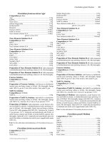
Bạn đang xem bản rút gọn của tài liệu. Xem và tải ngay bản đầy đủ của tài liệu tại đây (1.36 MB, 96 trang )
CHAPTER 4
DIRECT-CURRENT MOTORS
Chapter Contributors
Andrew E. Miller
Earl F. Richards
Alan W. Yeadon
William H. Yeadon
4.1
This chapter covers methods of calculating performance for direct-current (dc)
mechanically commutated motors. Section 4.1 discusses the electromagnetic circuit
for dc motors and series ac motors. Sections 4.2 and 4.3 establish some common
geometry and symbols and discuss commutation for dc motors. Section 4.4 presents
permanent-magnet direct-current (PMDC) calculation methods. Section 4.5 pre-
sents series dc and universal ac/dc performance calculations.Sections 4.6 and 4.7 dis-
cuss methods for calculating the performance of shunt- and compound-connected dc
motors. Finally, Secs. 4.8 and 4.9 discuss dc motor windings and automatic armature
winding.
4.1 THEORY OF DC MOTORS*
4.1.1 DC Series Motors
A series motor operating on direct current has characteristics similar to those when
it is operated on ac current at power-system frequencies. However, it is best to
describe dc and ac operation separately so that comparisons can be made.
The general equivalent electrical circuit of the series dc motor and its physical
construction is shown in Figs. 4.1 and 4.2.The motor consists of a stator having a con-
centrated field winding (Fig. 4.3) connected in series by way of a commutator to a
* Section contributed by Earl F. Richards.
wound armature (Fig. 4.4). One of the first things to be considered in the operation
of the motor are the motor and generator action, which exist simultaneously in the
armature circuit of the motor. These two principles are (1) the instantaneous elec-
tromotive force (emf), which is induced in the armature conductors when moving
with a velocity v within a magnetic field, and (2) the force produced on the conduc-
tors as the result of carrying an electric current in this same magnetic field.
4.2 CHAPTER FOUR
FIGURE 4.1 Series motor diagram: r
a
= armature resis-
tance measured at brushes, r
f
= main field resistance, and v =
applied voltage.
FIGURE 4.2 Series motor.
It is known that the instantaneous force on a conductor of length ᐉ carrying a cur-
rent i in a magnetic field B is:
f = Bi ᐉ sin θ N (4.1)
Or, in vector notation:
f = ᐉ (i × B) (4.2)
where θ is the angle between the direction of the magnetic field and the direction of
current flow in the conductor, B is in webers per square meter (teslas), i is in
DIRECT-CURRENT MOTORS 4.3
FIGURE 4.3 One pole of a series motor field winding.
FIGURE 4.4 Wound armature.
amperes, and ᐉ is in meters. Motors, by design, have the armature conductors and
magnetic flux at quadrature to one another.Therefore, the force becomes:
f = Biᐉ (4.3)
Assume a situation in Fig. 4.5 where a conductor of length ᐉ is located in a mag-
netic field and is free to move in the x direction perpendicular to the field. From the
preceding discussion, a force is produced on the conductor, causing it to move in the
x direction.Then:
V − ir = e or Vi − i
2
r = ei (4.4)
So, differential electrical energy into
the conductor less differential i
2
r loss
equals differential mechanical output
energy:
dW
elect
= dW
mech
(4.5)
ei dt = f dx where f = Biᐉ (4.6)
ei dt = Biᐉ dx (4.7)
e = Bᐉ = Bᐉv (4.8)
This force causes movement in the
conductor, which in turn causes a volt-
age to be induced into that conductor
which is opposite to the direction of the
original current. This is an important
concept in the operation of motors in
general and one which is used to discuss the operation of the series motor. This
induced voltage is usually called a counter-emf (cemf) voltage because of its opposi-
tion to the applied voltage.
This example also indicates that a reversible energy or power exchange is possi-
ble (i.e., between the mechanical and electrical systems). Therefore, the same
machine may operate as a motor or a generator, depending on the flow of energy in
the armature.
In the motor mode, the field and armature of a dc series motor are supplied with
the same current by an applied voltage, and a magnetic field (flux) is produced in the
magnetic circuit. Since the armature conductors (coils) are located in this field,each
of the conductors in the field experiences a force (torque) tending to make it move
(rotate), and as we have just indicated, a countervoltage (cemf) is produced oppos-
ing the applied voltage. Other than the cemf which the armature produces, we must
recognize that the armature circuit (coils) also produces a magnetic field of its own.
The armature, because of its commutator and brush construction, has a unidirec-
tional current and therefore produces a fixed-direction magnetomotive force (mmf),
measured in ampere-turns.This mmf is the product of the effective coil turns on the
armature and the current through those turns. It must be understood here that the
armature winding must be considered in developing those ampere-turns (i.e., there
may be parallel paths through the armature, with the possibility of the armature coils
being wound in series or parallel arrangements; hence, there will also be a division of
the total armature current in each of the windings).This topic is addressed later.The
following is a discussion of the action of the mmf produced by the armature.
dx
ᎏ
dt
4.4 CHAPTER FOUR
FIGURE 4.5 Conductor moving in a magnetic
field.
Armature Reaction. The conductors in the armature carry a current proportional
to the load. The magnetic field produced by this current reacts with the main field
produced by the same current flowing in the field coils. Figure 4.6 indicates two so-
called belts of armature conductors (coil sides) under each pole face. Each of the
conductors comprising these belts carries current in the same direction and hence
produces additive mmf. In addition, there are conductors which also carry unidirec-
tional currents but are not under the pole arcs. The important consideration here is
the effect of the presence of magnetic material in the pole pieces, armature core, and
armature teeth. The flux paths through the armature are influenced by the reluc-
tances of the paths. It is obvious that the reluctance of the flux paths under the pole
pieces is less than that of the paths adjacent to the brush area, which constitute a
material of much greater reluctance, namely air.
DIRECT-CURRENT MOTORS 4.5
FIGURE 4.6 Armature magnetic field.
Figure 4.6 indicates that the brushes are on the mechanical neutral axis (i.e.,
halfway between the poles).The general direction of the armature mmf is along the
brush axis at quadrature to the main field.The armature conductors adjacent to the
poles produce flux densities in the air gap which are equal and opposite at the pole
tips. Keep in mind that the flux density produced by the armature is directly related
to the armature current. (Also, a uniformly distributed flux density in the air gap is
attributed to the main field and is directly related to this same armature current.)
Now the net mmf (or flux in the air gap) is the result of both the main field mmf and
the armature field mmf. The resultant air gap flux is now increased at one pole tip
and reduced at the other pole tip because of the armature reaction. The flux distor-
tion in the air gap is illustrated in Fig. 4.7. In this figure, two poles and the armature
conductors beneath the poles have been unfolded to illustrate the distortion more
clearly. Ampere’s circuital law is useful here in determining the armature mmf. The
resulting air gap mmf is the result of the superposition of the field and armature
mmfs. MMF drops in the poles and armature iron are considered negligible com-
pared to the air gap mmf. For reference, positive direction for the mmfs is assumed
to be a flux out of a north pole. The armature mmf is shown as a linear relationship,
but actually, because the armature slots are discrete, this relationship is actually
made up of small discrete stair-step transitions. However, it is shown as a smooth
curve here for easier analysis.
It is obvious that the air gap flux varies along the pole face.Another observation
from the distortion mmf pattern is that harmonics are very present in the air gap
mmf. Also, because of symmetry, only odd harmonics can exist in an analysis of the
air gap mmf. It must also be remembered that in the case of a series ac motor, the
variation of flux distortion would be approximately the same, only pulsating.
The results of a Fourier analysis of the air gap flux harmonics for the case when
(N
f
I
f
)/(N
a
I
a
) = 7/5 are given in Figs. 4.8 to 4.10.The figures show the fundamental,the
fundamental plus third and fifth harmonics, and finally the fundamental and odd
harmonics, up to and including the fifteenth harmonic. The magnitudes of the odd
harmonics beginning with the fundamental are 8.94, 0.467, 1.41, 0.924, −0.028, −0.02,
0.523, and 0.0094.That is, the series can be represented as follows:
φ
air gap
= 8.94 cos θ+0.467 cos 3θ+1.41 cos 5θ+0.924 cos 7θ
− 0.028 cos 9θ−0.02 cos 11θ+0.523 cos 13θ+0.0094 cos 15θ+иии (4.9)
Of course, changing the pole arc or magnitudes of the armature and field mmfs
will change the harmonic content.The change in flux density across the air gap pro-
duces two effects: (1) a reduction in the total flux emanating from each pole,and (2)
4.6 CHAPTER FOUR
FIGURE 4.7 Flux distortion in the air gap.
a shift in the electrical neutral axis, lending to commutation problems due to the flux
distortion.
The flux distortion which the armature produces has been called a cross-
magnetizing armature reaction, and rightly so.The net effect is illustrated in Fig. 4.11,
showing the resultant field where the armature cross field is at right angles to the
main field. The result is a distortion of the net flux in the motor; the second effect,
which was indicated previously, is a reduction in the total main field flux.This reduc-
tion of flux is not too obvious; in fact, it would almost appear from Fig. 4.8 that the
vector addition of these two mmfs would lead to an increase in flux which would
occur with the brushes on the mechanical neutral axis.
DIRECT-CURRENT MOTORS 4.7
FIGURE 4.8 Fundamental frequency of air gap flux.
FIGURE 4.9 Air gap flux due to fundamental plus third and fifth harmonics.
This resulting decrease in flux can be attributed to magnetic saturation. Figure
4.12 illustrates how this comes about when one operates the motor at the knee of the
saturation curve. The area ABC is proportional to the reduction in flux at the pole
tip with a decrease in flux density, while the area CDE is proportional to the increase
in flux at the other pole tip. Note that the reduction in flux exceeds the increase in
4.8 CHAPTER FOUR
FIGURE 4.10 Air gap flux due to odd harmonics through fifteenth.
FIGURE 4.11 Field of armature with and without brush
shift.
flux because of the saturation effect. This is sometimes called the demagnetizing
effect of armature reaction. This demagnetization effect can be on the order of about
4 percent.
Both armature reaction distortion and flux can be reduced or eliminated by com-
pensation windings in the pole face or by increasing the reluctance at the pole tips;
the latter by either lamination design or a nonuniform air gap.
DIRECT-CURRENT MOTORS 4.9
FIGURE 4.12 Armature reaction resulting in main pole flux reduction.
Because the purpose of the commutator and brushes is to change the current in
a short-circuited coil from, say, a current of +I to −I in the length of time the coil is
short-circuited by the brushes,some arcing at the brushes is expected. One desires to
keep any voltage induced into the coil to a minimum in order to keep this arcing as
small as possible.
When the brushes are on the mechanical neutral position and the main field
becomes distorted, the coils being commutated will have an induced voltage from
the distorted air gap flux. A shifting of the brushes to a new neutral position is sug-
gested to keep the induced voltage to a minimum and keep the brush arcing low. It
should be recognized that the amount of distortion of the field is a function of the
ampere-turns of the armature and hence is dependent on the motor load. One then
realizes that the electrical neutral position is a function of the load and that shifting
brushes to an electrically neutral position is therefore not a matter of shifting them
to a unique point in space.
Brush shifting causes another effect—that is, a demagnetization effect on the air
gap flux. This effect is in addition to the demagnetizing effect which occurs because
of saturation. When the brushes are shifted, the pole axis of the armature is shifted.
The result is that the angle between the main field and the armature field is greater
than 90°.This process is also illustrated in Fig. 4.11.
In summary, there are two processes which cause reduction of the air gap flux:(1)
reduction due to cross-magnetization when the brushes are on the mechanical neu-
tral position, which changes the flux distribution across the pole face and the net flux
because of saturation effects, and (2) demagnetization resulting from a brush shift
and change of the armature pole orientation with respect to the main field, resulting
in the armature field mmf having a component in direct opposition to the main field
mmf.
Reactance Voltage and Commutation. It was indicated previously that during
commutation the current in the shorted coil(s) under a brush must reverse and
change direction. The self-inductance of the shorted winding by Lenz’s law induces
an emf in the shorted winding to oppose the change in coil current. This voltage is
sometimes called the reactance voltage. (Actually, it may be only a portion of the
reactance voltage, as is shown later.) This voltage slows down the reversal of current
and tends to produce sparks or arcing as the trailing commutator bar leaves a brush.
The reactance voltage hinders good commutation. The magnitude of this voltage
depends directly on the square of the number of coil turns, the current flowing, and
the armature velocity; it is inversely proportional to the reluctance of the magnetic
path.
When shifting brushes to seek an electrical neutral position on a motor, the shift-
ing is done in the opposite direction of armature rotation. It must be remembered
that the reactance voltage is an e = L(di/dt) voltage and is simply due to the current
change during commutation. It has nothing to do with induced voltage from air gap
flux. Shifting the brushes really does not help the reactance voltage. Theoretically,
there is no induced voltage on the neutral axis from the motor flux (in fact, dλ/dt
should be zero here since the coil sides are moving parallel to the flux). In order to
counteract the reactance voltage and induce a voltage opposite to the reactance
voltage, the brushes must be shifted further backward than the magnetic neutral
axis. At this point a dλ/dt voltage is induced into the commutated coil by the field
flux, which counteracts the reactance voltage.The result is that two voltages in oppo-
site polarities are induced into the shorted coil, thereby reducing brush arcing.
An important consideration is that there can be another component of the reac-
tance voltage which can occur when two coil sides are in the same slot and both are
undergoing commutation.There is then the following self-inductance term:
Reactance voltage = L
11
+ M
12
(4.10)
where the coil being considered is the coil carrying current i
1
and the coil in the same
slot undergoing commutation is carrying current i
2
. If there is more coupling
between coils, more mutual terms can exist.
Brushes are a very important consideration, and contrary to normal electrical
principles, one would assume that keeping the brush resistance low would assist in
reducing arcing at the brush commutator bar interface. This is far from the truth. In
fact, resistance commutation is now an accepted technology. Brushes normally have
a graphite or carbon formulation and hence introduce, by their characteristics, resis-
tance into the interface. If constant current density could be achieved at a brush for
all loads and speeds, an ideal condition would exist for commutation. Figure 4.13
illustrates what would occur if ideal conditions are assumed.The assumptions are as
follows:
di
2
ᎏ
dt
di
1
ᎏ
dt
4.10 CHAPTER FOUR
DIRECT-CURRENT MOTORS 4.11
FIGURE 4.13 Linear commutation.
●
The brush width is equal to that of a commutator segment.
●
The current density under a brush is constant.
●
The reactance voltage and resistance are zero.
●
The commutator bar insulation is small compared to the width of a commutator
segment.
Note that as the commutator passes beneath the brush, for the assumptions
given, the contact resistance is inversely proportional to the contact area. The
sequence in Fig. 4.13 illustrates how the current change occurs in an armature coil
under these ideal conditions. This change in surface contact changes the brush con-
tact resistance; hence, with constant current density, the change in current flow
changes linearly according to contact resistance. Remember, the resistance is
inversely proportional to the contact area.This ideal commutation has been termed
linear commutation because of the linear transfer of current in the commutated coil,
as indicated in Fig. 4.13.
If the brush width is greater than that of one commutator segment, linear com-
mutation still exists because the resistance still changes linearly; hence, the current
density remains constant. The commutation period is longer; hence, the rate of
change of current di/dt is reduced, and hence the reactance voltage is reduced also.
All of the assumptions made in the previous analysis cannot occur, and nonlinear
commutation results. The armature coils have resistance, have self- and mutual
inductance, and hence linear commutation cannot be attained.
If these nonlinearities do occur, then either undercommutation or overcommuta-
tion occurs. These are illustrated in Fig. 4.14. Since brush heating is a product of
brush resistance and the square of the current, linear commutation is preferred,as it
minimizes brush heating. That is, the squared value of the three forms of current
commutation in Fig. 4.13 is smallest for linear commutation.
4.12 CHAPTER FOUR
FIGURE 4.14 Overcommutation, undercommutation, and
linear commutation.
It is possible to develop a circuit model for the commutation process, as shown in
Fig. 4.15. The factors have previously been described, and they are restated here.
Consider the subject coil of turns N
1
, and self-inductance L
11
, and the current i
1
which is being commutated.
1. The voltage of self inductance (reactance voltage) of the commutated coil is
e
L1
= L
11
(4.11)
where i
1
is the current being commutated and L
11
is the self-inductance of the coil
being commutated.
di
1
ᎏ
dt
2. The voltage of mutual inductance of an adjacent coil in the same slot carrying
current i
2
and undergoing commutation and linked to the subject coil is
e
M1
= M
12
(4.12)
where M
12
is the mutual inductance between adjacent coils.
3. The voltage induced into the subject coil of turns N
1
when cutting flux φ
a
due to
the armature mmf is
e
a
= N
1
(4.13)
Sometimes this is called commutating voltage; it opposes the reactance voltage.This
can be controlled by brush overshifting to make e
a
cancel the voltages e
M1
and e
L1
.
dφ
a
ᎏ
dt
di
2
ᎏ
dt
DIRECT-CURRENT MOTORS 4.13
FIGURE 4.15 Commutation voltages.
4. There are voltage drops due to coil resistance r
c
; R
c
and R
c
, the left and right con-
tact resistances at the brush; and the brush resistance between commutator seg-
ments r
b
.
The commutation process is not simple, and brush composition and interface
film, measurements, and conditions all can be made to assist in the commutation
process. Maintaining a suitable interface film between the brush and the copper
commutator is extremely important. This interface is formed of copper oxide and
free particles of graphite film; it provides a general resistance commutation and sup-
plies lubricant to reduce surface friction and heat between the commutator and the
brush.
Torque-Speed Characteristics of DC Series Motors. The electrical equivalent
steady-state circuit is the most appropriate method for analyzing the motor. This
equivalent circuit is repeated in Fig. 4.16 for convenience.
4.14 CHAPTER FOUR
FIGURE 4.16 Electric circuit of series dc motor.
Writing Kirchhoff’s voltage law around the loop gives:
V = I
a
(r
f
+ r
a
) + E
cemf
(4.14)
= I
a
(r
f
+ r
a
) + E
g
(4.15)
The counter-emf E
g
was addressed earlier when discussing the voltage induced
into a conductor of length ᐉ and moving with a velocity v perpendicular to a mag-
netic field of flux density B. The counter-emf voltage E
g
was expressed as e and given
by:
e = Bᐉv (4.8)
It is necessary to modify this and express e in terms of the motor parameters.
Beginning with Faraday’s law:
E
g
= E
cemf
= N V (4.16)
where N is the number of conductors per armature path when Z is the total number
of conductors (coil sides) on the armature.
Then:
Z = number of slots × coils/slot × turns/coil × 2 (conductors/turn)
a = number of parallel paths through the armature
P = number of poles
n = armature speed, rpm
φ=flux per pole, maxwells
Then:
E
g
= E
cemf
=×10
−8
= K
e
φn V (4.17)
where φ is in lines (maxwells) and
K
e
=×10
−8
(4.18)
From the equivalent circuit, the developed power of the motor is E
g
I
a
; that is:
P
dev
= K
e
φnI
a
W (4.19)
P
dev
= hp (4.20)
T
dev
=
lbиft (4.21)
T
dev
= 7.04
φI
a
× 10
−8
lbиft (4.22)
T
dev
= 22.5
φI
a
× 10
−8
ozиin (4.23)
The equivalent circuit voltage equation then becomes
V = I
a
(r
f
+ r
a
) + K
e
φn (4.24)
And the motor speed equation becomes
n = (4.25)
For no load speed:
n
L
≈ (4.26)
V
ᎏ
K
e
φ
V − I
a
(r
f
+ r
a
)
ᎏᎏ
K
e
φ
ZP
ᎏ
a
ZP
ᎏ
60a
K
e
φnI
a
ᎏ
746
33,000
ᎏ
2πn
K
e
φnI
a
ᎏ
746
ZP
ᎏ
60a
ZφnP
ᎏ
60a
∆φ
ᎏ
∆t
DIRECT-CURRENT MOTORS 4.15
For stalled torque:
λ=K
e
φI
a,stalled
(4.27)
= K
e
φ (4.28)
Efficiency of DC Series Motors. Earlier discussion has indicated that a number of
losses occur in the series motor.These losses can be summarized as follows:
1. Copper loss in the armature winding I
2
a
r
a
2. Copper loss in the series field winding I
2
a
r
f
3. Brush contact loss
4. Friction (brush and bearing friction) and windage
5. Core loss (hysteresis and eddy current)
6. Stray load loss (losses in addition to those above)
A comment should be made on the brush contact loss, listed as number 3. Exper-
imentation and Institute of Electrical and Electronic Engineers (IEEE) specifica-
tions have suggested as an approximation that
Brush contact loss = brush voltage drop × armature brush current (4.29)
This expression was arrived at for carbon or graphite brushes by observing the brush
voltage drop as a function of current density. At high- and low-current steady-state
densities, the voltage falls off and approaches zero. However, in between these lim-
its the voltage drop is approximately constant at about 1 V per brush.Therefore, for
a pair of brushes this becomes 2 V. On small machines this voltage drop tends to
increase, since the tendency is for the voltage drop to increase for lower brush and
commutator temperatures.
Carbon and graphite materials have a resistivity many times that of copper and
have a negative temperature coefficient. This negative temperature coefficient is
attributed to the rise in brush voltage drop in small machines.
Stray load loss, as the term suggests, is a function of motor load and changes in
load. Changes in load produce changes in armature current and hence affect (1)
magnetic saturation in the magnetic circuit, (2) armature reaction changes, and (3)
eddy current loss changes.
Figure 4.17 presents a diagram displaying these losses. By definition:
Overall efficiency == (4.30)
= (4.31)
Sometimes both electrical and mechanical efficiencies are of interest in order to
determine where improvements can be made.
Mechanical efficiency = (4.32)
Electrical efficiency = (4.33)
electrical power output
ᎏᎏᎏᎏᎏ
electrical power output + electrical losses
useful mechanical output
ᎏᎏᎏᎏᎏ
mechanical output + rotational losses
useful mechanical output
ᎏᎏᎏ
total electrical input
output
ᎏᎏ
output + losses
output
ᎏ
input
V
ᎏ
r
a
4.16 CHAPTER FOUR
The conditions for maximum efficiency can be related to those losses which are con-
sidered to be constant and those that vary with the motor load current. If the losses
are segregated as follows:
K
1
= constant losses
K
2
= losses which vary linearly with I
a
K
3
= losses which vary as the square of I
a
Then the efficiency is
eff == (4.34)
= (4.35)
Equating this expansion to zero gives the condition for maximum efficiency.
VI
a
[V − K
2
− 2K
3
I
a
] − [VI
a
− (K
1
+ K
2
I
a
+ K
3
I
2
a
)]V = 0 (4.36)
−2K
3
I
2
a
+ K
1
+ K
3
I
2
a
= 0 (4.37)
K
3
I
2
a
= K
1
(4.38)
Thus, for maximum efficiency the constant losses must be equal to those that vary
as the square of the armature current. This is typical for all different pieces of rota-
tional electrical equipment.The constant losses usually are considered to be the core
losses, friction, and windage. Usually the brush loss is small.
4.1.2 AC Series Motors
One of the first considerations when considering ac operation of a series-wound
motor is: Does the motor develop a unidirectional torque when operated on ac sup-
VI
a
(V − K
2
− 2K
3
I
a
) −
[
VI
a
− (K
1
+ K
2
I
a
+ K
3
I
2
a
)
]
V
ᎏᎏᎏᎏᎏᎏ
(VI
a
)
2
deff
ᎏ
dI
a
VI
a
− (K
1
+ K
2
I
a
+ K
3
I
2
a
)
ᎏᎏᎏ
VI
a
input − losses
ᎏᎏ
input
DIRECT-CURRENT MOTORS 4.17
FIGURE 4.17 Losses in a series dc motor.
ply voltages? We know the answer is yes. Since the armature and field are connected
in series, a current reversal in the field also produces a current reversal in the arma-
ture. The torque is therefore in the same direction. As indicated previously, the con-
struction must be an ac type with a completely laminated magnetic path. If it were
not laminated it would react as a solid-core inductor, with extremely high eddy cur-
rent losses.
The basic phasor and electrical circuit diagram of a series ac motor is shown in
Fig. 4.18. The common current in both armature and field produce a motor flux
which is nearly in phase with the current, the small difference being the hysteresis
and eddy current effects, which are not accounted for in the phasor diagram. Seven
voltages are required to overcome the applied voltage. These are the voltages pro-
duced by the leakage reactances and resistances of both armature and field, the
transformer voltage E
Tf
, the commutator brush drop, and the counter-emf voltage
E
g
. When the armature is rotating, the armature conductors, which are moving
through an alternating field flux, generate an alternating voltage E
g
which is in phase
with the flux, as indicated on the diagram.
4.18 CHAPTER FOUR
FIGURE 4.18 Series ac motor: (a) equivalent circuit and (b) phasor dia-
gram.
(b)
(a)
This voltage is proportional to the magnitude of the flux and the rate at which it
is cutting the flux (Faraday’s law). Since the flux is a sinusoidally varying quantity,
the voltage will also vary sinusoidally at the same frequency as the flux wave. The
transformer voltage E
Tf
has been included and reflects the Faraday voltage induced
into the field by the core flux. A similar voltage would be present in the armature,
but it is small in comparison to E
Tf
and has not been included in the phasor diagram.
The phasor sum of these voltages then represents the applied voltage V and the
basic phasor diagram of the ac series motor. Here all voltages are root mean square
(RMS) quantities. As previously mentioned, the effects of hysteresis and eddy cur-
rents have not been taken into account, nor have the effects of commutation and
brush shifting.The power factor angle θ is also indicated on the diagram and repre-
sents the power factor at the input motor terminals.
Several things are apparent from the phasor diagram:
1. At starting, the generated voltage E
g
is zero. Hence, the starting current is lim-
ited only by the impedances of the armature and field and the transformer volt-
age E
Tf
.
2. The motor draws a lagging power factor cos θ.
3. As the motor speed increases at a constant line voltage, the motor current
decreases and the power factor improves, which is a good reason to run a motor
at high armature velocities.
4. A reduction in frequency also improves the power factor by reducing the reac-
tance drops in both armature and field.
At this point it should be obvious that dc and ac performance of series motors
must differ due to reactance and transformer voltages and also due to ac losses
(additional hysteresis and eddy current losses—that is, core losses—and possible
changes in ac resistance as compared to dc resistance of the armature and field).
Note that in the development of the phasor diagram leakage reactance voltages for
both the field and armature, as well as a transformer voltage in the main field, have
been included. It is appropriate to develop some mathematical formulations and
basis for these voltages. In reality, the leakage reactance and transformer voltage
result from an application of Faraday’s law and are broken down into two parts to
obtain each voltage. This Faraday voltage is expressed in instantaneous form and
consists of two parts, as follows.
e
f
= e
Tf
+ e
ᐉ
(4.39)
where e
f
= Faraday voltage
e
Tf
= transformer voltage
e
ᐉ
= leakage reactance voltage
Then:
e
f
= (λ
M
+λ
ᐉ
) = N
f
(φ
M
+φ
ᐉ
) (4.40)
where φ
M
is the flux within the complete magnetic motor circuit and φ
ᐉ
is the leakage
flux.
Then:
λ
f
= N
f
+
(4.41)
Ᏺ
ᎏ
ᐉ
Ᏺ
ᎏ
M
d
ᎏ
dt
d
ᎏ
dt
DIRECT-CURRENT MOTORS 4.19
where Ᏺ is the ampere-turns of the main field and
M
and
ᐉ
are the reluctances of
the motor magnetic circuit and the leakage path, respectively.
Then:
λ
f
= N
f
i + i
(4.42)
= i + i (4.43)
Then:
e
f
= и + и (4.44)
= L
f
+ L
ᐉ
(4.45)
where L
f
and L
ᐉ
are the inductances associated with the two fluxes present in the
main field winding.
Now, in the steady-state response E
f
can be written as follows:
E
f
= E
Tf
+ E
ᐉ
= jωL
f
I + jωL
ᐉ
I (4.46)
= jx
f
I + jx
ᐉ
I (4.47)
where jx
ᐉ
is the leakage reactance, and the voltage and current are expressed in RMS
values.
If we assume that the applied voltage is sinusoidal, the Faraday voltage also will
be sinusoidal, and it is possible to express the transformer voltage E
Tf
in terms of
other variables.
By Faraday’s law,
e
Tf
= N
f
(4.48)
φ
M
= ͵ e
Tf
dt (4.49)
if we represent
e
Tf
= ͙2
ෆ
E
Tf
sin (ωt +α) (4.50)
φ
M
= cos (ωt +α) +φ
c
(4.51)
where E
Tf
is the rms value.
The constant of integration φ
c
is a transient quantity and disappears in the steady
state analysis. Hence:
φ
M
= cos (ωt +α) (4.52)
φ
M,max
= (4.53)
͙2
ෆ
E
Tf
ᎏ
N
f
ω
͙2
ෆ
E
Tf
ᎏ
N
f
ω
͙2
ෆ
E
Tf
ᎏ
N
f
ω
1
ᎏ
N
f
dφ
M
ᎏ
dt
di
ᎏ
dt
di
ᎏ
dt
di
ᎏ
dt
N
f
2
ᎏ
ᐉ
di
ᎏ
dt
N
f
2
ᎏ
M
N
f
2
ᎏ
ᐉ
N
f
2
ᎏ
M
N
f
ᎏ
ᐉ
N
f
ᎏ
M
4.20 CHAPTER FOUR
Or
E
Tf
==4.44fN
f
φ
M,max
(4.54)
This is the general transformer voltage relationship common in transformer theory.
Development of the Equivalent Circuit for a Universal Motor Considering Brush
Shift. Begin by considering a two-energy-source system (i.e., a main field and an
armature) with no brushes (Fig. 4.19), where:
v
a
= voltage applied to armature
v
f
= voltage applied to field
r
a
= armature resistance
r
f
= field resistance
i
a
= armature current
i
f
= field current
With no brushes, we have the following:
v
a
= r
a
i
a
+ pλ
a
(4.55)
V
f
= r
f
i
f
+ pλ
f
(4.56)
2πfN
f
φ
M,max
ᎏᎏ
͙2
ෆ
DIRECT-CURRENT MOTORS 4.21
FIGURE 4.19 Consideration of universal motor brush shift.
where
p = d/dt (differential operator)
So, where
λ
a
= ᏸ
aa
i
a
+ ᏸ
af
i
f
(4.57)
λ
f
= ᏸ
fa
i
a
+ ᏸ
ff
i
f
(4.58)
all ᏸs could be functions of θ
r
.
Then:
v
a
= r
a
i
a
+ i
a
pᏸ
aa
+ ᏸ
aa
pi
a
+ i
f
pᏸ
af
+ ᏸ
af
pi
f
(4.59)
v
f
= r
f
i
f
+ i
a
pᏸ
fa
+ ᏸ
fa
pi
a
+ i
f
pᏸ
ff
+ ᏸ
ff
pi
f
(4.60)
Now:
λ
aa
= N
a
φ
a
= i
a
= ᏸ
aa
i
a
and λ
af
= i
f
= ᏸ
af
i
f
(4.61)
where
ᏸ
aa
= ᏸ
af
= (4.62)
With ᏸ
aa
and the plot of
aa
versus θ
r
(Fig. 4.20):
ᏸ
aa
=+cos (2θ
r
) (4.63)
See Figs. 4.21 and 4.22.
ᏸ
af
= ᏸ
fa
=−L cos (θ
r
) where L = (4.64)
The self-inductance of the field is a constant with
a round armature.
ᏸ
ff
= constant = L
ff
ᏸ
ff
= (4.65)
N
f
2
ᎏ
f
N
a
N
f
ᎏ
R
af
L
max
− L
min
ᎏᎏ
2
L
max
+ L
min
ᎏᎏ
2
N
a
N
f
ᎏ
af
N
2
a
ᎏ
aa
N
a
N
f
ᎏ
af
N
2
a
ᎏ
aa
4.22 CHAPTER FOUR
FIGURE 4.20 Plot of
aa
.
FIGURE 4.21 Mutual terms between arma-
ture and field.
FIGURE 4.22 Plot of ᏸ
af
.
Using the expressions for ᏸ
aa
, ᏸ
af
, ᏸ
fa
, and ᏸ
ff
gives the following:
v
a
= r
a
i
a
+ω
r
(L
min
− L
max
) sin (2θ
r
) +
΄
+ cos (2θ
r
)
΅
pi
a
+ω
r
L sin (θ
r
)i
f
− L cos (θ
r
)pi
f
(4.66)
And
v
f
= r
f
i
f
+ω
r
L sin (θ
r
)i
a
− L cos (θ
r
)pi
a
+ L
ff
pi
f
(4.67)
Now, add brushes at an angle θ
ra
. If the brushes were added with no shift, the
resulting magnetic field of the armature would be at quadrature to the f axis. This
would fix θ
r
at 90°. Since the brushes are shifted to θ
ra
, θ
r
is fixed at 90°+θ
ra
. Also,
shifting the brushes causes a voltage to be induced in the field winding from the
armature current, so ᏸ
fa
≠ 0. In fact, ᏸ
fa
= constant = L
fa
with θ
r
= 90°+θ
ra
. Then:
v
a
= r
a
i
a
−ω
r
(L
min
− L
max
) sin (2θ
ra
)i
a
+
΄
−
΅
cos (2θ
ra
)pi
a
+ω
r
L cos (θ
ra
)i
f
+ L sin (θ
ra
)pi
f
(4.68)
And
v
f
= r
f
i
f
+ L
fa
pi
a
+ L
ff
pi
f
(4.69)
Now, defining the constants:
L
af1
= L cos (θ
ra
) L
aa1
= (L
min
− L
max
) sin (2θ
ra
) (4.70)
L
af2
= L sin (θ
ra
) L
aa2
=
΄
− cos (2θ
ra
)
΅
(4.71)
The equations in matrix form now are as follows:
΄΅
=
΄΅΄΅
(4.72)
Or
v
f
= r
f
i
f
+ L
ff
pi
f
− L
fa
pi
a
(4.73)
v
a
=ω
r
L
af1
i
f
+ L
af2
pi
f
+ r
a
i
a
+ω
r
L
aa1
i
a
+ L
aa2
pi
a
(4.74)
From the preceding, the equivalent circuit can be drawn (Fig. 4.23). From this
equivalent circuit, the transient response of the series motor can be calculated.
4.1.3 Permanent-Magnet DC Motors (Shunt PM Field Motors)
The general equivalent electrical circuit of a PMDC motor and its physical con-
struction are shown in Figs. 4.24 and 4.25. The motor consists of a stator (Fig. 4.26)
having permanent magnets attached to a soft steel housing and a commutator con-
nected through brushes to a wound armature (Fig. 4.27). One of the first things to be
i
f
i
a
r
f
+ pL
ff
−pL
fa
ω
r
L
af1
+ pL
af2
r
a
+ω
r
L
aa1
+ pL
aa2
v
f
v
a
L
max
− L
min
ᎏᎏ
2
L
max
+ L
min
ᎏᎏ
2
L
max
− L
min
ᎏᎏ
2
L
max
+ L
min
ᎏᎏ
2
L
max
− L
min
ᎏᎏ
2
L
max
+ L
min
ᎏᎏ
2
DIRECT-CURRENT MOTORS 4.23
considered in the operation of the motor are the motor and generator action, which
exist simultaneously in the armature circuit of the motor. These two principles are
(1) the instantaneous emf, which is induced in the armature conductors when mov-
ing with velocity v within a magnetic field, and (2) the force produced on the con-
ductors as the result of carrying an electric current in this same magnetic field.
4.24 CHAPTER FOUR
FIGURE 4.23 Equivalent circuit of the series motor.
FIGURE 4.24 Permanent-magnet dc motor. r
a
= armature
resistance measured at brushes, e = motor counter-emf, and
v = applied voltage.
It is known that the instantaneous force on a conductor of length ᐉ carrying a cur-
rent i in a magnetic field B is:
f = Biᐉ sin θ N (4.1)
Or, in vector notation:
f = ᐉ(i × B) (4.2)
DIRECT-CURRENT MOTORS 4.25
FIGURE 4.25 Permanent-magnet dc motor.
FIGURE 4.26 Stator.