Harris'''' Shock and Vibration Handbook Part 2 doc
Bạn đang xem bản rút gọn của tài liệu. Xem và tải ngay bản đầy đủ của tài liệu tại đây (878.36 KB, 82 trang )
body while it is balanced, particularly
where the height of the body is great rel-
ative to a horizontal dimension. If a per-
fect point or edge support is used, the
equilibrium position is inherently unsta-
ble. It is only if the support has width that
some degree of stability can be achieved,
but then a resulting error in the location
of the line or plane containing the center-
of-gravity can be expected.
Another method of locating the
center-of-gravity is to place the body in a
stable position on three scales.From static
moments the vector weight of the body is
the resultant of the measured forces at the
scales, as shown in Fig. 3.2. The vertical
line through the center-of-gravity is
located by the distances a
0
and b
0
:
a
0
= a
1
(3.10)
b
0
= b
1
This method cannot be used with more than three scales.
MOMENT AND PRODUCT OF INERTIA
Computation of Moment and Product of Inertia.
2,3
The moments of inertia of
a rigid body with respect to the orthogonal axes X, Y, Z fixed in the body are
I
xx
= ͵
m
(Y
2
+ Z
2
) dm I
yy
= ͵
m
(X
2
+ Z
2
) dm I
zz
= ͵
m
(X
2
+ Y
2
) dm (3.11)
where dm is the infinitesimal element of mass located at the coordinate distances X,
Y, Z; and the integration is taken over the mass of the body. Similarly, the products
of inertia are
I
xy
= ͵
m
XY dm I
xz
= ͵
m
XZ dm I
yz
= ͵
m
YZ dm (3.12)
It is conventional in rigid body mechanics to take the center of coordinates at the
center-of-mass of the body. Unless otherwise specified, this location is assumed, and
the moments of inertia and products of inertia refer to axes through the center-of-
mass of the body. For a unique set of axes, the products of inertia vanish.These axes
are called the principal inertial axes of the body.The moments of inertia about these
axes are called the principal moments of inertia. The moments of inertia of a rigid
body can be defined in terms of radii of gyration as follows:
I
xx
= mρ
x
2
I
yy
= mρ
y
2
I
zz
= mρ
z
2
(3.13)
F
3
ᎏᎏ
F
1
+ F
2
+ F
3
F
2
ᎏᎏ
F
1
+ F
2
+ F
3
VIBRATION OF A RESILIENTLY SUPPORTED RIGID BODY 3.15
FIGURE 3.2 Three-scale method of locating
the center-of-gravity of a body. The vertical
forces F
1
, F
2
, F
3
at the scales result from the
weight of the body. The vertical line located by
the distances a
0
and b
0
[see Eqs. (3.10)] passes
through the center-of-gravity of the body.
8434_Harris_03_b.qxd 09/20/2001 11:32 AM Page 3.15
where I
xx
, are the moments of inertia of the body as defined by Eqs. (3.11), m is
the mass of the body, and ρ
x
, are the radii of gyration. The radius of gyration has
the dimension of length, and often leads to convenient expressions in dynamics of
rigid bodies when distances are normalized to an appropriate radius of gyration.
Solid bodies of various shapes have characteristic radii of gyration which sometimes
are useful intuitively in evaluating dynamic conditions.
Unless the body has a very simple shape, it is laborious to evaluate the integrals
of Eqs. (3.11) and (3.12). The problem is made easier by subdividing the body into
parts for which simplified calculations are possible. The moments and products of
inertia of the body are found by first determining the moments and products of iner-
tia for the individual parts with respect to appropriate reference axes chosen in the
parts, and then summing the contributions of the parts.This is done by selecting axes
through the centers-of-mass of the parts, and then determining the moments and
products of inertia of the parts relative to these axes. Then the moments and prod-
ucts of inertia are transferred to the axes chosen through the center-of-mass of the
whole body,and the transferred quantities summed. In general, the transfer involves
two sets of nonparallel coordinates
whose centers are displaced. Two trans-
formations are required as follows.
Transformation to Parallel Axes.
Referring to Fig. 3.3, suppose that X, Y,
Z is a convenient set of axes for the
moment of inertia of the whole body
with its origin at the center-of-mass. The
moments and products of inertia for a
part of the body are I
x″x″
,I
y″y″
,I
z″z″
,I
x″y″
,
I
x″z″
, and I
y″z″
, taken with respect to a set
of axes X″,Y″,Z″ fixed in the part and
having their center at the center-of-mass
of the part.The axes X′,Y′,Z′ are chosen
parallel to X″,Y″,Z″ with their origin at
the center-of-mass of the body. The per-
pendicular distance between the X″ and
X′ axes is a
x
; that between Y″ and Y′ is
a
y
; that between Z″ and Z′ is a
z
. The
moments and products of inertia of the
part of mass m
n
with respect to the X′,
Y′,Z′ axes are
I
x′x′
= I
x″x″
+ m
n
a
x
2
I
y′y′
= I
y″y″
+ m
n
a
y
2
(3.14)
I
z′z′
= I
z″z″
+ m
n
a
z
2
The corresponding products of inertia are
I
x′y′
= I
x″y″
+ m
n
a
x
a
y
I
x′z′
= I
x″z″
+ m
n
a
x
a
z
(3.15)
I
y′z′
= I
y″z″
+ m
n
a
y
a
z
If X″,Y″,Z″ are the principal axes of the part, the product of inertia terms on the
right-hand side of Eqs. (3.15) are zero.
3.16 CHAPTER THREE
FIGURE 3.3 Axes required for moment and
product of inertia transformations. Moments
and products of inertia with respect to the axes
X″,Y″,Z″ are transferred to the mutually paral-
lel axes X′,Y′,Z′ by Eqs. (3.14) and (3.15), and
then to the inclined axes X, Y, Z by Eqs. (3.16)
and (3.17).
8434_Harris_03_b.qxd 09/20/2001 11:32 AM Page 3.16
Transformation to Inclined Axes. The desired moments and products of iner-
tia with respect to axes X,Y, Z are now obtained by a transformation theorem relat-
ing the properties of bodies with respect to inclined sets of axes whose centers
coincide.This theorem makes use of the direction cosines λ for the respective sets of
axes. For example, λ
xx′
is the cosine of the angle between the X and X′ axes. The
expressions for the moments of inertia are
I
xx
=λ
xx′
2
I
x′x′
+λ
xy′
2
I
y′y′
+λ
xz′
2
I
z′z′
− 2λ
xx′
λ
xy′
I
x′y′
− 2λ
xx′
λ
xz′
I
x′z′
− 2λ
xy′
λ
xz′
I
y′z′
I
yy
=λ
yx′
2
I
x′x′
+λ
yy′
2
I
y′y′
+λ
yz′
2
I
z′z′
− 2λ
yx′
λ
yy′
I
x′y′
− 2λ
yx′
λ
yz′
I
x′z′
− 2λ
yy′
λ
yz′
I
y′z′
(3.16)
I
zz
=λ
zx′
2
I
x′x′
+λ
zy′
2
I
y′y′
+λ
zz′
2
I
z′z′
− 2λ
zx′
λ
zy′
I
x′y′
− 2λ
zx′
λ
zz′
I
x′z′
− 2λ
zy′
λ
zz′
I
y′z′
The corresponding products of inertia are
−I
xy
=λ
xx′
λ
yx′
I
x′x′
+λ
xy′
λ
yy′
I
y′y′
+λ
xz′
λ
yz′
I
z′z′
− (λ
xx′
λ
yy′
+λ
xy′
λ
yx′
)I
x′y′
− (λ
xy′
λ
yz′
+λ
xz′
λ
yy′
)I
y′z′
− (λ
xz′
λ
yx′
+λ
xx′
λ
yz′
)I
x′z′
−I
xz
=λ
xx′
λ
zx′
I
x′x′
+λ
xy′
λ
zy′
I
y′y′
+λ
xz′
λ
zz′
I
z′z′
− (λ
xx′
λ
zy′
+λ
xy′
λ
zx′
)I
x′y′
− (λ
xy′
λ
zz′
+λ
xz′
λ
zy′
)I
y′z′
− (λ
xx′
λ
zz′
+λ
xz′
λ
zx′
)I
x′z′
(3.17)
−I
yz
=λ
yx′
λ
zx′
I
x′x′
+λ
yy′
λ
zy′
I
y′y′
+λ
yz′
λ
zz′
I
z′z′
− (λ
yx′
λ
zy′
+λ
yy′
λ
zx′
)I
x′y′
− (λ
yy′
λ
zz′
+λ
yz′
λ
zy′
)I
y′z′
− (λ
yz′
λ
zx′
+λ
yx′
λ
zz′
)I
x′z′
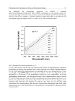
Experimental Determination of Moments of Inertia. The moment of inertia of
a body about a given axis may be found experimentally by suspending the body as a
pendulum so that rotational oscillations about that axis can occur.The period of free
oscillation is then measured, and is used with the geometry of the pendulum to cal-
culate the moment of inertia.
Two types of pendulums are useful:
the compound pendulum and the tor-
sional pendulum. When using the com-
pound pendulum, the body is supported
from two overhead points by wires,
illustrated in Fig. 3.4. The distance l is
measured between the axis of support
O–O and a parallel axis C–C through
the center-of-gravity of the body. The
moment of inertia about C–C is given by
I
cc
= ml
2
΄
2
− 1
΅
(3.18)
where τ
0
is the period of oscillation in sec-
onds, l is the pendulum length in inches,
g is the gravitational acceleration in
in./sec
2
, and m is the mass in lb-sec
2
/in.,
yielding a moment of inertia in lb-in sec
2
.
The accuracy of the above method
is dependent upon the accuracy with
which the distance l is known. Since the center-of-gravity often is an inaccessible
point, a direct measurement of l may not be practicable. However, a change in l can
be measured quite readily. If the experiment is repeated with a different support axis
O′–O′, the length l becomes l +∆l and the period of oscillation becomes τ
0
′.Then, the
distance l can be written in terms of ∆l and the two periods τ
0
, τ
0
′:
g
ᎏ
l
τ
0
ᎏ
2π
VIBRATION OF A RESILIENTLY SUPPORTED RIGID BODY 3.17
FIGURE 3.4 Compound pendulum method of
determining moment of inertia. The period of
oscillation of the test body about the horizontal
axis O–O and the perpendicular distance l
between the axis O–O and the parallel axis C–C
through the center-of-gravity of the test body
give I
cc
by Eq. (3.18).
8434_Harris_03_b.qxd 09/20/2001 11:32 AM Page 3.17
l =∆l
΄΅
(3.19)
This value of l can be substituted into Eq. (3.18) to compute I
cc
.
Note that accuracy is not achieved if l is much larger than the radius of gyration
ρ
c
of the body about the axis C–C (I
cc
= mρ
c
2
). If l is large, then (τ
0
/2π)
2
Ӎ l/g and the
expression in brackets in Eq. (3.18) is very small; thus, it is sensitive to small errors in
the measurement of both τ
0
and l. Consequently, it is highly desirable that the dis-
tance l be chosen as small as convenient, preferably with the axis O–O passing
through the body.
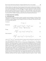
A torsional pendulum may be constructed with the test body suspended by a sin-
gle torsional spring (in practice, a rod or wire) of known stiffness, or by three flexi-
ble wires. A solid body supported by a single torsional spring is shown in Fig. 3.5.
From the known torsional stiffness k
t
and the measured period of torsional oscilla-
tion τ, the moment of inertia of the body about the vertical torsional axis is
I
cc
= (3.20)
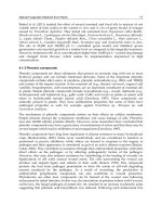
A platform may be constructed below the torsional spring to carry the bodies to
be measured, as shown in Fig. 3.6. By repeating the experiment with two different
bodies placed on the platform, it becomes unnecessary to measure the torsional stiff-
ness k
t
. If a body with a known moment of inertia I
1
is placed on the platform and an
oscillation period τ
1
results, the moment of inertia I
2
of a body which produces a
period τ
2
is given by
I
2
= I
1
΄΅
(3.21)
where τ
0
is the period of the pendulum composed of platform alone.
A body suspended by three flexible wires, called a trifilar pendulum, as shown in
Fig. 3.7, offers some utilitarian advantages. Designating the perpendicular distances
(τ
2
/τ
0
)
2
− 1
ᎏᎏ
(τ
1
/τ
0
)
2
− 1
k
t
τ
2
ᎏ
4π
2
(τ
0
′
2
/4π
2
)(g/∆l) − 1
ᎏᎏᎏ
[(τ
0
2
−τ
0
′
2
)/4π
2
][g/∆l] − 1
3.18 CHAPTER THREE
FIGURE 3.5 Torsional pendulum method of
determining moment of inertia. The period of
torsional oscillation of the test body about the
vertical axis C–C passing through the center-of-
gravity and the torsional spring constant k
t
give
I
cc
by Eq. (3.20).
FIGURE 3.6 A variation of the torsional pen-
dulum method shown in Fig. 3.5 wherein a light
platform is used to carry the test body. The
moment of inertia I
cc
is given by Eq. (3.20).
8434_Harris_03_b.qxd 09/20/2001 11:32 AM Page 3.18
of the wires to the vertical axis C–C through the center-of-gravity of the body by R
1
,
R
2
, R
3
, the angles between wires by φ
1
, φ
2
, φ
3
, and the length of each wire by l, the
moment of inertia about axis C–C is
I
cc
= (3.22)
Apparatus that is more convenient for
repeated use embodies a light platform
supported by three equally spaced wires.
The body whose moment of inertia is to
be measured is placed on the platform
with its center-of-gravity equidistant
from the wires.Thus R
1
= R
2
= R
3
= R and
φ
1
=φ
2
=φ
3
= 120°. Substituting these
relations in Eq. (3.22), the moment of
inertia about the vertical axis C–C is
I
cc
= (3.23)
where the mass m is the sum of the
masses of the test body and the plat-
form. The moment of inertia of the plat-
form is subtracted from the test result to
obtain the moment of inertia of the
body being measured. It becomes un-
necessary to know the distances R and l
in Eq. (3.23) if the period of oscillation is
measured with the platform empty, with
the body being measured on the platform, and with a second body of known mass m
1
and known moment of inertia I
1
on the platform. Then the desired moment of iner-
tia I
2
is
I
2
= I
1
΄΅
(3.24)
where m
0
is the mass of the unloaded platform, m
2
is the mass of the body being
measured, τ
0
is the period of oscillation with the platform unloaded, τ
1
is the period
when loaded with known body of mass m
1
, and τ
2
is the period when loaded with the
unknown body of mass m
2
.
Experimental Determination of Product of Inertia. The experimental determi-
nation of a product of inertia usually requires the measurement of moments of iner-
tia. (An exception is the balancing machine technique described later.) If possible,
symmetry of the body is used to locate directions of principal inertial axes, thereby
simplifying the relationship between the moments of inertia as known and the prod-
ucts of inertia to be found. Several alternative procedures are described below,
depending on the number of principal inertia axes whose directions are known.
Knowledge of two principal axes implies a knowledge of all three since they are
mutually perpendicular.
If the directions of all three principal axes (X′,Y′,Z′ ) are known and it is desir-
able to use another set of axes (X, Y, Z), Eqs. (3.16) and (3.17) may be simplified
[1 + (m
2
/m
0
)][τ
2
/τ
0
]
2
− 1
ᎏᎏᎏ
[1 + (m
1
/m
0
)][τ
1
/τ
0
]
2
− 1
mgR
2
τ
2
ᎏ
4π
2
l
R
1
sin φ
1
+ R
2
sin φ
2
+ R
3
sin φ
3
ᎏᎏᎏᎏᎏ
R
2
R
3
sin φ
1
+ R
1
R
3
sin φ
2
+ R
1
R
2
sin φ
3
mgR
1
R
2
R
3
τ
2
ᎏᎏ
4π
2
l
VIBRATION OF A RESILIENTLY SUPPORTED RIGID BODY 3.19
FIGURE 3.7 Trifilar pendulum method of
determining moment of inertia. The period of
torsional oscillation of the test body about the
vertical axis C–C passing through the center-of-
gravity and the geometry of the pendulum give
I
cc
by Eq. (3.22); with a simpler geometry, I
cc
is
given by Eq. (3.23).
8434_Harris_03_b.qxd 09/20/2001 11:32 AM Page 3.19
because the products of inertia with respect to the principal directions are zero. First,
the three principal moments of inertia (I
x′x′
,I
y′y′
,I
z′z′
) are measured by one of the
above techniques; then the moments of inertia with respect to the X,Y, Z axes are
I
xx
=λ
xx′
2
I
x′x′
+λ
xy′
2
I
y′y′
+λ
xz′
2
I
z′z′
I
yy
=λ
yx′
2
I
x′x′
+λ
yy′
2
I
y′y′
+λ
yz′
2
I
z′z′
(3.25)
I
zz
=λ
zx′
2
I
x′x′
+λ
zy′
2
I
y′y′
+λ
zz′
2
I
z′z′
The products of inertia with respect to the X, Y, Z axes are
−I
xy
=λ
xx′
λ
yx′
I
x′x′
+λ
xy′
λ
yy′
I
y′y′
+λ
xz′
λ
yz′
I
z′z′
−I
xz
=λ
xx′
λ
zx′
I
x′x′
+λ
xy′
λ
zy′
I
y′y′
+λ
xz′
λ
zz′
I
z′z′
(3.26)
−I
yz
=λ
yx′
λ
zx′
I
x′x′
+λ
yy′
λ
zy′
I
y′y′
+λ
yz′
λ
zz′
I
z′z′
The direction of one principal axis Z may be known from symmetry. The axis
through the center-of-gravity perpendicular to the plane of symmetry is a principal
axis.The product of inertia with respect to X and Y axes, located in the plane of sym-
metry, is determined by first establishing another axis X′ at a counterclockwise angle
θ from X, as shown in Fig. 3.8. If the three moments of inertia I
xx
,I
x′x′
, and I
yy
are
measured by any applicable means, the product of inertia I
xy
is
I
xy
= (3.27)
where 0 <θ<π. For optimum accuracy, θ
should be approximately π/4 or 3π/4.
Since the third axis Z is a principal axis,
I
xz
and I
yz
are zero.
Another method is illustrated in Fig.
3.9.
4, 5
The plane of the X and Z axes is a
plane of symmetry, or the Y axis is other-
wise known to be a principal axis of iner-
tia. For determining I
xz
, the body is
suspended by a cable so that the Y axis is
horizontal and the Z axis is vertical.Tor-
sional stiffness about the Z axis is pro-
vided by four springs acting in the Y
direction at the points shown. The body
is oscillated about the Z axis with vari-
ous positions of the springs so that the angle θ can be varied. The spring stiffnesses
and locations must be such that there is no net force in the Y direction due to a rota-
tion about the Z axis. In general, there is coupling between rotations about the X
and Z axes, with the result that oscillations about both axes occur as a result of an
initial rotational displacement about the Z axis. At some particular value of θ=θ
0
,
the two rotations are uncoupled; i.e., oscillation about the Z axis does not cause
oscillation about the X axis.Then
I
xz
= I
zz
tan θ
0
(3.28)
The moment of inertia I
zz
can be determined by one of the methods described under
Experimental Determination of Moments of Inertia.
I
xx
cos
2
θ+I
yy
sin
2
θ−I
x′x′
ᎏᎏᎏ
sin 2θ
3.20 CHAPTER THREE
FIGURE 3.8 Axes required for determining
the product of inertia with respect to the axes X
and Y when Z is a principal axis of inertia. The
moments of inertia about the axes X, Y, and X′,
where X′ is in the plane of X and Y at a counter-
clockwise angle θ from X, give I
xy
by Eq. (3.27).
8434_Harris_03_b.qxd 09/20/2001 11:32 AM Page 3.20
When the moments and product of inertia with respect to a pair of axes X and Z
in a principal plane of inertia XZ are known, the orientation of a principal axis P is
given by
θ
p
=
1
⁄2 tan
−1
(3.29)
where θ
p
is the counterclockwise angle from the X axis to the P axis. The second
principal axis in this plane is at θ
p
+ 90°.
Consider the determination of products of inertia when the directions of all
principal axes of inertia are unknown. In one method, the moments of inertia about
two independent sets of three mutually perpendicular axes are measured, and the
direction cosines between these sets of axes are known from the positions of the
axes. The values for the six moments of inertia and the nine direction cosines are
then substituted into Eqs. (3.16) and (3.17).The result is six linear equations in the
six unknown products of inertia, from which the values of the desired products of
inertia may be found by simultaneous solution of the equations. This method leads
to experimental errors of relatively large magnitude because each product of iner-
tia is, in general, a function of all six moments of inertia, each of which contains an
experimental error.
An alternative method is based upon the knowledge that one of the principal
moments of inertia of a body is the largest and another is the smallest that can be
obtained for any axis through the center-of-gravity. A trial-and-error procedure can
be used to locate the orientation of the axis through the center-of-gravity having the
maximum and/or minimum moment of inertia. After one or both are located, the
moments and products of inertia for any set of axes are found by the techniques pre-
viously discussed.
The products of inertia of a body also may be determined by rotating the body at
a constant angular velocity Ω about an axis passing through the center-of-gravity, as
illustrated in Fig. 3.10. This method is similar to the balancing machine technique
used to balance a body dynamically (see Chap. 39). If the bearings are a distance l
apart and the dynamic reactions F
x
and F
y
are measured, the products of inertia are
2I
xz
ᎏ
I
zz
− I
xx
VIBRATION OF A RESILIENTLY SUPPORTED RIGID BODY 3.21
FIGURE 3.9 Method of determining the product of inertia with
respect to the axes X and Z when Y is a principal axis of inertia.The
test body is oscillated about the vertical Z axis with torsional stiff-
ness provided by the four springs acting in the Y direction at the
points shown.There should be no net force on the test body in the Y
direction due to a rotation about the Z axis. The angle θ is varied
until, at some value of θ=θ
0
, oscillations about X and Z are uncou-
pled.The angle θ
0
and the moment of inertia about the Z axis give I
xz
by Eq. (3.28).
8434_Harris_03_b.qxd 09/20/2001 11:32 AM Page 3.21
I
xz
=− I
yz
=− (3.30)
Limitations to this method are (1) the size of the body that can be accommodated
by the balancing machine and (2) the angular velocity that the body can withstand
without damage from centrifugal forces. If the angle between the Z axis and a prin-
cipal axis of inertia is small, high rotational speeds may be necessary to measure the
reaction forces accurately.
PROPERTIES OF RESILIENT SUPPORTS
A resilient support is considered to be a
three-dimensional element having two
terminals or end connections. When the
end connections are moved one relative
to the other in any direction, the ele-
ment resists such motion. In this chap-
ter, the element is considered to be
massless; the force that resists relative
motion across the element is considered
to consist of a spring force that is
directly proportional to the relative dis-
placement (deflection across the ele-
ment) and a damping force that is
directly proportional to the relative
velocity (velocity across the element).
Such an element is defined as a linear
resilient support. Nonlinear elements are
discussed in Chap. 4; elements with mass
are discussed in Chap. 30; and nonlinear
damping is discussed in Chaps. 2 and 30.
In a single degree-of-freedom system or in a system having constraints on the
paths of motion of elements of the system (Chap. 2), the resilient element is con-
strained to deflect in a given direction and the properties of the element are defined
with respect to the force opposing motion in this direction. In the absence of such
constraints, the application of a force to a resilient element generally causes a
motion in a different direction. The principal elastic axes of a resilient element are
those axes for which the element, when unconstrained, experiences a deflection co-
lineal with the direction of the applied force. Any axis of symmetry is a principal
elastic axis.
In rigid body dynamics, the rigid body sometimes vibrates in modes that are cou-
pled by the properties of the resilient elements as well as by their location. For
example, if the body experiences a static displacement x in the direction of the X
axis only, a resilient element opposes this motion by exerting a force k
xx
x on the
body in the direction of the X axis, where one subscript on the spring constant k
indicates the direction of the force exerted by the element and the other subscript
indicates the direction of the deflection. If the X direction is not a principal elastic
direction of the element and the body experiences a static displacement x in the X
direction, the body is acted upon by a force k
yx
x in the Y direction if no displacement
y is permitted. The stiffnesses have reciprocal properties; i.e., k
xy
= k
yx
. In general,
F
y
l
ᎏ
Ω
2
F
x
l
ᎏ
Ω
2
3.22 CHAPTER THREE
FIGURE 3.10 Balancing machine technique
for determining products of inertia. The test
body is rotated about the Z axis with angular
velocity Ω. The dynamic reactions F
x
and F
y
measured at the bearings, which are a distance l
apart, give I
xz
and I
yz
by Eq. (3.30).
8434_Harris_03_b.qxd 09/20/2001 11:32 AM Page 3.22
the stiffnesses in the directions of the coordinate axes can be expressed in terms of
(1) principal stiffnesses and (2) the angles between the coordinate axes and the
principal elastic axes of the element. (See Chap. 30 for a detailed discussion of a
biaxial stiffness element.) Therefore, the stiffness of a resilient element can be rep-
resented pictorially by the combination of three mutually perpendicular, idealized
springs oriented along the principal elastic directions of the resilient element. Each
spring has a stiffness equal to the principal stiffness represented.
A resilient element is assumed to have damping properties such that each spring
representing a value of principal stiffness is paralleled by an idealized viscous
damper, each damper representing a value of principal damping. Hence, coupling
through damping exists in a manner similar to coupling through stiffness. Conse-
quently, the viscous damping coefficient c is analogous to the spring coefficient k;
i.e., the force exerted by the damping of the resilient element in response to a veloc-
ity ˙x is c
xx
˙x in the direction of the X axis and c
yx
˙x in the direction of the Y axis if ˙y is
zero. Reciprocity exists; i.e., c
xy
= c
yx
.
The point of intersection of the principal elastic axes of a resilient element is des-
ignated as the elastic center of the resilient element. The elastic center is important
since it defines the theoretical point location of the resilient element for use in the
equations of motion of a resiliently supported rigid body. For example, the torque on
the rigid body about the Y axis due to a force k
xx
x transmitted by a resilient element
in the X direction is k
xx
a
z
x, where a
z
is the Z coordinate of the elastic center of the
resilient element.
In general, it is assumed that a resilient element is attached to the rigid body by
means of “ball joints”; i.e., the resilient element is incapable of applying a couple to
the body. If this assumption is not made, a resilient element would be represented
not only by translational springs and dampers along the principal elastic axes but
also by torsional springs and dampers resisting rotation about the principal elastic
directions.
Figure 3.11 shows that the torsional elements usually can be neglected. The
torque which acts on the rigid body due to a rotation β of the body and a rotation b
of the support is (k
t
+ a
z
2
k
x
) (β−b), where k
t
is the torsional spring constant in the β
direction. The torsional stiffness k
t
usually is much smaller than a
z
2
k
x
and can be ne-
glected.Treatment of the general case indicates that if the torsional stiffnesses of the
resilient element are small compared with the product of the translational stiffnesses
times the square of distances from the elastic center of the resilient element to the
center-of-gravity of the rigid body, the torsional stiffnesses have a negligible effect
on the vibrational behavior of the body. The treatment of torsional dampers is com-
pletely analogous.
EQUATIONS OF MOTION FOR A RESILIENTLY
SUPPORTED RIGID BODY
The differential equations of motion for the rigid body are given by Eqs. (3.2) and
(3.3), where the F’s and M’s represent the forces and moments acting on the body,
either directly or through the resilient supporting elements. Figure 3.12 shows a view
of a rigid body at rest with an inertial set of axes
ළ
X,
ළ
Y,
ළ
Z and a coincident set of axes
X,Y, Z fixed in the rigid body, both sets of axes passing through the center-of-mass.A
typical resilient element (2) is represented by parallel spring and viscous damper
combinations arranged respectively parallel with the
ළ
X,
ළ
Y,
ළ
Z axes. Another resilient
element (1) is shown with its principal axes not parallel with
ළ
X,
ළ
Y,
ළ
Z.
VIBRATION OF A RESILIENTLY SUPPORTED RIGID BODY 3.23
8434_Harris_03_b.qxd 09/20/2001 11:32 AM Page 3.23
The displacement of the center-of-
gravity of the body in the
ළ
X,
ළ
Y,
ළ
Z direc-
tions is in Fig. 3.1 indicated by x
c
,y
c
,z
c
,
respectively; and rotation of the rigid
body about these axes is indicated by a,
b, g, respectively. In Fig. 3.12, each
resilient element is represented by three
mutually perpendicular spring-damper
combinations. One end of each such
combination is attached to the rigid
body; the other end is considered to
be attached to a foundation whose cor-
responding translational displacement is
defined by u, v, w in the
ළ
X,
ළ
Y,
ළ
Z di-
rections, respectively, and whose rota-
tional displacement about these axes is
defined by a, b, g, respectively. The point
of attachment of each of the idealized
resilient elements is located at the coor-
dinate distances a
x
,a
y
,a
z
of the elastic
center of the resilient element.
Consider the rigid body to experi-
ence a translational displacement x
c
of
its center-of-gravity and no other dis-
placement, and neglect the effects of the
viscous dampers.The force developed by a resilient element has the effect of a force
−k
xx
(x
c
− u) in the X direction, a moment k
xx
(x
c
− u)a
y
in the γ coordinate (about the
Z axis), and a moment −k
xx
(x
c
− u)a
z
in the β coordinate (about the Y axis). Further-
more, the coupling stiffness causes a force −k
xy
(x
c
− u) in the Y direction and a force
−k
xz
(x
c
− u) in the Z direction. These forces have the moments k
xy
(x
c
− u)a
z
in the α
coordinate; −k
xy
(x
c
− u)a
x
in the γ coordinate; k
xz
(x
c
− u)a
x
in the β coordinate; and
−k
xz
(x
c
− u)a
y
in the α coordinate. By considering in a similar manner the forces and
moments developed by a resilient element for successive displacements of the rigid
body in the three translational and three rotational coordinates, and summing over
the number of resilient elements, the equations of motion are written as follows:
6, 7
m¨x
c
+Σk
xx
(x
c
− u) +Σk
xy
(y
c
− v) +Σk
xz
(z
c
− w)
+Σ(k
xz
a
y
− k
xy
a
z
)(α−a) +Σ(k
xx
a
z
− k
xz
a
x
)(β−b)
+Σ(k
xy
a
x
− k
xx
a
y
)(γ−g) = F
x
(3.31a)
I
xx
¨α−I
xy
¨
β−I
xz
¨γ+Σ(k
xz
a
y
− k
xy
a
z
)(x
c
− u)
+Σ(k
yz
a
y
− k
yy
a
z
)(y
c
− v) +Σ(k
zz
a
y
− k
yz
a
z
)(z
c
− w)
+Σ(k
yy
a
z
2
+ k
zz
a
y
2
− 2k
yz
a
y
a
z
)(α−a)
+Σ(k
xz
a
y
a
z
+ k
yz
a
x
a
z
− k
zz
a
x
a
y
− k
xy
a
z
2
)(β−b)
+Σ(k
xy
a
y
a
z
+ k
yz
a
x
a
y
− k
yy
a
x
a
z
− k
xz
a
y
2
)(γ−g) = M
x
(3.31b)
mÿ
c
+Σk
xy
(x
c
− u) +Σk
yy
(y
c
− v) +Σk
yz
(z
c
− w)
+Σ(k
yz
a
y
− k
yy
a
z
)(α−a) +Σ(k
xy
a
z
− k
yz
a
x
)(β−b)
+Σ(k
yy
a
x
− k
xy
a
y
)(γ−g) = F
y
(3.31c)
3.24 CHAPTER THREE
FIGURE 3.11 Pictorial representation of the
properties of an undamped resilient element in
the XZ plane including a torsional spring k
t
. An
analysis of the motion of the supported body in
the XZ plane shows that the torsional spring can
be neglected if k
t
<< a
z
2
k
x
.
8434_Harris_03_b.qxd 09/20/2001 11:32 AM Page 3.24
I
yy
¨
β−I
xy
¨α−I
yz
¨γ+Σ(k
xx
a
z
− k
xz
a
x
)(x
c
− u)
+Σ(k
xy
a
z
− k
yz
a
x
)(y
c
− v) +Σ(k
xz
a
z
− k
zz
a
x
)(z
c
− w)
+Σ(k
xz
a
y
a
z
+ k
yz
a
x
a
z
− k
zz
a
x
a
y
− k
xy
a
z
2
)(α−a)
+Σ(k
xx
a
z
2
+ k
zz
a
x
2
− 2k
xz
a
x
a
z
)(β−b)
+Σ(k
xy
a
x
a
z
+ k
xz
a
x
a
y
− k
xx
a
y
a
z
− k
yz
a
x
2
)(γ−g) = M
y
(3.31d)
VIBRATION OF A RESILIENTLY SUPPORTED RIGID BODY 3.25
FIGURE 3.12 Rigid body at rest supported by resilient elements, with inertial axes
ළ
X,
ළ
Y,
ළ
Z and
coincident reference axes X, Y, Z passing through the center-of-mass. The forces F
x
,F
y
,F
z
and the
moments M
x
,M
y
,M
z
are applied directly to the body; the translations u, v, w and rotations a, b, g in
and about the X, Y, Z axes, respectively, are applied to the resilient elements located at the coordi-
nates a
x
,a
y
,a
z
. The principal directions of resilient element (2) are parallel to the
ළ
X,
ළ
Y,
ළ
Z axes
(orthogonal), and those of resilient element (1) are not parallel to the
ළ
X,
ළ
Y,
ළ
Z axes (inclined).
8434_Harris_03_b.qxd 09/20/2001 11:32 AM Page 3.25
m¨z
c
+Σk
xz
(x
c
− u) +Σk
yz
(y
c
− v) +Σk
zz
(z
c
− w)
+Σ(k
zz
a
y
− k
yz
a
z
)(α−a) +Σ(k
xz
a
z
− k
zz
a
x
)(β−b)
+Σ(k
yz
a
x
− k
xz
a
y
)(γ−g) = F
z
(3.31e)
I
zz
¨γ−I
xz
¨α−I
yz
¨
β+Σ(k
xy
a
x
− k
xx
a
y
)(x
c
− u)
+Σ(k
yy
a
x
− k
xy
a
y
)(y
c
− v) +Σ(k
yz
a
x
− k
xz
a
y
)(z
c
− w)
+Σ(k
xy
a
y
a
z
+ k
yz
a
x
a
y
− k
yy
a
x
a
z
− k
xz
a
y
2
)(α−a)
+Σ(k
xy
a
x
a
z
+ k
xz
a
x
a
y
− k
xx
a
y
a
z
− k
yz
a
x
2
)(β−b)
+Σ(k
xx
a
y
2
+ k
yy
a
x
2
− 2k
xy
a
x
a
y
)(γ−g) = M
z
(3.31f )
where the moments and products of inertia are defined by Eqs. (3.11) and (3.12) and
the stiffness coefficients are defined as follows:
k
xx
= k
p
λ
xp
2
+ k
q
λ
xq
2
+ k
r
λ
xr
2
k
yy
= k
p
λ
yp
2
+ k
q
λ
yq
2
+ k
r
λ
yr
2
k
zz
= k
p
λ
zp
2
+ k
q
λ
zq
2
+ k
r
λ
zr
2
k
xy
= k
p
λ
xp
λ
yp
+ k
q
λ
xq
λ
yq
+ k
r
λ
xr
λ
yr
(3.32)
k
xz
= k
p
λ
xp
λ
zp
+ k
q
λ
xq
λ
zq
+ k
r
λ
xr
λ
zr
k
yz
= k
p
λ
yp
λ
zp
+ k
q
λ
yq
λ
zq
+ k
r
λ
yr
λ
zr
where the λ’s are the cosines of the angles between the principal elastic axes of the
resilient supporting elements and the coordinate axes. For example, λ
xp
is the cosine
of the angle between the X axis and the P axis of principal stiffness.
The equations of motion, Eqs. (3.31), do not include forces applied to the rigid
body by damping forces from the resilient elements. To include damping, appropri-
ate damping terms analogous to the corresponding stiffness terms are added to each
equation. For example, Eq. (3.31a) would become
m¨x
c
+Σc
xx
(˙x
c
− ˙u) +Σk
xx
(x
c
− u) + ⋅⋅⋅
+Σ(c
xz
a
y
− c
xy
a
z
)(˙α−˙a ) +Σ(k
xz
a
y
− k
xy
a
z
)(α−a) + ⋅⋅⋅ = F
x
(3.31a′ )
where c
xx
= c
p
λ
xp
2
+ c
q
λ
xq
2
+ c
r
λ
xr
2
c
xy
= c
p
λ
xp
λ
yp
+ c
q
λ
xq
λ
yq
+ c
r
λ
xr
λ
yr
The number of degrees-of-freedom of a vibrational system is the minimum num-
ber of coordinates necessary to define completely the positions of the mass elements
of the system in space.The system of Fig. 3.12 requires a minimum of six coordinates
(x
c
,y
c
,z
c
,α,β,γ) to define the position of the rigid body in space; thus, the system is
said to vibrate in six degrees-of-freedom. Equations (3.31) may be solved simulta-
neously for the three components x
c
,y
c
,z
c
of the center-of-gravity displacement and
the three components α, β, γ of the rotational displacement of the rigid body. In most
practical instances, the equations are simplified considerably by one or more of the
following simplifying conditions:
1. The reference axes X,Y, Z are selected to coincide with the principal inertial axes
of the body; then
3.26 CHAPTER THREE
8434_Harris_03_b.qxd 09/20/2001 11:32 AM Page 3.26
I
xy
= I
xz
= I
yz
= 0 (3.33)
2. The resilient supporting elements are so arranged that one or more planes of
symmetry exist; i.e., motion parallel to the plane of symmetry has no tendency to
excite motion perpendicular to it, or rotation about an axis lying in the plane
does not excite motion parallel to the plane. For example, in Eq. (3.31a), motion
in the XY plane does not tend to excite motion in the XZ or YZ plane if Σk
xz
,
Σ(k
xz
a
y
− k
xy
a
z
), and Σ(k
xx
a
z
− k
xz
a
x
) are zero.
3. The principal elastic axes P, Q , R of all resilient supporting elements are orthog-
onal with the reference axes X,Y, Z of the body, respectively.Then, in Eqs. (3.32),
k
xx
= k
p
= k
x
k
yy
= k
q
= k
y
k
zz
= k
r
= k
z
k
xy
= k
xz
= k
yz
= 0
(3.34)
where k
x
,k
y
,k
z
are defined for use when orthogonality exists. The supports are
then called orthogonal supports.
4. The forces F
x
,F
y
,F
z
and moments M
x
,M
y
,M
z
are applied directly to the body and
there are no motions (u = v = w = a = b = g = 0) of the foundation; or alternatively,
the forces and moments are zero and excitation results from motion of the foun-
dation.
In general, the effect of these simplifications is to reduce the numbers of terms in the
equations and, in some instances, to reduce the number of equations that must be
solved simultaneously. Simultaneous equations indicate coupled modes; i.e., motion
cannot exist in one coupled mode independently of motion in other modes which
are coupled to it.
MODAL COUPLING AND NATURAL
FREQUENCIES
Several conditions of symmetry resulting from zero values for the product of inertia
terms in Eq. (3.33) are discussed in the following sections.
ONE PLANE OF SYMMETRY WITH ORTHOGONAL RESILIENT
SUPPORTS
When the YZ plane of the rigid body system in Fig. 3.12 is a plane of symmetry, the
following terms in the equations of motion are zero:
Σk
yy
a
x
=Σk
zz
a
x
=Σk
yy
a
x
a
z
=Σk
zz
a
x
a
y
= 0 (3.35)
Introducing the further simplification that the principal elastic axes of the resilient
elements are parallel with the reference axes, Eqs. (3.34) apply. Then the motions in
the three coordinates y
c
,z
c
, α are coupled but are independent of motion in any of
the other coordinates; furthermore, the other three coordinates x
c
, β, γ also are cou-
pled. For example, Fig. 3.13 illustrates a resiliently supported rigid body, wherein the
YZ plane is a plane of symmetry that meets the requirements of Eq.(3.35).The three
natural frequencies for the y
c
,z
c
, α coupled directions are found by solving Eqs.
VIBRATION OF A RESILIENTLY SUPPORTED RIGID BODY 3.27
8434_Harris_03_b.qxd 09/20/2001 11:32 AM Page 3.27
(3.31b), (3.31c), and (3.31e) [or Eqs. (3.31a), (3.31d), and (3.31f) for the x
c
, β, γ cou-
pled directions] simultaneously.
6
6
− A
4
+ B
2
− C = 0 (3.36)
where f
z
=
Ί
(3.37)
is a quantity having mathematical rather than physical significance if translational
motion in the direction of the Z axis is coupled to other modes of motion. (Such cou-
pling exists for the system of Fig. 3.13.) The roots f
n
represent the natural frequencies
of the system in the coupled modes. The coefficients A, B, C for the coupled modes
in the y
c
,z
c
, α coordinates are
A
yzα
= 1 ++D
zx
B
yzα
= D
zx
+ (1 + D
zx
) −
C
yzα
=
D
zx
−
−
where D
zx
=
and ρ
x
is the radius of gyration of the rigid body with respect to the X axis.
The corresponding coefficients for the coupled modes in the x
c
, β, γ coordinates are
A
xβγ
=+D
zy
+ D
zz
B
xβγ
= (D
zy
+ D
zz
) + D
zy
D
zz
−−−
C
xβγ
=
΄
D
zy
D
zz
−
΅
− D
zy
− D
zz
+ 2
where D
zy
= D
zz
=
and ρ
y
, ρ
z
are the radii of gyration of the rigid body with respect to the Y, Z axes.
The roots of the cubic equation Eq. (3.36) may be found graphically from Fig.
3.14.
6
The coefficients A, B, C are first calculated from the above relations for the
appropriate set of coupled coordinates. Figure 3.14 is entered on the abscissa scale
at the appropriate value for the quotient B/A
2
. Small values of B/A
2
are in Fig.
3.14A, and large values in Fig. 3.14B. The quotient C/A
3
is the parameter for the
family of curves. Upon selecting the appropriate curve, three values of (f
n
/f
z
)/͙A
ෆ
Σk
x
a
y
2
+Σk
y
a
x
2
ᎏᎏ
ρ
z
2
Σk
z
Σk
x
a
z
2
+Σk
z
a
x
2
ᎏᎏ
ρ
y
2
Σk
z
(Σk
x
a
y
)(Σk
x
a
z
)(Σk
x
a
y
a
z
)
ᎏᎏᎏ
ρ
y
2
ρ
z
2
(Σk
z
)
3
(Σk
x
a
z
)
2
ᎏ
ρ
y
2
(Σk
z
)
2
(Σk
x
a
y
)
2
ᎏ
ρ
z
2
(Σk
z
)
2
(Σk
x
a
y
a
z
)
2
ᎏᎏ
ρ
y
2
ρ
z
2
(Σk
z
)
2
Σk
x
ᎏ
Σk
z
(Σk
x
a
y
a
z
)
2
ᎏᎏ
ρ
y
2
ρ
z
2
(Σk
z
)
2
(Σk
x
a
y
)
2
ᎏ
ρ
z
2
(Σk
z
)
2
(Σk
x
a
z
)
2
ᎏ
ρ
y
2
(Σk
z
)
2
Σk
x
ᎏ
Σk
z
Σk
x
ᎏ
Σk
z
Σk
y
a
z
2
+Σk
z
a
y
2
ᎏᎏ
ρ
x
2
Σk
z
(Σk
y
a
z
)
2
ᎏ
ρ
x
2
(Σk
z
)
2
(Σk
z
a
y
)
2
ᎏ
ρ
x
2
(Σk
z
)
2
Σk
y
ᎏ
Σk
z
(Σk
y
a
z
)
2
+ (Σk
z
a
y
)
2
ᎏᎏ
ρ
x
2
(Σk
z
)
2
Σk
y
ᎏ
Σk
z
Σk
y
ᎏ
Σk
z
Σk
z
ᎏ
m
1
ᎏ
2π
f
n
ᎏ
f
z
f
n
ᎏ
f
z
f
n
ᎏ
f
z
3.28 CHAPTER THREE
8434_Harris_03_b.qxd 09/20/2001 11:32 AM Page 3.28
are read from the ordinate and trans-
ferred to the left scale of the nomo-
graph in Fig. 3.14B. Diagonal lines are
drawn for each root to the value of A on
the right scale, as indicated by dotted
lines, and the roots f
n
/f
z
of the equation
are indicated by the intercept of these
dotted lines with the center scale of the
nomograph.
The coefficients A, B, C can be sim-
plified if all resilient elements have
equal stiffness in the same direction.The
stiffness coefficients always appear to
equal powers in numerator and denomi-
nator, and lead to dimensionless ratios
of stiffness. For n resilient elements, typ-
ical terms reduce as follows:
==
=
2
, etc.
TWO PLANES OF SYMMETRY
WITH ORTHOGONAL RESILIENT
SUPPORTS
Two planes of symmetry may be achieved
if, in addition to the conditions of Eqs.
(3.33) to (3.35), the following terms of
Eqs. (3.31) are zero:
Σk
xx
a
y
=Σk
zz
a
y
=Σk
xx
a
y
a
z
= 0
(3.38)
Under these conditions, Eqs. (3.31) sep-
arate into two independent equations,
Eqs. (3.31e) and (3.31f ), and two sets
each consisting of two coupled equa-
tions [Eqs. (3.31a) and (3.31d); Eqs.
(3.31b) and (3.31c)]. The planes of symmetry are the XZ and YZ planes. For exam-
ple, a common system is illustrated in Fig. 3.15, where four identical resilient sup-
porting elements are located symmetrically about the Z axis in a plane not
containing the center-of-gravity.
6
Coupling exists between translation in the X direc-
tion and rotation about the Y axis (x
c
,β), as well as between translation in the Y
direction and rotation about the X axis (y
c
,α).Translation in the Z direction (z
c
) and
rotation about the Z axis (γ) are each independent of all other modes.
The natural frequency in the Z direction is found by solving Eq. (3.31e) to obtain
Eq. (3.37), where Σk
zz
= 4k
z
. The rotational natural frequency f
γ
about the Z axis is
found by solving Eq. (3.31f); it can be expressed with respect to the natural fre-
quency in the direction of the Z axis:
Σa
y
a
z
ᎏ
ρ
y
ρ
z
k
x
ᎏ
nk
z
(Σk
x
a
y
a
z
)
2
ᎏᎏ
ρ
y
2
ρ
z
2
(Σk
z
)
2
Σa
y
2
ᎏ
nρ
x
2
Σk
z
a
y
2
ᎏ
ρ
x
2
Σk
z
k
y
ᎏ
k
z
Σk
y
ᎏ
Σk
z
VIBRATION OF A RESILIENTLY SUPPORTED RIGID BODY 3.29
FIGURE 3.13 Example of a rigid body on
orthogonal resilient supporting elements with
one plane of symmetry.The YZ plane is a plane of
symmetry since each resilient element has prop-
erties identical to those of its mirror image in the
YZ plane; i.e., k
x1
= k
x2
, k
x3
= k
x4
, k
x5
= k
x6
, etc. The
conditions satisfied are Eqs. (3.33) to (3.35).
8434_Harris_03_b.qxd 09/20/2001 11:32 AM Page 3.29
FIGURE 3.14A Graphical method of determining solutions of the cubic Eq.
(3.36). Calculate A, B, C for the
appropriate set of coupled coordinates, enter the abscissa at B/A
2
(values less than 0.2 on Fig. 3.14A, values greater
than 0.2 on Fig. 3.14B), and read three values of (f
n
/f
z
)/͙A
ෆ
from the curve having the appropriate value of C/A
3
.
3.30
8434_Harris_03_b.qxd 09/20/2001 11:32 AM Page 3.30
FIGURE 3.14B Using the above nomograph with values of (f
n
/f
z
)/͙A
ෆ
(see Fig. 3.14A), a diagonal line is drawn
from each value of (f
n
/f
z
)/͙A
ෆ
on the left scale of the nomograph to the value of A on the right scale, as indicated
by the dotted lines.The three roots f
n
/f
z
of Eq. (3.36) are given by the intercept of these dotted lines with the cen-
ter scale of the nomograph. (After F. F. Vane.
6
)
3.31
8434_Harris_03_b.qxd 09/20/2001 11:32 AM Page 3.31
=
Ί
2
+
2
(3.39)
where ρ
z
is the radius of gyration with respect to the Z axis.
The natural frequencies in the coupled x
c
, β modes are found by solving Eqs.
(3.31a) and (3.31d) simultaneously; the roots yield the following expression for nat-
ural frequency:
=
Ά
1 +
+±
Ί
΄
1 +
+
΅
2
− 4
·
(3.40)
Figure 3.16 provides a convenient
graphical method for determining the
two coupled natural frequencies f
xβ
.An
expression similar to Eq. (3.40) is
obtained for f
yα
2
/f
z
2
by solving Eqs.
(3.31b) and (3.31d) simultaneously. By
replacing ρ
y
,a
x
,k
x
,f
xβ
with ρ
x
,a
y
,k
y
,f
yα
,
respectively, Fig. 3.16 also can be used to
determine the two values of f
yα
.
It may be desirable to select resilient
element locations a
x
,a
y
,a
z
which will pro-
duce coupled natural frequencies in
specified frequency ranges, with resilient
elements having specified stiffness ratios
k
x
/k
z
,k
y
/k
z
. For this purpose it is conven-
ient to plot solutions of Eq. (3.40) in the
form shown in Figs. 3.17 to 3.19. These
plots are termed space-plots and their
use is illustrated in Example 3.1.
8
The space-plots are derived as fol-
lows: In general, the two roots of Eq.
(3.40) are numerically different, one
usually being greater than unity and the
other less than unity. Designating the
root associated with the positive sign
before the radical (higher value) as f
h
/f
z
,
Eq. (3.40) may be written in the follow-
ing form:
+=1
(3.40a)
Equation (3.40a) is shown graphically
by the large ellipses about the center of
Figs. 3.17 to 3.19, for stiffness ratios k
x
/k
z
(a
z
/ρ
y
)
2
ᎏᎏ
(k
z
/k
x
)(f
h
/f
z
)
2
− 1
(a
x
/ρ
y
)
2
ᎏ
(f
h
/f
z
)
2
a
x
2
ᎏ
ρ
y
2
k
x
ᎏ
k
z
a
x
2
ᎏ
ρ
y
2
a
z
2
ᎏ
ρ
y
2
k
x
ᎏ
k
z
a
x
2
ᎏ
ρ
y
2
a
z
2
ᎏ
ρ
y
2
k
x
ᎏ
k
z
1
ᎏ
2
f
xβ
2
ᎏ
f
z
2
a
x
ᎏ
ρ
z
k
y
ᎏ
k
z
a
y
ᎏ
ρ
z
k
x
ᎏ
k
z
f
γ
ᎏ
f
z
3.32 CHAPTER THREE
FIGURE 3.15 Example of a rigid body on
orthogonal resilient supporting elements with
two planes of symmetry. The XZ and YZ planes
are planes of symmetry since the four resilient
supporting elements are identical and are located
symmetrically about the Z axis. The conditions
satisfied are Eqs. (3.33), (3.34), (3.35), and (3.38).
At any single frequency, coupled vibration in the
x
c
, β direction due to X vibration of the founda-
tion is equivalent to a pure rotation of the rigid
body with respect to an axis of rotation as shown.
Points 1, 2, and 3 refer to the example of Fig. 3.26.
8434_Harris_03_b.qxd 09/20/2001 11:32 AM Page 3.32
of
1
⁄2, 1, and 2, respectively.A particular type of resilient element tends to have a con-
stant stiffness ratio k
x
/k
z
; thus, Figs. 3.17 to 3.19 may be used by cut-and-try methods
to find the coordinates a
x
,a
z
of such elements to attain a desired value of f
h
.
Designating the root of Eq. (3.40) associated with the negative sign (lower value)
by f
l
, Eq. (3.40) may be written as follows:
−=1 (3.40b)
(a
z
/ρ
y
)
2
ᎏᎏ
1 − (k
z
/k
x
)(f
l
/f
z
)
2
(a
x
/ρ
y
)
2
ᎏ
(f
2
/f
x
)
2
VIBRATION OF A RESILIENTLY SUPPORTED RIGID BODY 3.33
FIGURE 3.16 Curves showing the ratio of each of the two coupled
natural frequencies f
xβ
to the decoupled natural frequency f
z
, for motion
in the XZ plane of symmetry for the system in Fig. 3.15 [see Eq. (3.40)].
Calculate the abscissa (ρ
y
/a
x
) ͙k
ෆ
x
/
ෆ
k
ෆ
z
ෆ
and the parameter a
z
/ρ
y
, where a
x
,
a
z
are indicated in Fig. 3.15; k
x
,k
z
are the stiffnesses of the resilient sup-
porting elements in the X, Z directions, respectively; and ρ
y
is the radius
of gyration of the body about the Y axis. The two values read from the
ordinate when divided by ρ
y
/a
x
give the natural frequency ratios f
xβ
/f
z
.
8434_Harris_03_b.qxd 09/20/2001 11:32 AM Page 3.33
Equation (3.40b) is shown graphically by the family of hyperbolas on each side of
the center in Figs. 3.17 to 3.19, for values of the stiffness ratio k
x
/k
z
of
1
⁄2, 1, and 2.
The two roots f
h
/f
z
and f
l
/f
z
of Eq. (3.40) may be expressed as the ratio of one to
the other.This relationship is given parametrically as follows:
΄
2 ±
Ί
+
΅
2
+
΄
2
΅
2
= 1 (3.40c)
Ί
−
−
Equation (3.40c) is shown graphically by the smaller ellipses (shown dotted) dis-
placed from the vertical center line in Figs. 3.17 to 3.19.
Example 3.1. A rigid body is symmetrical with respect to the XZ plane; its
width in the X direction is 13 in. and its height in the Z direction is 12 in. The center-
of-gravity is 5
1
⁄2 in. from the lower side and 6
3
⁄4 in. from the right side. The radius of
gyration about the Y axis through the center-of-gravity is 5.10 in. Use a space-plot to
evaluate the effects of the location for attachment of resilient supporting elements
having the characteristic stiffness ratio k
x
/k
z
=
1
⁄
2.
f
l
ᎏ
f
h
f
h
ᎏ
f
l
f
l
ᎏ
f
h
f
h
ᎏ
f
l
k
x
ᎏ
k
z
a
z
ᎏ
ρ
y
f
l
ᎏ
f
h
f
h
ᎏ
f
l
k
x
ᎏ
k
z
a
x
ᎏ
ρ
y
3.34 CHAPTER THREE
FIGURE 3.17 Space-plot for the system in Fig. 3.15 when the stiffness ratio k
x
/k
z
= 0.5,
obtained from Eqs. (3.40a) to (3.40c). With all dimensions divided by the radius of gyration ρ
y
about the Y axis, superimpose the outline of the rigid body in the XZ plane on the plot; the cen-
ter-of-gravity of the body is located at the coordinate center of the plot. The elastic centers of
the resilient supporting elements give the natural frequency ratios f
l
/f
z
,f
h
/f
z
, and f
h
/f
l
for x
c
, β
coupled motion, each ratio being read from one of the three families of curves as indicated on
the plot. Replacing k
x
, ρ
y
,a
x
with k
y
, ρ
x
,a
y
, respectively, allows the plot to be applied to motions
in the YZ plane.
8434_Harris_03_b.qxd 09/20/2001 11:32 AM Page 3.34
Superimpose the outline of the body on the space-plot of Fig. 3.20, with its center-
of-gravity at the coordinate center of the plot. (Figure 3.20 is an enlargement of the
central portion of Fig. 3.17.) All dimensions are divided by the radius of gyration ρ
y
.
Thus, the four corners of the body are located at coordinate distances as follows:
Upper right corner:
==+1.28 ==+1.32
Upper left corner:
==+1.28 ==−1.23
Lower right corner:
==−1.08 ==+1.32
Lower left corner:
==−1.08 ==−1.23
−6.25
ᎏ
5.10
a
x
ᎏ
ρ
y
−5.50
ᎏ
5.10
a
z
ᎏ
ρ
y
+6.75
ᎏ
5.10
a
x
ᎏ
ρ
y
−5.50
ᎏ
5.10
a
z
ᎏ
ρ
y
−6.25
ᎏ
5.10
a
x
ᎏ
ρ
y
+6.50
ᎏ
5.10
a
z
ᎏ
ρ
y
+6.75
ᎏ
5.10
a
x
ᎏ
ρ
y
+6.50
ᎏ
5.10
a
z
ᎏ
ρ
y
VIBRATION OF A RESILIENTLY SUPPORTED RIGID BODY 3.35
FIGURE 3.18 Space-plot for the system in Fig. 3.15 when the stiffness ratio k
x
/k
z
= 1. See cap-
tion for Fig. 3.17.
8434_Harris_03_b.qxd 09/20/2001 11:32 AM Page 3.35
The resilient supports are shown in heavy outline at A in Fig. 3.20, with their elastic
centers indicated by the solid dots. The horizontal coordinates of the resilient sup-
ports are a
x
/ρ
y
=±0.59, or a
x
=±0.59 × 5.10 =±3 in. from the vertical coordinate axis.
The corresponding natural frequencies are f
h
/f
z
= 1.25 (from the ellipses) and f
l
/f
z
=
0.33 (from the hyperbolas). An alternative position is indicated by the hollow cir-
cles B. The natural frequencies for this position are f
h
/f
z
= 1.43 and f
l
/f
z
= 0.50. The
natural frequency f
z
in vertical translation is found from the mass of the equipment
and the summation of stiffnesses in the Z direction, using Eq. (3.37). This example
shows how space-plots make it possible to determine the locations of the resilient
elements required to achieve given values of the coupled natural frequencies with
respect to f
z
.
THREE PLANES OF SYMMETRY WITH ORTHOGONAL RESILIENT
SUPPORTS
A system with three planes of symmetry is defined by six independent equations of
motion.A system having this property is sometimes called a center-of-gravity system.
The equations are derived from Eqs. (3.31) by substituting, in addition to the condi-
tions of Eqs. (3.33), (3.34), (3.35), and (3.38), the following condition:
Σk
xx
a
z
=Σk
yy
a
z
= 0 (3.41)
3.36 CHAPTER THREE
FIGURE 3.19 Space-plot for the system in Fig. 3.15 when the stiffness ratio k
x
/k
z
= 2. See cap-
tion for Fig. 3.17.
8434_Harris_03_b.qxd 09/20/2001 11:32 AM Page 3.36
The resulting six independent equations define six uncoupled modes of vibration,
three in translation and three in rotation. The natural frequencies are:
Translation along X axis:
f
x
=
Ί
Translation along Y axis:
f
y
=
Ί
Translation along Z axis:
f
z
=
Ί
Σk
z
ᎏ
m
1
ᎏ
2π
Σk
y
ᎏ
m
1
ᎏ
2π
Σk
x
ᎏ
m
1
ᎏ
2π
VIBRATION OF A RESILIENTLY SUPPORTED RIGID BODY 3.37
FIGURE 3.20 Enlargement of the central portion of Fig. 3.17 with the outline of the rigid body dis-
cussed in Example 3.1.
8434_Harris_03_b.qxd 09/20/2001 11:32 AM Page 3.37
Rotation about X axis:
f
α
=
Ί
(3.42)
Rotation about Y axis:
f
β
=
Ί
Rotation about Z axis:
f
γ
=
Ί
TWO PLANES OF SYMMETRY
WITH RESILIENT SUPPORTS
INCLINED IN ONE PLANE ONLY
When the principal elastic axes of the
resilient supporting elements are in-
clined with respect to the X, Y, Z axes,
the stiffness coefficients k
xy
,k
xz
,k
yz
are
nonzero. This introduces elastic cou-
pling, which must be considered in eval-
uating the equations of motion. Two
planes of symmetry may be achieved by
meeting the conditions of Eqs. (3.33),
(3.35), and (3.38). For example, consider
the rigid body supported by four identi-
cal resilient supporting elements located
symmetrically about the Z axis, as
shown in Fig. 3.21. The XZ and the YZ
planes are planes of symmetry, and the
resilient elements are inclined toward
the YZ plane so that one of their princi-
pal elastic axes R is inclined at the angle
φ with the Z direction as shown; hence
k
yy
= k
q
, and k
xy
= k
yz
= 0.
Because of symmetry, translational
motion z
c
in the Z direction and rotation
γ about the Z axis are each decoupled
from the other modes.The pairs of trans-
lational and rotational modes in the x
c
, β
and y
c
, α coordinates are coupled. The
natural frequency in the Z direction is
=
Ί
sin
2
φ+cos
2
φ (3.43)
where f
r
is a fictitious natural frequency used for convenience only; it is related to
Eq. (3.37) wherein 4k
r
is substituted for Σk
z
:
k
p
ᎏ
k
r
f
z
ᎏ
f
r
Σ(k
x
a
y
2
+ k
y
a
x
2
)
ᎏᎏ
mρ
z
2
1
ᎏ
2π
Σ(k
x
a
z
2
+ k
z
a
x
2
)
ᎏᎏ
mρ
y
2
1
ᎏ
2π
Σ(k
y
a
z
2
+ k
z
a
y
2
)
ᎏᎏ
mρ
x
2
1
ᎏ
2π
3.38 CHAPTER THREE
FIGURE 3.21 Example of a rigid body on
resilient supporting elements inclined toward
the YZ plane. The resilient supporting elements
are identical and are located symmetrically
about the Z axis, making XZ and YZ planes of
symmetry. The principal stiffnesses in the XZ
plane are k
p
and k
r
. The conditions satisfied are
Eqs. (3.33), (3.35), and (3.38).
8434_Harris_03_b.qxd 09/20/2001 11:32 AM Page 3.38