Humanoid Robots - New Developments Part 6 pdf
Bạn đang xem bản rút gọn của tài liệu. Xem và tải ngay bản đầy đủ của tài liệu tại đây (529.55 KB, 35 trang )
Multicriteria Optimal Humanoid Robot Motion Generation 167
without neglecting the smoothness in the torque change, the results shown in Boxes 2, 3 are
the most important. The results in Box 2, show that by a small increase in the energy
consumption (2.2%), we can decrease the MTC fitness function by around 12.1%. Also, the
energy can be reduced by 14.5% for a small increase in the MTC cost function (Box 4).
0 0.2 0.4 0.6 0.8 1 1.2
-0.05
0
0.05
0.1
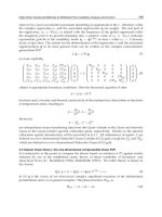
Fig. 7. ZMP trajectory.
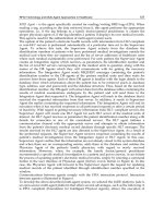
Fig. 8. Video capture of robot motion.
Time [s]
X
ZMP
[m]
1
4
5
3
2
6
8
7
168 Humanoid Robots, New Developments
The torque vector (W
i
) and the optimal gaits for different results of Pareto front solutions are
shown in Fig. 6. The robot posture is straighter, similar to humans, for MCE cost function
(Fig.6(a)). Torque value is low for MCE gait and the torques change smoothly for MTC gait
(Fig. 6(b)). The optimal gait generated by Box 3 solutions satisfies both objective functions.
The energy consumption is increased by 9% but on the other hand the value of MTC cost
function is decreased by 19.2%.
The ZMP trajectory is presented in Fig. 7 for humanoid robot gait generated by Box 3
result. The ZMP is always between the dotted lines, which present the length of the foot.
At the end of the step, the ZMP is at the position ZMP
f
, as shown in Fig. 2. At the
beginning of the step, the ZMP is not exactly at the position ZMP
jump
because of the
foot’s mass. It should be noted that the mass of the lower leg is different when it is in
supporting leg or swing leg.
In order to investigate how the optimized gaits in simulation will perform in real hardware,
we transferred the optimal gaits that satisfy both objective functions on the “Bonten-Maru”
humanoid robot (Fig. 8). The experimental results show that in addition of reduction in
energy consumption, the humanoid robot gait generated by Box 3 solutions was stable. The
impact of the foot with the ground was small.
6. Conclusion
This paper proposed a new method for humanoid robot gait generation based on
several objective functions. The proposed method is based on multiobjective
evolutionary algorithm. In our work, we considered two competing objective
functions: MCE and MTC. Based on simulation and experimental results, we
conclude:
x Multiobjective evolution is efficient because optimal humanoid robot gaits with
completely different characteristics can be found in one simulation run.G
x The nondominated solutions in the obtained Pareto-optimal set are well distributed
and have satisfactory diversity characteristics.G
x The optimal gaits generated by simulation gave good performance when they were
tested in the real hardware of “Bonten-Maru” humanoid robot. G
x The optimal gait reduces the energy consumption and increases the stability during
the robot motion. G
In the future, it will be interesting to investigate if the robot can learn in real time to switch
between different gaits based on the environment conditions. In uneven terrains MTC gaits
will be more
7. References
Becerra, L. B., and Coello, C. A. (2006). Solving Hard Multiobjective Optimization Problems
Using e-Constraint with Cultured Differential Evolution, in Thomas Philip
Runarsson, Hans-Georg Beyer, Edmund Burke, Juan J. Merelo-Guervós, L. Darrell
Whitley and Xin Yao (editors), Parallel Problem Solving from Nature - PPSN IX,
9th International Conference, pp. 543 552, Springer. Lecture Notes in Computer
Science Vol. 4193.
Multicriteria Optimal Humanoid Robot Motion Generation 169
Capi, G., Nasu, Y., Barolli, L., Mitobe, K., and Takeda, K. (2001). Application of
genetic algorithms for biped robot gait synthesis optimization during
walking and going up-stairs, Advanced Robotics Journal, Vol. 15, No. 6, 675-
695.
Capi, G., Nasu, Y., Barolli, L., Mitobe, K., Yamano, .M., and Takeda, K. (2002) A new gait
optimization approach based on genetic algorithm for walking biped robots and a
neural network implementation, Information Processing Society of Japan (IPSJ), Vol.
43, No. 4, 1039-1049.
Capi, G., Nasu, Y., Barolli, L., and Mitobe, K. (2003). Real time gait generation for
autonomous humanoid robots: a case study for walking, Robotics and Autonomous
Systems, Vol. 42, No. 2, 107-116.
Channon, P. H, Pham, D. T., and Hopkins, S. H. (1996). A variational approach to the
optimization of gait for a bipedal robot, Journal of Mechanical Engineering Science,
Vol. 210, 177-186.
Coello, C. A. C. (1999) A comprehensive survey of evolutionary based multiobjective
optimization techniques, Knowledge and Information Systems, Vol. 1, No. 3, pp. 269-
308.
Dias, A. H. F. & De Vasconcelos, J. A. (2002). Multiobjective genetic algorithms applied to
solve optimization problems, IEEE Transactions on Magnetic, Vol. 38, No. 2, 1133-
1136.
Herrera, F., Lozano, M. and Verdegay, J. L. (1998). Tackling real-coded genetic algorithms:
operators and tools for behavioral analysis, Artificial Intelligence Review, Vol. 12, No.
4, 265-319.
Nakano, E., Imamizu, H., Osu, R., Uno, Y. Gomi, H., Yoshioka, T., and Kawato, M. (1999)
Quantitative examinations of internal representations for arm trajectory planning:
minimum commanded torque change model, The Journal of Neurophysiology, Vol.
81, No. 5, 2140-2155.
Nasu, Y., Capi, G., Yamano, M. (2002). “Bonten-Maru I”: Development and Perspectives of a
Humanoid Robot Project, Proc. of Pacific Conference on Manufacturing (PCM2002), pp.
240-245.
Roussel, L., Canudas-de-Wit, C., and Goswami, A. (1998). Generation of energy optimal
complete gait cycles for biped robots, Proc. IEEE Int. Conf. on Robotics and
Automation, pp. 2036-2041.
Sareni, B., Krähenbühl, L. and Nicolas, A. (1998). Niching genetic algorithms for
optimization in electromagnetics-I Fundamentals, IEEE Transactions on Magnetic,
Vol. 34, 2984–2987.
Silva, F. M. and Machado, J. A. T. (1999). Energy analysis during biped walking, Proc. IEEE
Int. Conf. On Robotics and Automation, pp. 59-64.
Srivinas, N. & Deb, K. (1995 ). Multiobjective optimization using non-dominated sorting in
genetic algorithms, Evolutionary Computation, Vol. 2, No. 3, 279-285.
Takeda, K., Nasu, Y., Capi, G., Yamano, M., Barolli, L., Mitobe, K. (2001). A CORBA-Based
approach for humanoid robot control, Industrial Robot-an International Journal,
Vol.28, No.3, 242-250.
Uno, Y., Kawato, M., and Suzuki, R. (1989). Formulation and control of optimal trajectory in
human multijoint arm movement, Biol. Cybernet. Vol. 61, pp. 89-101.
170 Humanoid Robots, New Developments
Vukobratovic, M., Borovac, B., Surla, D. and D. Stokic. (1990). Biped Locomotion, Dynamics,
Stability, Control and Application. Springer-Verlag Berlin.
Zitzler, E., Deb, K., and Thiele, L. (2000). Comparison of multiobjective
evolutionary algorithms: empirical results, Evolutionary Computation, Vol. 8,
No. 2, 173-195.
10
An Incremental Fuzzy Algorithm for
The Balance of Humanoid Robots
Erik Cuevas
1,2
, Daniel Zaldivar
1,2
, Ernesto Tapia
2
and Raul Rojas
2
1
Universidad de Guadalajara, CUCEI,
2
Freie Universität Berlin, Institut für Informatik
Mexico, Germany
1. Introduction
Humanoid robots base their appearance on the human body (Goddard et al., 1992; Kanehira
et al., 2002; Konno et al., 2000). Minimalist constructions have at least a torso with a head,
arms or legs, while more elaborated ones include devices that assemble, for example, human
face parts, such as eyes, mouth, and nose, or even include materials similar to skin.
Humanoid robots are systems with a very high complexity, because they aim to look like
humans and to behave as they do.
Mechanical control, sensing, and adaptive behaviour are the constituting logical parts
of the robot that allow it to “behave” like a human being. Normally, researchers
study these components by modelling only a mechanical part of the humanoid robot.
For example, artificial intelligence and cognitive science researches consider the
robot from the waist up, because its visual sensing is located in its head, and its
behavior with gestures normally uses its face or arms. Some engineers are mostly
interested in the autonomy of the robot and consider it from the waist down. They
develop mathematical models that control the balance of the robot and the
movement of its legs (Miller, 1994; Yamaguchi et al., 1999; Taga et al., 1991),
allowing the robot to walk, one of the fundamental behaviours that characterizes
human beings.
Examples of such mathematical models are static and dynamic walking. The static
walking model controls the robot to maintain its center of gravity (COG) inside a stable
support region, while the dynamic walking model maintains the zero moment point
(ZMP) inside the support region. Kajita et al. (1992) designed and developed an almost
ideal 2-D model of a biped robot. He supposed, for simplicity, that the robot's COG
moves horizontally and he developed a control law for initiation, continuation and
termination of the walking process. Zhen and Shen (1990) proposed a scheme to enable
robot climbing on inclined surfaces. Force sensors placed in the robot's feet detect
transitions of the terrain type, and motor movements correspondingly compensate the
inclination of robot.
The models mentioned above can be, however, computationally very expensive, and
prohibitive for its implementation in microcontrollers. Control algorithms for a
stable walking must be sufficiently robust and smooth, to accomplish a balance
correction without putting in risk the mechanical stability of the robot. This could be
resolved by using a controller that modifies its parameters according to a
172 Humanoid Robots, New Developments
mathematical model, which considers certain performance degree required to offer
the enough smoothness.
Fuzzy Logic is especially advantageous for problems which cannot be easily represented
by a fully mathematical model, because the process is mathematically too complex and
computationally expensive, or some data is either unavailable or incomplete. The real-
world language used in Fuzzy Control also enables the incorporation of approximate
human logic into computers. It allows, for example, partial truths or multi-value truths
within the model. Using linguistic modeling, as opposed to mathematical modeling,
greatly simplifies system design and modification. It generally leads to quicker
development cycles, easy programming, and fairly accurate control. It is important,
however, to underline that fuzzy logic solutions are usually not aimed at achieving the
computational precision of traditional techniques, but aims at finding acceptable solutions
in shorter time.
The Incremental Fuzzy Control algorithm fulfils the robustness and smoothness
requirements mentioned above, even its implementation in microcontrollers. Such an
algorithm is relatively simple and computationally more efficient than other adaptive
control algorithms, because it consists of only four fuzzy rules. The algorithm demonstrates
a smooth balance control response between the walking algorithm and the lateral plane
control: one adaptive gain varies incrementally depending on the required performance
degree.
The objective of this chapter is to describe the incremental fuzzy algorithm, used to
control the balance of lateral plane movements of humanoid robots. This fuzzy control
algorithm is computationally economic and allows a condensed implementation. The
algorithm was implemented in a PICF873 microcontroller. We begin on the next section
with the analysis of the balance problem, and follow later with the description of the
controller structure. Afterwards, we explain important considerations about the
modification of its parameters. Finally, we present experimental results of algorithm, used
on a real humanoid robot, “Dany walker”, developed at the Institut für Informatik of the
Freie Universität Berlin.
2. Robot Structure
The humanoid robot “Dany Walker” used in our research was built only from the waist
down. It consists of 10 low-density aluminium links. They are rotational on the pitch axis at
the hip, knee and ankle. Each link consists of a modular structure. The links form a biped
robot with 10 degrees of freedom, see Fig. 1.
The robot structure and its mass distribution affect directly the dynamic of the
humanoid (Cuevas et al., 2004), therefore, the movement of the Center of Masses
(COM) has a significant influence on the robot stability. In order to achieve static
stability, we placed the COM as low as possible. To such purpose, our design uses
short legs, see Fig. 2
To compensate the disturbances during walking, our construction enables lateral
movements of the robot. Thus, it was possible to control the lateral balance of the robot by
swaying the waist using four motors in the lateral plane: two at the waist and two at the
ankles, see Fig. 3.
An Incremental Fuzzy Algorithm for The Balance of Humanoid Robots 173
Fig. 1 The biped robot “Dany Walker”
Fig. 2. Dany Walker’s COM location.
Fig. 3. Lateral balance of the motors.
COM
Lateral movement
Lateral movement
Waist motor2
Ankle motor2
Waist
motor1
Ankle motor1
174 Humanoid Robots, New Developments
3. Balance control criterion
We used the dynamic walking model to define our balance criterion. It consists of
maintaining the Zero Moment Point (ZMP) inside the support region (Vukobratovic & Juricic,
1969; Vukobratovic, 1973). We implemented a feedback-force system to calculate the ZMP,
and feed it in to the fuzzy PD incremental controller to calculate the ZMP error. Then, the
controller adjusts the lateral robot’s positions to maintain the ZMP point inside of the
support region.
To achieve stable dynamic walking, the change between simple supports phase and double
supports phase should be smooth. In the beginning of the double supports phase, the foot
returns from the air and impacts against the floor, generating strong forces that affect the
walking balance (Cuevas et al., 2005). The intensity of these forces is controlled by imposing
velocity and acceleration conditions on saggital motion trajectories. This is achieved by
using smooth cubic interpolation to describe the trajectories. In this chapter, we only discuss
the control of the lateral motion (balance).
3.1 Zero Moment Point (ZMP)
The ZMP is the point on the ground where the sum of all momentums is zero. Using this
principle, the ZMP is computed as follows:
T
¦¦¦
¦
()
()
ii iii
y
i
y
iii
ZMP
i
i
mz gx mxz I
x
mz g
(1)
,
)(
)(
¦
¦¦¦
i
i
iii
ixixiiii
ZMP
gzm
Izxmygzm
y
T
(2)
where (x
ZMP
, y
ZMP
,0) are the ZMP coordinates, (x
i
,y
i
,z
i
) is the mass center of the link i in the
coordinate system, m
i
is the mass of the link i, and g is the gravitational acceleration. I
ix
and
I
iy
are the inertia moment components,
iy
T
and
ix
T
are the angular velocity around the axes
x and y, taken as a point from the mass center of the link i. The force sensor values are
directly used to calculate the ZM. For the lateral control, it is only necessary to know the
ZMP value for one axis. Thus, the ZMP calculus is simplified using the formula
¦
¦
3
1
3
1
r
ii
i
ZMP
i
i
f
P
f
, (3)
where f
i
represents the force at the i sensor, and r
i
represents the distance between the
coordinate origin and the point where the sensor is located. Figure 4 shows the distribution
of sensors (marked with tree circles) used for each robot‘s foot.
The total ZMP is obtained by the difference between the ZMPs at each foot:
12
_
Z
MP ZMP ZMP
Total P P P
, (4)
where P
ZMP1
is the ZMP for one foot and
2
Z
MP
P
is the ZMP for the other.
Figure 5 shows the ZMP point (black point) for two robot’s standing cases, one before to
give a step (left), and other after give a step (right). The pointed line represents the support
polygon.
An Incremental Fuzzy Algorithm for The Balance of Humanoid Robots 175
Fig. 4. Sensors distribution at the robot’s foot.
Fig. 5. The black point represents the Robot ZMP before giving a step (left), and after giving
a step (right).
4. The Fuzzy PD incremental algorithm.
We propose the fuzzy PD incremental control algorithm, as a variant for the fuzzy PD controller
(Sanchez et al., 1998), to implement the biped balance control. The fuzzy PD incremental control
algorithm consists of only four rules and has the structure illustrated in Fig. 6.
Fig. 6. Fuzzy PD incremental algorithm structure.
The gains G
u
, G
e
and G
r
are determined by tuning and they correspond respectively to the
output gains, the error (ZMP error) and error rate (ZMP rate) gains. The value u* is the
defuzzyficated output or “crisp” output. The value u is
r
1
r
2
r
3
f
3
f
2
f
1
x
0
y
rate
error
u
Fuzzyfication
Control Rules
Defuzzyfication
u
*
G
u
G
r
+
-
Se
t
-
p
oin
t
Incremental gain
-
Process
de/d
t
G
e
P
ZMP1
P
ZM2
Total_P
ZMP
P
ZMP1
P
ZMP2
Total_P
ZMP
y
176 Humanoid Robots, New Developments
T
T
°
°
®
°
°
!
¯
*
*( ) ( 0, 0)
uinc
inc
Gu ife fort G
u
GIncife
(5)
Where e is the error (error*G
e
),
T
is an error boundary selected by tuning, and G
inc
is the
incremental gain obtained adding the increment “Inc”.
Figure 7 shows the flow diagram for the incremental gain of u.
Fig. 7. Flow diagram for the incremental gain of G
u
.
Figure 8 shows the area where the absolute error is evaluated and the controller output is
incremental (u=G
inc
+Inc).
4.1 Fuzzyfication
As is shown in figure 9, there are two inputs to the controller: error and rate. The error is
defined as:
error = setpoint - y (6)
Rate it is defined as it follows:
rate = (ce - pe) / sp (7)
Where ce is the current error, pe is the previous error and sp is the sampling period. Current
and previous error, are referred to an error without gain. The fuzzy controller has a single
incremental output, which is used to control the process
no
Abs(error)>
T
no
yes
G
inc
=G
inc
+Inc
G
inc
=G
u
yes
u =G
inc
* u
*
For t=0, G
inc
=0
u =G
u
* u
*
u
*
An Incremental Fuzzy Algorithm for The Balance of Humanoid Robots 177
Fig. 8. Fuzzy PD incremental absolute error area.
The input an output membership functions for the fuzzy controller are shown in Fig. 9 and
Fig. 10, respectively. Fig. 9 shows that each input has two linguistic terms. For the error
input are: Ge* negative error (en) and Ge* positive error (ep) and for the rate input are:
Gr*negative rate (rn) and Gr * positive rate (rp), while the output fuzzy terms are shown in Fig.
10 and they are: Negative output (on), Zero output (oz) and Positive output (op).
As shown in Fig. 9, the same function is applied for error and rate but with different scaling
factors: Ge and Gr respectively.
H and L are two positive constants to be determined. For convenience we will take H=L to
reduce the number of control parameters to be determined. The membership functions for
the input variables, error and rate, are defined by:
P
(* )
2
e
ep
L G error
L
P
(* )
2
e
en
L G error
L
(8)
P
(* )
2
rp
LGrrate
L
(* )
2
rn
LGrrate
L
P
Fig. 9. Input membership functions.
Abs(error)>
T
Abs(error)>
T
Error + 0-
G
e
*error
G
r
*rate
1.0
G
e
* positive error
G
r
* positive rate
G
e
* negative error
G
r
* negative rate
-L 0 L
178 Humanoid Robots, New Developments
Fig. 10. Input membership functions.
4.2 Fuzzy rules and defuzzyfication.
There exist four rules to evaluate the fuzzy PD incremental controller (Miller 1994):
R1. If error is ep and rate is rp then output is op
R2. If error is ep and rate is rn then output is oz
R3. If error is en and rate is rp then output is oz
R4. If error is en and rate is rn then output is on
The determination of these rules can be accomplished easily if the system evolution is
analyzed in the different operation points. For example, when the error and the rate increase
(rule 1), it means that the system response decreases and moves away from the setpoint, for this
reason it is necessary to apply a positive stimulus that allows to increase the system output. The
figure 11 shows the determination of the different rules based on the system response.
Fig. 11. Determination of the different rules based on the system response (see Text).
0 H-H
Positive Output
Negative Output
Zero Out
p
u
t
Out
p
ut (u*)
t
set
p
oin
t
y
R4
error<0
rate<0
o
n
R3
error<0
rate>0
oz
R1
error>0
rate>0
op
R2
error>0
rate<0
oz
An Incremental Fuzzy Algorithm for The Balance of Humanoid Robots 179
For the fuzzy condensed controller proposed, the input error and rate values ranges can be
represented in 20 input regions (IC), like is shown in Fig. 12. If the membership functions
are evaluated, the 4 control rules, the simplification H=L, and the defuzzyfication is applied
in each one of the 20 inputs combinations, then 9 equations can be obtained (Sanchez et al.,
1998), which can determine the control signal u that should be applied, depending on the
region it is located. In other words, to implement the fuzzy condensed controller, only will
be necessary to know the region in which the inputs variables are located and later evaluate
the corresponding equation for this region. For example, the first equation acts in regions
IC1, IC2, IC5, IC6. The figure 13 shows the control surface of the fuzzy condensed controller
considering H=L=1.
Finally, the defuzzyfication method used is the gravity center, in this case is represented by:
PPP P
PPPP
4() 2() 3() 1()
4() 2() 3() 1()
()0( )()
()
Rx Rx Rx Rx
Rx Rx Rx Rx
HH
u
(9)
5. Real time results
The first test applied to the balance controller was an x-direction impulse. The robot was
standing in balance and then a push in the lateral direction was applied to the biped robot.
Figure 14 shows the evolution of the ZMP value in centimeters during 10 seconds.
Figure 15 shows the error and rate evolution during the application of the x-direction
impulse. The incremental PD fuzzy controller’s parameters were: Ge=2, Gr=2, and Gu=1.
Fig. 12. Input regions.
rate
L-L
L
-L
IC1
error>-rate
IC2
error>rate
IC3
error<rate
IC4
error>-rate
IC5
error<-rate
IC6
error<rate
IC7
error>rate
IC8
error<-rate
IC17
error>L
rate>L
IC10
error>L
0<rate>L
IC9
error>L
-L<rate>L
IC20
error>L
rate<-L
IC11
0<error>L
rate>L
IC12
-L<error>0
rate>L
IC18
error<-L
rate>L
IC13
error>-L
0<rate>L
IC14
error<-L
-L<rate>L
IC19
error<-L
rate<-L
IC15
-L<error<0
rate<-L
IC16
0<error<L
rate<-L
error
180 Humanoid Robots, New Developments
−1
−0.5
0
0.5
1
0
0.2
0.4
0.6
0.8
1
−0.6
−0.4
−0.2
0
0.2
0.4
0.6
error
Control surface
rate
output
Fig. 13. Control surface of the fuzzy condensed controller considering H=L=1.
Fig. 14. ZMP value evolution achieved by the controller, for a x-direction impulse.
An Incremental Fuzzy Algorithm for The Balance of Humanoid Robots 181
Fig. 15. Error and rate evolution for a x-direction impulse.
Finally, a walking test balance was applied to the robot. The robot gave some steps in a flat
surface, while the balance controller compensated the ZMP value. Figure 16 shows the
evolution of the ZMP value (in centimeters) achieved by the controller during 15 seconds.
Figure 17 shows error and rate evolution during the robots walk. The incremental PD fuzzy
controller’s parameters were: Ge=2, Gr=2, and Gu =1.
Fig. 16. ZMP value evolution achieved by the controller during the robot walk.
182 Humanoid Robots, New Developments
Fig. 17. Error and rate evolution during the robot walk.
The motor’s position output was computed by the controller during the walk. It is showed
at Figure 18. This motor’s position value is only just for one waist motor.
Fig. 18. Motor’s position output during the robot walk
An Incremental Fuzzy Algorithm for The Balance of Humanoid Robots 183
6. Conclusion
Figure 11 shows the controller’s performance and response for an x-direction impulse. The
response was fast, approximately 2 seconds, until the controller reached a ZMP value near
to zero. This feature allows the biped robot to gain stability even during walking (figure 13),
maintaining the ZMP always inside the support polygon.
Our experiments with the fuzzy PD incremental controller algorithm demonstrated that it is
computationally economic, all running in a PIC microcontroller, and appropriated for
balance control. The algorithm was successfully used in real-time with the biped robot
“Dany walker” (videos available at
The algorithm proposed in this chapter could be also used in other robots structures with a
different dynamic, and even with other degrees of freedom. It would be only necessary to
adjust the controller’s gain parameters to the particular structure.
We plan to use the information given by an inclinometer along with the ZMP value. In this
case, the goal of the bipedal balance robot control will be to achieve an inclination value of
cero and to maintain the ZMP at the center, or inside of the support polygon.
The bipedal robot used in this work is part of a project that is being developed at the Freie
Universität Berlin.
7. References
Goddard, R.; Zheng, Y. & Hemami, H. (1992). Control of the heel-off to toe-off motion of a
dynamic biped gait, IEEE Trans. Syst. Man. Cayb., 1992, vol.22, no. 1
Kanehira, N.; Kawasaki, T.; Ohta, S.; Isozumi, T.; Kawada, T.; Kanehiro, F.; Kajita, S. &
Kaneko, K. (2002). Design and experiments of advanced module (HRPL-2L) for
humanoid robot (HRP-2) development, Proc. 2002, IEEE-RSJ Int. Conf. Intell. Rob.
Sys. EPFL, Lausanne, Switzerland, 2002, 2455-2460.
Konno, A.; Kato, N.; Shirata, S.; Furuta, T. & Uchiyama, M. (2000). Development of a light-
weight biped humanoid robot in Proc. 2000 IEEE-RSJ Int. Con. Intell. Rob. Sys., 2000,
1565-1570.
Miller, W. (1994). Real-time neural network control of a biped walking robot, IEEE contr.
Syst., vol. 14, 1994, 41-48.
Yamaguchi, J.; Soga, E.; Inoue, S. & Takanishi, A. (1999). Development of a biped robot-
control method of a whole body cooperative dynamic biped walking, in Proc. 1999
IEEE Int. Conf. Robot. And Aut., Detroit, Michigan, 1999, 368-374.
Taga, G.; Yamaguchi Y. & Shimizu, H. (1991). Self-organized control of bipedal locomotion
by neural oscilators in unpredictable environment, Biol. Cyb. 65 1991, 147-165.
Kajita, S.; Yamaura, T. & Kobayashi, A. (1992). Dynamic walking control of a biped robot
along a potiential energy conserving orbit, IEEE Trans. Robot Automat. Vol. 8, no. 4,
1992. pp 437-438.
Zheng, Y. & Shen, J. (1990). Gait synthesis for the SD-2 biped robot to climb sloped surface,
IEEE, Trans. Robot Automat. Vol 6, no 1. , 1990, 86-96.
Cuevas, E.; Zaldívar, D. & Rojas, R. (2004). Bipedal robot description, Technical Report B-03-
19, Freie Universität Berlin, Fachbereich Mathematik und Informatik, Berlin, Germany,
2004.
Vukobratovic, M. & Juricic, D. (1969). Contribution to the synthesis of biped gait, IEEE
Trans. Bio-Med. Eng., vol. BME-16, no. 1 , 1969, 1-6.
184 Humanoid Robots, New Developments
Vukobratovic, M. (1973). How to control artificial anthropomorphic system, IEEE Trans.
Syst. Man. Cyb., vol. SMC-3, no. 5, 1973, 497-507.
Cuevas, E.; Zaldívar, D. & Rojas, R. (2005). Dynamic Control Algorithm for a Biped Robot,
The 7th IASTED International Conference on CONTROL AND
APPLICATIONS,Cancún, México, CA 2005.
Sanchez, E.; Nuno, L.; Hsu, Y. & Guanrong, C. (1998). Real Time Fuzzy Swing-up Control
for an Underactuated Robot, JCIS '98 Proceedings,Vol 1 , N.C., USA, 1998.
11
Spoken Language and Vision for Adaptive
Human-Robot Cooperation
Peter Ford Dominey
CNRS – University of Lyon
France
1. Introduction
In order for humans and robots to cooperate in an effective manner, it must be possible for
them to communicate. Spoken language is an obvious candidate for providing a means of
communication. In previous research, we developed an integrated platform that combined
visual scene interpretation with speech processing to provide input to a language learning
model. The system was demonstrated to learn a rich set of sentence-meaning mappings that
could allow it to construct the appropriate meanings for new sentences in a generalization
task. We subsequently extended the system not only to understand what it hears, but also to
describe what it sees and to interact with the human user. This is a natural extension of the
knowledge of sentence-to-meaning mappings that is now applied in the inverse scene-to-
sentence sense (Dominey & Boucher 2005). The current chapter extends this work to analyse
how the spoken language can be used by human users to communicate with a Khepera
navigator, a Lynxmotion 6DOF manipulator arm, and the Kawada Industries HRP-2
Humanoid, to program the robots’ behavior in cooperative tasks, such as working together
to perform an object transportation task, or to assemble a piece of furniture. In this
framework, a system for Spoken Language Programming (SLP) is presented. The objectives
of the system are to 1. Allow the human to impart knowledge of how to accomplish a
cooperative task to the robot, in the form of a sensory-motor action plan. 2. To allow the user
to test and modify the learned plans. 3. To do this in a semi-natural and real-time manner
using spoken language and visual observation/demonstration. 4. When possible, to exploit
knowledge from studies of cognitive development in making implementation choices. With
respect to cognitive development, in addition to the construction grammar model, we also
exploit the concept of “shared intentions” from developmental cognition as goal-directed
action plans that will be shared by the human and robot during cooperative activities.
Results from several experiments with the SLP system employed on the different platforms
are presented. The SLP is evaluated in terms of the changes in efficiency as revealed by task
completion time and number of command operations required to accomplish the tasks.
Finally, in addition to language, we investingate how vision can be used by the robot as well
to observe human activity in order to able to take part in the observed activities. At the
interface of cognitive development and robotics, the results are interesting in that they (1)
provide concrete demonstration of how cognitive science can contribute to human-robot
interaction fidelity, and (2) they suggest how robots might be used to experiment with
theories on the implementation of cognition in the developing human.
186 Humanoid Robots, New Developments
2. Language and Meaning
Crangle and Suppes (1994) stated: “(1) the user should not have to become a programmer, or
rely on a programmer, to alter the robot’s behavior, and (2) the user should not have to learn
specialized technical vocabularies to request action from a robot.” Spoken language
provides a very rich and direct means of communication between cooperating humans
(Pickering & Garrod 2004). Language essentially provides a vector for the transmission of
meaning between agents, and should thus be well adapted for allowing humans to transmit
meaning to robots. This raises technical issues of how to extract meaning from language.
Construction grammar (CxG) provides a linguistic formalism for achieving the required link
from language to meaning (Goldberg 2003). Indeed, grammatical constructions define the
direct mapping from sentences to meaning. Meaning of a sentence such as (1) is represented
in a predicate-argument (PA) structure as in (2), based on generalized abstract structures as
in (3). The power of these constructions is that they employ abstract argument “variables”
that can take an open set of values.
(1) John put the ball on the table.
(2) Transport(John, Ball, Table)
(3) Event(Agent, Object, Recipient)
We previously developed a system that generates PA representations (i.e. meanings) from
video event sequences. When humans performed events and described what they were
doing, the resulting <sentence, meaning> input pairs allowed a separate learning system to
acquire a set of grammatical constructions defining the sentences. The resulting system
could describe new events and answer questions with the resulting set of learned
grammatical constructions (Dominey & Boucher 2005).
PA representations can be applied to commanding actions as well as describing them.
Hence the CxG framework for mapping between sentences and their PA meaning can be
applied to action commands as well. In either case, the richness of the language employed
will be constrained by the richness of the perceptual and action PA representations of the
target robot system. In the current research we examine how simple commands and
grammatical constructions can be used for action command in HRI. Part of the challenge is
to define an intermediate layer of language-commanded robot actions that are well adapted
to a class of HRI cooperation tasks.
This is similar to the language-based task analysis in Lauria et al. (2002). An essential part of
the analysis we perform concerns examining a given task scenario and determining the set
of action/command primitives that satisfy two requirements. 1. They should allow a logical
decomposition of the set of tasks into units that are neither too small (i.e. move a single
joint) nor too large (perform the whole task). 2. They should be of general utility so that
different tasks can be performed with the same set of primitives.
3. Spoken Language Programming
For some tasks (e.g. navigating with a map) the sequence of human and robot actions
required to achieve the task can be easily determined before beginning execution. Other
tasks may require active exploration of the task space during execution in order to find a
solution. In the first case, the user can tell the robot what to do before beginning
execution, while in the second, instruction will take place during the actual execution of
the task.
Spoken Language and Vision for Adaptive Human-Robot Cooperation 187
In this context, (Lauria et al. 2002) asked naïve subjects to provide verbal instructions to a
robot in a miniature-town navigation task. Based on an analysis of the resulting speech
corpora, they identified a set of verbal action chunks that could map onto robot control
primitives. More recently, they demonstrated the effectiveness of navigation instructions
translated into these primitive procedures for actual robot navigation (Kyriacou et al. 2005).
This research indicates the importance of implementing the mapping between language and
behavioural primitives for high-level natural language instruction or programming. The
current study extends these results by introducing a conditional (e.g. if-then) component to
the programming.
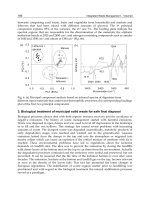
Fig. 1. Khepera robot and object transportation scenario. A. Physical set up. B. Labeled
schematic representation.
Figure 1 illustrates a given scenario for HRI. In Figure 1A we see the Khepera robot on a
table top, and in Figure 1B a schematic of the robot (represented as the gray disc) in a two
arm maze. Consider a task in which User1 sends the Khepera robot to User2 who gives it an
object to transport back to User1. Getting to User2 requires a conditional choice between two
paths based on the location of an obstacle that is not known in advance, at the locations
indicated by the dotted lines. Once the robot determines the location of the obstacle, it
should choose the path that is not blocked, and make its way to the end of the arm. There it
should turn around, and wait for User2, to place an object on its carrying surface. When
User2 has performed this, User1 will say “continue” and the robot should then return to the
beginning of the maze arm where User1 will take the transported block, and the process
then continues.
On-Line Commanding: The simplest solution for controlling the robot in this task, which
involves no learning, is for User1 simply to tell the robot what to do, step by step.
Depending on whether the obstacle is at the left or right arm position, the human User1
would decide whether to tell the robot to take the right or left pathway. Likewise, once at
the end point, User1 would wait until the User2 placed the object before commanding the
robot to turn around and come back.
Programming a Pre-Specified Problem: Again, in many cases, the problem is known to the
user in advance (possibly because the user has now “walked” the robot through the
problem as just described) and can be specified prior to execution.
The objective of SLP is to provide a framework in which non-specialist humans can
explain such a task to a robot, using simple spoken language. While the task
described above remains relatively simple, explaining it to the robot already levies
several interesting requirements on the system, and meeting these requirements will
provide a fairly general and robust capability for SLP. In particular, this task requires
AAA
R
L
B
Possible
obstacle
R
L
B
R
L
B
Possibl
obstacle
188 Humanoid Robots, New Developments
the following: (1) The user should be able to provide a sequence of primitive
commands that will be executed in a particular order. (2) The user should be able to
specify conditional execution, based on the values of robot sensors. (3) The user
should be able to tell the robot that at a certain point it should wait for some sensory
event to occur before proceeding with its sequence execution., as demonstrated
below.
In addition, for tasks that become increasingly long and complex, the user may make
mistakes in his/her initial specification of the task, so the SLP system should allow the user
to test, “debug” and modify programs. That is, once the user has specified the program, he
should be able to execute it and – if there is a problem – modify it in a simple and
straightforward manner.
On-line Commanding with Repetitive Sub-Tasks: On-line commanding allows the user to
be responsive to new situations, and to learn him/herself by taking the robot through a
given task or tasks. On the other hand, for tasks that are well defined, the user can program
the robot as defined above. In between these two conditions there may arise situations in
which during the course of solving a cooperative problem with the robot, the user comes to
see that despite the “open endedness” of a given problem set, there may repetitive subtasks
that occur in a larger context. In this type of situation, the human user may want to teach the
robot about the repetitive part so this can be executed as an autonomous subroutine or
“macro” while the user still remains in the execution loop for the components that require
his/her decision.
Fig. 2. Human-Robot cooperation in a furniture construction task. A. Robot takes a table leg
from User2. B. Robot hands the leg to User1. C. Robot holds the table steady while User1
attaches the leg.
Figure 2 illustrates such an HRI scenario that involves two humans and the HRP-2
cooperating in the construction of a small table. The construction task will involve fixing the
legs to the surface of the table with wood screws. User1 on the left interacts with the robot
and with User2 on the right via spoken language.
User1 will command the robot to prepare to receive one of the table legs that will be passed
to it by User2. The robot waits until it receives a “continue” signal from User1, and will then
pass the leg to User1 who will take the leg, and then ask the robot to hold the table top
steady allowing User1 to attach the leg to the table. User1 then tells the robot to release the
table. At this point, the first leg has been fixed to the table, and the “get the leg and attach it”
sequence can be repeated. This task thus has a repeating subsequence that can be applied to
each of the four legs of the table. Experiments below address this task. These experiments
identify the utility of a more complex command structure based on grammatical
constructions.
B
C
A B C
Spoken Language and Vision for Adaptive Human-Robot Cooperation 189
Fig. 3. Cooperative manipulation task scenario. User asks for screws from locations
identified by color. While robot holds the plastic “table” (as illustrated) the user can insert
the screws into the table (see inset).
Influence of Robot Command Structure on Language: Part of the central principal of
construction grammar (and the related domain of cognitive linguistics) is that human
language is made up of a structured inventory of grammatical constructions (Goldberg
2003). These constructions reflect the meaning of prototypical events that are basic to
human experience. Thus for example the “ditransitive” construction involves one agent
transferring an object to another, as in “John gave Mary the ball.” From a robotics
perspective, the action predicate-argument Move(Object, Location) can thus be considered
as a template for a motor program that allows the use of constructions of the form “Give
the X to Y”. This robot PA involves localizing X and Y, and then grasping X and
transporting the effector to Y to transfer X to Y. To the extent that such an action PA
(APA) is built into the repertoire of the robot (or to the extent that it can be built up from
primitives like localize(X), transport-to(X) etc.) rich grammatical constructions can be
used to generate and interpret sentences like “give me the red block,” or “put the blue
block next to the red block” for robot control.
Figure 3 illustrates a simplified version of the table construction scenario that uses the
Lynx6 arm for cooperative manipulation in a construction task. Experiments below
examine cooperative construction with the Lynx6 based on lessons learned from the
HRP-2 experiments, including more complex commands based on grammatical
constructions.
4. Implementation of Spoken Language Programming
Because of the potential influence that the robot itself will have on spoken language
interaction, we chose to develop a core SLP system, and then to adapt the system to three
different robot platforms the K-Team Khepera, the LynxMotion Lynx 6 DOF manipulator
arm, and the Kawada Industries HRP-2 Humanoid. This allows us to explore the navigation
vs. manipulation dimension, and within the manipulation dimension the Lynx allows for
rapid prototyping while the HRP-2 allows for a much more robust and human-scale human-
robot interaction.
Spoken Language Programming Core: The core SLP system is presented in Figures 4 and 5,
and Table 1. The core system provides the command, conditional control, and
programming/teaching capabilities based on spoken language.
190 Humanoid Robots, New Developments
Fig. 4. Spoken Language Programming Architecture. The fundamental unit of meaning is
the predicate-argument (PA) representation. APA – Action Predicate-Argument
representation. PPA – Perceptual Predicate-Argument representation. Spoken language
commands are interpreted as individual words or grammatical constructions, and the
command and possible arguments are extracted in Sentence to PA Meaning. The robot level
commands (CMD) are extracted by the PA manager. World Model includes specification of
object locations, and related state information. Robot commands are then issued to the
Controller to effect the commands. Conditional commands including IF CONDITION
OTHERWISE, and WAIT are implemented as part of the Conditional Execution. Learning-
related commands LEARN, OK/SAVE-MACRO, RUN MACRO are handled by the
Sequence Encoding and Retrieval function. Event perception and description, provided by
PA Meaning to Sentence are implemented in Dominey & Boucher (2005).
Dialog management and spoken language processing (voice recognition, and synthesis) is
provided by an “off the shelf” public domain product, the CSLU Rapid Appication
Development (RAD) Toolkit ( RAD provides a state-based
dialog system capability, in which the passage from one state to another occurs as a function
of recognition of spoken words or phrases; or evaluation of Boolean expressions. Figure 5
illustrates the major dialog states.
Fig. 5. Major Dialog States
In Figure 5, when the system starts in the “Mode Select” state it asks the user “Shall we learn
by planning or by demonstration?”
Learning by Demonstration: If the user replies “demonstration” (note: In all dialogs,
human responses will be indicated by italics) then the system transitions to the
“Direct” state, and interrogates the subject with “Now what?” The user can reply with
one of the robot-specific motor commands, which the robot will execute and then
again prompt “Now what?” In the course of this direct interaction, if the user
Mode
Selec
t
Plan
Edi
t
Run
New
Q
ui
t
Direc
t
Star
t
Spoken Language and Vision for Adaptive Human-Robot Cooperation 191
determines that there is a repetitive component in the task, as illustrated in the
discussion of Figure 2, above, the user can invoke the “Learn” command. This
indicates to the system to begin to store the subsequent commands. When the
repetitive subsequence has been performed, the user then issues the command “OK”
and the subsequence is stored, and can then be executed in-line with the command
“Macro”. This learning, in which the user “demonstrates” the performance by
directing the robot through the execution is illustrated in Exps 3-5.
Learning by Planning: In Figure 5, when the system starts in the “Mode Select” state it asks
the user “Shall we learn by planning or by demonstration?” If the user replies “planning” then
the system transitions to the “Plan” state, and interrogates the subject with “Shall we make a
new plan, run the old plan, edit it or quit ?”
If the user replies “New plan” then the system continuously interrogates the user with “now
what?,” with the user responding each time with the next motor command or conditional
command until the user replies “stop.” In this manner, command by command without
execution, the user specifies the planned program using spoken language. After “stop”, the
plan is stored, and the system returns to the Plan state. Here, the user can now run the plan
to see how it works. If the user detects that there is a problem with one of the elements in
the stored plan, at the “Plan” state, he has the option of saying that he wants to “edit” the
plan.
Editing Learned Programs: When the system enters the Edit state, it displays the plan
graphically as a list of commands and corresponding conditions, and then ask the user what
he wants to modify. The user can then respond with a two word phrase in which the first
word is “action” or “condition”, and the second word is the number of the action or
condition in question. The system then asks the user for the new value for that component,
and then again asks what the user wants to modify. When the editing is finished, the system
then returns to the Plan state where the user can either execute the modified plan, or do
something else.
Conditional Execution: In addition to the learning-related commands, we have also
identified the requirement for commands related to conditional behavior execution and
control. These commands are specified in Table 1. Perhaps the most obvious of these the “if
–then-else” construction.
Conditional Commands Effects / Correspondence
If condition Begin a conditional segment
Otherwise End a conditional segment
Wait condition Interrupt execution until condition is met
Continue User command to proceed when waiting This is one of
the conditions for wait.
Learning-Related Commands
Learn Begin macro learning
Ok/Stop End macro learning
Macro Run stored macro
Table 1. Conditional and Learning-Related Commands.
Indeed this is the first concrete example of the use of a multi-word construction. When the
“if condition” construciton is issued, the user specifies the “if” and the corresponding
condition in the same utternence (e.g. “if left clear”), and the “if” and the “left clear”