Industrial Machinery Repair Part 6 potx
Bạn đang xem bản rút gọn của tài liệu. Xem và tải ngay bản đầy đủ của tài liệu tại đây (521.89 KB, 35 trang )
Compressors 159
the periodic drainage of low points in the piping and separators, as well as
inspection of automatic drain traps.
Pressure-Relief Valves
All reciprocating compressors must be fitted with pressure relief devices
to limit the discharge or interstage pressures to a safe maximum for the
equipment served. Always install a relief valve that is capable of bypassing
the full-load capacity of the compressor between its discharge port and the
first isolation valve. The safety valves should be set to open at a pressure
slightly higher than the normal discharge-pressure rating of the compressor.
For standard 100- to 115-psig two-stage air compressors, safety valves are
normally set at 125 psig.
The pressure-relief safety valve is normally situated on top of the air reser-
voir, and there must be no restriction on its operation. The valve is usually
of the “huddling chamber” design, in which the static pressure acting on its
disk area causes it to open. Figure 8.15 illustrates how such a valve func-
tions. As the valve pops, the air space within the huddling chamber between
View A
closed
View B
cracked
View C
Relieving
4. When the valve setting
is reached, the poppet “opens”
limiting pressure in upper
chamber.
7. Vent connection
permits unloading pum
p
through relief valve.
3. Spring holds
piston closed.
1. Inlet pressure
here
2. Is sensed above
piston and at pilot valve
through orifice in piston.
6. Piston moves up to
divert pump output
directly to tank.
5. When this pressure
is 20 psi higher than in
upper chamber
Figure 8.15 Illustrates how a safety valve functions
160 Compressors
the seat and blowdown ring fills with pressurized air and builds up more
pressure on the roof of the disk holder. This temporary pressure increases
the upward thrust against the spring, causing the disk and its holder to fully
pop open.
Once a predetermined pressure drop (i.e., blowdown) occurs, the valve
closes with a positive action by trapping pressurized air on top of the
disk holder. Raising or lowering the blowdown ring adjusts the pressure-
drop setpoint. Raising the ring increases the pressure-drop setting, while
lowering it decreases the setting.
Operating Methods
Compressors can be hazardous to work around because they have moving
parts. Ensure that clothing is kept away from belt drives, couplings, and
exposed shafts. In addition, high-temperature surfaces around cylinders
and discharge piping are exposed. Compressors are notoriously noisy, so
ear protection should be worn. These machines are used to generate high-
pressure gas so, when working around them, it is important to wear safety
glasses and to avoid searching for leaks with bare hands. High-pressure leaks
can cause severe friction burns.
Troubleshooting
Compressors can be divided into three classifications: centrifugal, rotary,
and reciprocating. This section identifies the common failure modes for
each.
Centrifugal
The operating dynamics of centrifugal compressors are the same as for other
centrifugal machine-trains. The dominant forces and vibration profiles are
typically identical to pumps or fans. However, the effects of variable load and
other process variables (e.g., temperatures, inlet/discharge pressure, etc.)
are more pronounced than in other rotating machines. Table 8.1 identifies
the common failure modes for centrifugal compressors.
Aerodynamic instability is the most common failure mode for centrifugal
compressors. Variable demand and restrictions of the inlet-air flow are com-
mon sources of this instability. Even slight variations can cause dramatic
changes in the operating stability of the compressor.
Compressors 161
Table 8.1 Common failure modes of centrifugal compressors
THE PROBLEM
THE CAUSES
Excessive vibration
Compressor surges
Loss of discharge pressure
Low lube oil pressure
Excessive bearing oil drain temp.
Units do not stay in alignment
Persistent unloading
Water in lube oil
Motor trips
Bearing lube oil orifice missing or
plugged
•
Bent rotor (caused by uneven heating
and cooling)
• •
Build-up of deposits on diffuser •
Build-up of deposits on rotor • •
Change in system resistance • •
Clogged oil strainer/filter •
Compressor not up to speed •
Condensate in oil reservoir •
Damaged rotor •
Dry gear coupling •
Excessive bearing clearance •
Excessive inlet temperature
•
Failure of both main and auxiliary oil
pumps
•
Faulty temperature gauge or switch • • •
Continued
162 Compressors
Table 8.1 continued
THE PROBLEM
THE CAUSES
Excessive vibration
Compressor surges
Loss of discharge pressure
Low lube oil pressure
Excessive bearing oil drain temp.
Units do not stay in alignment
Persistent unloading
Water in lube oil
Motor trips
Improperly assembled parts • • •
Incorrect pressure control valve
setting
•
Insufficient flow •
Leak in discharge piping
•
Leak in lube oil cooler tubes or tube
sheet
•
Leak in oil pump suction piping •
Liquid “slugging” • •
Loose or broken bolting •
Loose rotor parts •
Oil leakage •
Oil pump suction plugged •
Oil reservoir low level
•
Operating at low speed w/o auxiliary
oil pump
•
Operating in critical speed range •
Compressors 163
Table 8.1 continued
THE PROBLEM
THE CAUSES
Excessive vibration
Compressor surges
Loss of discharge pressure
Low lube oil pressure
Excessive bearing oil drain temp.
Units do not stay in alignment
Persistent unloading
Water in lube oil
Motor trips
Operating in surge region •
Piping strain •
• • • •
Poor oil condition •
Relief valve improperly set or stuck
open
•
Rotor imbalance • •
Rough rotor shaft journal surface
• • •
Shaft misalignment •
•
Sympathetic vibration
• • •
Vibration •
Warped foundation or baseplate • •
Wiped or damaged bearings • •
Worn or damaged coupling
•
Entrained liquids and solids also can affect operating life. When dirty air
must be handled, open-type impellers should be used. An open design
provides the ability to handle a moderate amount of dirt or other solids
in the inlet-air supply. However, inlet filters are recommended for all
164 Compressors
applications, and controlled liquid injection for cleaning and cooling should
be considered during the design process.
Rotary-Type, Positive Displacement
Table 8.2 lists the common failure modes of rotary-type, positive-
displacement compressors. This type of compressor can be grouped into
two types: sliding vane and rotary screw.
Sliding Vane Compressors
Sliding-vane compressors have the same failure modes as vane-type pumps.
The dominant components in their vibration profile are running speed,
vane-pass frequency, and bearing-rotation frequencies. In normal operation,
the dominant energy is at the shaft’s running speed. The other frequency
components are at much lower energy levels. Common failures of this type
of compressor occur with shaft seals, vanes, and bearings.
Shaft Seals
Leakage through the shaft’s seals should be checked visually once a week
or as part of every data-acquisition route. Leakage may not be apparent
from the outside of the gland. If the fluid is removed through a vent, the
discharge should be configured for easy inspection. Generally, more leakage
than normal is the signal to replace a seal. Under good conditions, they have
a normal life of 10,000 to 15,000 hours and should routinely be replaced
when this service life has been reached.
Vanes
Vanes wear continuously on their outer edges and, to some degree, on the
faces that slide in and out of the slots. The vane material is affected some-
what by prolonged heat, which causes gradual deterioration. Typical life
expectancy of vanes in 100-psig services is about 16,000 hours of operation.
For low-pressure applications, life may reach 32,000 hours.
Replacing vanes before they break is extremely important. Breakage during
operation can severely damage the compressor, which requires a complete
overhaul and realignment of heads and clearances.
Bearings
In normal service, bearings have a relatively long life. Replacement after
about six years of operation is generally recommended. Bearing defects are
usually displayed in the same manner in a vibration profile as for any rotating
machine-train. Inner and outer race defects are the dominant failure modes,
but roller spin also may contribute to the failure.
Compressors 165
Table 8.2 Common failure modes of rotary-type, positive-displacement compressors
THE PROBLEM
THE CAUSES
No air/gas delivery
Insufficient discharge pressure
Insufficient capacity
Excessive wear
Excessive heat
Excessive vibration and noise
Excessive power demand
Motor trips
Elevated motor temperature
Elevated air/gas temperature
Air leakage into suction piping
or shaft seal
• • •
Coupling misaligned • • • • •
Excessive discharge pressure
• • • • • •
Excessive inlet
temperature/moisture
•
Insufficient suction air/gas
supply
• • • • •
Internal component wear
• • •
Motor or driver failure
•
Pipe strain on compressor
casing
• • • • •
Relief valve stuck open or set
wrong
• •
Rotating element binding • • • • • •
Solids or dirt in inlet air/gas
supply
•
Speed too low • • •
Suction filter or strainer clogged
• • • • •
Wrong direction of rotation
• • •
166 Compressors
Rotary Screw
The most common reason for compressor failure or component damage
is process instability. Rotary-screw compressors are designed to deliver a
constant volume and pressure of air or gas. These units are extremely
susceptible to any change in either inlet or discharge conditions. A slight
variation in pressure, temperature, or volume can result in instantaneous
failure. The following are used as indices of instability and potential
problems: rotor mesh, axial movement, thrust bearings, and gear mesh.
Rotor Mesh
In normal operation, the vibration energy generated by male and female
rotor meshing is very low. As the process becomes unstable, the energy due
to the rotor-meshing frequency increases, with both the amplitude of the
meshing frequency and the width of the peak increasing. In addition, the
noise floor surrounding the meshing frequency becomes more pronounced.
This white noise is similar to that observed in a cavitating pump or unstable
fan.
Axial Movement
The normal tendency of the rotors and helical timing gears is to generate
axial shaft movement, or thrusting. However, the extremely tight clearances
between the male and female rotors do not tolerate any excessive axial
movement, and therefore, axial movement should be a primary monitoring
parameter. Axial measurements are needed from both rotor assemblies. If
there is any increase in the vibration amplitude of these measurements, it
is highly probable that the compressor will fail.
Thrust Bearings
While process instability can affect both the fixed and float bearings, the
thrust bearing is more likely to show early degradation as a result of process
instability or abnormal compressor dynamics. Therefore, these bearings
should be monitored closely, and any degradation or hint of excessive axial
clearance should be corrected immediately.
Gear Mesh
The gear mesh vibration profile also provides an indication of prolonged
compressor instability. Deflection of the rotor shafts changes the wear pat-
tern on the helical gear sets. This change in pattern increases the backlash
in the gear mesh, results in higher vibration levels, and increases thrusting.
Compressors 167
Reciprocating, Positive Displacement
Reciprocating compressors have a history of chronic failures that include
valves, lubrication system, pulsation, and imbalance. Table 8.3 identifies
common failure modes and causes for this type of compressor.
Like all reciprocating machines, reciprocating compressors normally gen-
erate higher levels of vibration than centrifugal machines. In part, the
increased level of vibration is due to the impact as each piston reaches top
dead center and bottom dead center of its stroke. The energy levels also are
influenced by the unbalanced forces generated by nonopposed pistons and
looseness in the piston rods, wrist pins, and journals of the compressor. In
most cases, the dominant vibration frequency is the second harmonic (2X)
of the main crankshaft’s rotating speed. Again, this results from the impact
that occurs when each piston changes directions (i.e., two impacts occur
during one complete crankshaft rotation).
Valves
Valve failure is the dominant failure mode for reciprocating compressors.
Because of their high cyclic rate, which exceeds 80 million cycles per year,
inlet and discharge valves tend to work harder and crack.
Lubrication System
Poor maintenance of lubrication-system components, such as filters and
strainers, typically causes premature failure. Such maintenance is crucial to
reciprocating compressors because they rely on the lubrication system to
provide a uniform oil film between closely fitting parts (e.g., piston rings
and the cylinder wall). Partial or complete failure of the lube system results
in catastrophic failure of the compressor.
Pulsation
Reciprocating compressors generate pulses of compressed air or gas that
are discharged into the piping that transports the air or gas to its point(s) of
use. This pulsation often generates resonance in the piping system, and
pulse impact (i.e., standing waves) can severely damage other machin-
ery connected to the compressed-air system. While this behavior does not
cause the compressor to fail, it must be prevented to protect other plant
equipment. Note, however, that most compressed-air systems do not use
pulsation dampers.
168 Compressors
Table 8.3 A-E in electronic files
THE PROBLEM
THE CAUSES
Air discharge temperature above normal
Carbonaceous deposits abnormal
Compressor fails to start
Compressor fails to unload
Compressor noisy or knocks
Compressor parts overheat
Crankcase oil pressure low
Crankcase water accumulation
Delivery less than rated capacity
Discharge pressure below normal
Excessive compressor vibration
Intercooler pressure above normal
Intercooler pressure below normal
Intercooler safety valve pops
Motor over-heating
Oil pumping excessive (single-acting compressor)
Operating cycle abnormally long
Outlet water temperature above normal
Piston ring, piston, cylinder wear excessive
Piston rod or packing wear excessive
Receiver pressure above normal
Receiver safety valve pops
Starts too often
Valve wear and breakage normal
Air discharge temperature too high • •
Air filter defective
•
• • •
Air flow to
fan blocked
• • •
Air leak into pump suction •
Ambient temperature too high • • • •
Assembly incorrect •
Compressors 169
Bearings need adjustment or renewal • • • •
Belts slipping
• • •
Belts too tight
• • •
Centrifugal pilot valve leaks •
Check or discharge valve defective •
Control air filter, strainer clogged
•
Control air line clogged
•
Control air pipe leaks
• •
Crankcase oil pressure too high •
Crankshaft end play too great •
Cylinder, head, cooler dirty • •
Cylinder, head, intercooler dirty
• •
Cylinder (piston) worn or scored
• •
• • • • • •H •L •H •L • • •H •H
Detergent oil being used (3) •
Demand too steady (2) •
Dirt, rust entering cylinder
• • • •
170 Compressors
Table 8.3 continued
THE PROBLEM
THE CAUSES
Air discharge temperature above normal
Carbonaceous deposits abnormal
Compressor fails to start
Compressor fails to unload
Compressor noisy or knocks
Compressor parts overheat
Crankcase oil pressure low
Crankcase water accumulation
Delivery less than rated capacity
Discharge pressure below normal
Excessive compressor vibration
Intercooler pressure above normal
Intercooler pressure below normal
Intercooler safety valve pops
Motor over-heating
Oil pumping excessive (single-acting compressor)
Operating cycle abnormally long
Outlet water temperature above normal
Piston ring, piston, cylinder wear excessive
Piston rod or packing wear excessive
Receiver pressure above normal
Receiver safety valve pops
Starts too often
Valve wear and breakage normal
Discharge line restricted • •
Discharge pressure above
rating
• •
• • • • • • • • • • • • •
Electrical conditions wrong • •
Excessive number of starts •
Excitation inadequate • •
Foundation bolts loose • •
Compressors 171
Foundation too small
•
Foundation uneven-unit rocks • •
Fuses blown
•
Gaskets leak
• • • • • • •H •L •H •L • •H •H
Gauge defective • • • • •
Gear pump worn/defective •
Grout, improperly placed •
Intake filter clogged •
•
•
• • • • • •
Intake pipe restricted, too
small, too long
•
• • • • • • • •
Intercooler, drain more often
•
Intercooler leaks •
Intercooler passages clogged • •
Intercooler pressure too high
•
Intercooler vibrating •
Leveling wedges left under
compressor
•
Liquid carry-over • • • • •
172 Compressors
Table 8.3 continued
THE PROBLEM
THE CAUSES
Air discharge temperature above normal
Carbonaceous deposits abnormal
Compressor fails to start
Compressor fails to unload
Compressor noisy or knocks
Compressor parts overheat
Crankcase oil pressure low
Crankcase water accumulation
Delivery less than rated capacity
Discharge pressure below normal
Excessive compressor vibration
Intercooler pressure above normal
Intercooler pressure below normal
Intercooler safety valve pops
Motor over-heating
Oil pumping excessive (single-acting compressor)
Operating cycle abnormally long
Outlet water temperature above normal
Piston ring, piston, cylinder wear excessive
Piston rod or packing wear excessive
Receiver pressure above normal
Receiver safety valve pops
Starts too often
Valve wear and breakage normal
Location too humid and damp
•
Low oil pressure relay open
•
Lubrication inadequate • • • • • • • •
Motor overload relay tripped •
Motor rotor loose on shaft • •
Motor too small • •
Compressors 173
New valve on worn seat
•
“Off ” time insufficient • • •
Oil feed excessive • • • •
Oil filter or strainer clogged •
Oil level too high •
•
• • •
Oil level too low
•
•
Oil relief valve defective
•
Oil viscosity incorrect
•
•
• •
•
•
• • •
Oil wrong type •
Packing rings worn, stuck, broken •
Piping improperly supported
•
Piston or piston nut loose
•
Piston or ring drain hole clogged
•
Piston ring gaps not staggered
•
Piston rings worn, broken, or stuck • • • • • • • •H •L •H •L • • •H •H
Piston-to-head clearance too small
•
174 Compressors
Table 8.3 continued
THE PROBLEM
THE CAUSES
Air discharge temperature above normal
Carbonaceous deposits abnormal
Compressor fails to start
Compressor fails to unload
Compressor noisy or knocks
Compressor parts overheat
Crankcase oil pressure low
Crankcase water accumulation
Delivery less than rated capacity
Discharge pressure below normal
Excessive compressor vibration
Intercooler pressure above normal
Intercooler pressure below normal
Intercooler safety valve pops
Motor over-heating
Oil pumping excessive (single-acting compressor)
Operating cycle abnormally long
Outlet water temperature above normal
Piston ring, piston, cylinder wear excessive
Piston rod or packing wear excessive
Receiver pressure above normal
Receiver safety valve pops
Starts too often
Valve wear and breakage normal
Pulley or flywheel loose
• •
Receiver, drain more often •
Receiver too small •
Regulation piping clogged •
Resonant pulsation (inlet or
discharge)
• • • • •
Rod packing leaks • • • • •
Compressors 175
Rod packing too tight •
Rod scored, pitted, worn
•
Rotation wrong • • •
Runs too little (2) •
Safety valve defective • • •
Safety valve leaks • • • • • •
Safety valve set too low
• •
Speed demands exceed rating
•
Speed lower than rating
• •
Speed too high • • • • • •
Springs broken •
System demand exceeds rating • • • • • • •
System leakage excessive •
• • • • • • •
Tank ringing noise
•
Unloader running time too
long (1)
•
Unloader or control defective • • • • • • • • • • • • • • • • • • • •
176 Compressors
Table 8.3 continued
THE PROBLEM
THE CAUSES
Air discharge temperature above normal
Carbonaceous deposits abnormal
Compressor fails to start
Compressor fails to unload
Compressor noisy or knocks
Compressor parts overheat
Crankcase oil pressure low
Crankcase water accumulation
Delivery less than rated capacity
Discharge pressure below normal
Excessive compressor vibration
Intercooler pressure above normal
Intercooler pressure below normal
Intercooler safety valve pops
Motor over-heating
Oil pumping excessive (single-acting compressor)
Operating cycle abnormally long
Outlet water temperature above normal
Piston ring, piston, cylinder wear excessive
Piston rod or packing wear excessive
Receiver pressure above normal
Receiver safety valve pops
Starts too often
Valve wear and breakage normal
Unloader parts worn or dirty
•
Unloader setting incorrect
• •
•
•
•
• • • • • • • • • • • •
V-belt or other misalignment • • •
Valves dirty • • • • • •
Valves incorrectly located • • • • • • •H •L •H •L • •H •H
Valves not seated in cylinder • • • • • • •H •L •H •L • •H •H
Compressors 177
Valves worn or broken
• • • • • • •H •L •H •L • •H •H •H
Ventilation poor • • • •
Voltage abnormally low • •
Water inlet temperature too
high
• • • • • •
Water jacket or cooler dirty • •
Water jackets or intercooler
dirty
• • •
Water quantity insufficient • • • • •
Wiring incorrect •
Worn valve on good seat
•
Wrong oil type • • •
(1) Use automatic start/stop
control
(2) Use constant speed control
(3) Change to nondetergent
oil
H (In high pressure cylinder)
L (In low pressure cylinder)
178 Compressors
Crank arrangements
Single crank
Two cranks at 180°
Two cranks at 90°
Cranks at 180°
Cranks at 90°
Three cranks at 120°
Cylinders at 90°
Two cylinders on one crank
Two cylinders on one crank
In line cylinders
Opposed cylinders
Opposed cylinders
Four cylinders
Six cylinders
F′ = Primary inertia force in lbs.
F′′ = Secondary inertia force in lbs.
F′′ = R/L F′
R = Crank radius, inches
N = R.P.M
W = Reciprocating weight of one cylinder, lbs
L = Length of connecting rod, inches
D = Cylinder center distance
F′ = .0000284 RN
2
W
Forces
Couples
Primary Primary
F′ without
counterwts.
F
′D without
counterwts.
707F′D without
counterwts.
141F′ without
counterwts.
F′ without
counterwts.
2F′ without
counterwts.
0.5F′ with
counterwts.
F′D/2 with
counterwts.
0.354F′D with
counterwts.
1.73F′D with
counterwts.
0.707F′D with
counterwts.
3.46F′D without
counterwts.
1.41F′D without
counterwts.
0.707F′ with
counterwts.
Zero with
counterwts.
F′ with
counterwts.
Secondary Secondary
F′′
F′′D
2F′′
4F′′
3.46F′′D
4.0F′′D
1.41F′′
None None
None
None
NilNil
Nil
Nil
Nil
Zero
Zero
Zero
ZeroZero
Zero
Zero
Zero Zero Zero Zero
Zero
Zero Zero
Zero
Zero
Figure 8.16 Unbalanced inertial forces and couples for various reciprocat-
ing compressors
Compressors 179
Each time the compressor discharges compressed air, the air tends to act
like a compression spring. Because it rapidly expands to fill the discharge
piping’s available volume, the pulse of high-pressure air can cause serious
damage. The pulsation wavelength, λ, from a compressor having a double-
acting piston design can be determined by:
λ =
60a
2n
=
34, 050
n
Where:
λ = Wavelength, feet
a = Speed of sound = 1,135 feet/second
n = Compressor speed, revolutions/minute
For a double-acting piston design, a compressor running at 1,200 rpm will
generate a standing wave of 28.4 feet. In other words, a shock load equiva-
lent to the discharge pressure will be transmitted to any piping or machine
connected to the discharge piping and located within twenty-eight feet of
the compressor. Note that for a single-acting cylinder, the wavelength will
be twice as long.
Imbalance
Compressor inertial forces may have two effects on the operating dynamics
of a reciprocating compressor, affecting its balance characteristics. The first
is a force in the direction of the piston movement, which is displayed as
impacts in a vibration profile as the piston reaches top and bottom dead
center of its stroke. The second effect is a couple, or moment, caused by an
offset between the axes of two or more pistons on a common crankshaft.
The interrelationship and magnitude of these two effects depend upon such
factors as: (1) number of cranks; (2) longitudinal and angular arrangement;
(3) cylinder arrangement; and (4) amount of counterbalancing possible.
Two significant vibration periods result, the primary at the compressor’s
rotation speed (X) and the secondary at 2X.
Although the forces developed are sinusoidal, only the maximum (i.e., the
amplitude) is considered in the analysis. Figure 8.16 shows relative values
of the inertial forces for various compressor arrangements.
9 Control Valves
Control valves can be broken into two major classifications: process and
fluid power. Process valves control the flow of gases and liquids through a
process system. Fluid-power valves control pneumatic or hydraulic systems.
Process
Process-control valves are available in a variety of sizes, configurations, and
materials of construction. Generally, this type of valve is classified by its
internal configuration.
Configuration
The device used to control flow through a valve varies with its intended
function. The more common types are: ball, gate, butterfly, and globe valves.
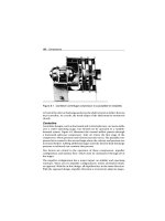
Ball
Ball valves (see Figure 9.1) are simple shutoff devices that use a ball to stop
and start the flow of fluid downstream of the valve. As the valve stem turns
to the open position, the ball rotates to a point where part or the entire hole
machined through the ball is in line with the valve-body inlet and outlet.
This allows fluid to pass through the valve. When the ball rotates so that the
hole is perpendicular to the flow path, the flow stops.
Most ball valves are quick-acting and require a 90-degree turn of the actuator
lever to fully open or close the valve. This feature, coupled with the turbulent
flow generated when the ball opening is only partially open, limits the use of
the ball valve. Use should be limited to strictly an “on-off” control function
(i.e., fully open or fully closed) because of the turbulent-flow condition and
severe friction loss when in the partially open position. They should not be
used for throttling or flow-control applications.
Ball valves used in process applications may incorporate a variety of actu-
ators to provide direct or remote control of the valve. The more common
actuators are either manual or motor-operated. Manual values have a hand-
wheel or lever attached directly or through a gearbox to the valve stem.
Control Valves 181
Thrust washer
Lever actuator
Body
Bonnet
Seat
Ball
Figure 9.1 Ball valve
The valve is opened or closed by moving the valve stem through a 90-degree
arc. Motor-controlled valves replace the handwheel with a fractional horse-
power motor that can be controlled remotely. The motor-operated valve
operates in exactly the same way as the manually operated valve.
Gate
Gate valves are used when straight-line, laminar fluid flow and minimum
restrictions are needed. These valves use a wedge-shaped sliding plate in
the valve body to stop, throttle, or permit full flow of fluids through the
valve. When the valve is wide open, the gate is completely inside the valve
bonnet. This leaves the flow passage through the valve fully open with no
flow restrictions, allowing little or no pressure drop through the valve.
Gate valves are not suitable for throttling the flow volume unless specifically
authorized for this application by the manufacturer. They generally are not
suitable because the flow of fluid through a partially open gate can cause
extensive damage to the valve.
Gate valves are classified as either rising-stem or nonrising-stem. In the
nonrising-stem valve, which is shown in Figure 9.2, the stem is threaded
into the gate. As the handwheel on the stem is rotated, the gate travels up or
down the stem on the threads, while the stem remains vertically stationary.
182 Control Valves
Closed
Figure 9.2 Nonrising-stem gate valve
This type of valve will almost always have a pointer indicator threaded onto
the upper end of the stem to indicate the position of the gate.
Valves with rising stems (see Figure 9.3) are used when it is important to
know by immediate inspection if the valve is open or closed, or when the
threads exposed to the fluid could become damaged by fluid contamina-
tion. In this valve, the stem rises out of the valve bonnet when the valve is
opened.
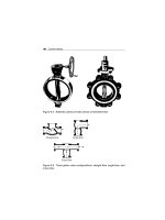
Butterfly
The butterfly valve has a disk-shaped element that rotates about a central
shaft or stem. When the valve is closed, the disk face is across the pipe and
blocks the flow. Depending upon the type of butterfly valve, the seat may
consist of a bonded resilient liner, a mechanically fastened resilient liner, an
insert-type reinforced resilient liner, or an integral metal seat with an O-ring
inserted around the edge of the disk.
As shown in Figure 9.4, both the full open and the throttled positions permit
almost unrestricted flow. Therefore, this valve does not induce turbulent
flow in the partially closed position. While the design does not permit exact
Control Valves 183
Figure 9.3 Rising stem gate valve
flow-control capabilities, a butterfly valve can be used for throttling flow
through the valve. In addition, these valves have the lowest pressure drop
of all the conventional types. For these reasons, they are commonly used in
process-control applications.
Globe
The globe valve gets its name from the shape of the valve body, although
other types of valves also may have globular-shaped bodies. Figure 9.5 shows
three configurations of this type of valve: straight-flow, angle-flow, and cross-
flow.
A disk attached to the valve stem controls flow in a globe valve. Turning
the valve stem until the disk is seated, which is illustrated in View A of
Figure 9.6, closes the valve. The edge of the disk and the seat are very
accurately machined to form a tight seal. It is important for globe valves
to be installed with the pressure against the disk face to protect the stem
packing from system pressure when the valve is shut.
While this type of valve is commonly used in the fully open or fully closed
position, it also may be used for throttling. However, since the seating
surface is a relatively large area, it is not suitable for throttling applications
where fine adjustments are required.