Industrial Machinery Repair Part 13 potx
Bạn đang xem bản rút gọn của tài liệu. Xem và tải ngay bản đầy đủ của tài liệu tại đây (413.2 KB, 35 trang )
404 Pumps
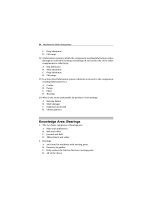
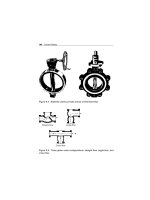
Rotating impeller
Stationary
difusser vanes
Figure 21.11 Centrifugal pump diffuser
erosion caused by liquid leaking through this tight clearance and other
causes. Eventually, the leakage could become unacceptably large and
maintenance would be required on the pump.
To minimize the cost of pump maintenance, many centrifugal pumps are
designed with wearing rings. Wearing rings are replaceable rings that are
attached to the impeller and/or the pump casing to allow a small running
clearance between the impeller and pump casing without causing wear of
the actual impeller or pump casing material.
Stuffing Box
In almost all centrifugal pumps, the rotating shaft that drives the impeller
penetrates the pressure boundary of the pump casing. It is important that
the pump is designed properly to control the amount of liquid that leaks
along the shaft at the point that the shaft penetrates the pump casing. Factors
considered when choosing a method include the pressure and temperature
of the fluid being pumped, the size of the pump, and the chemical and
physical characteristics of the fluid being pumped.
One of the simplest types of shaft seal is the stuffing box. The stuffing box
is a cylindrical space in the pump casing surrounding the shaft. Rings of
packing material are placed in this space. Packing is material in the form of
rings or strands that is placed in the stuffing box to form a seal to control
the rate of leakage along the shaft. The packing rings are held in place by
Pumps 405
a gland. The gland is, in turn, held in place by studs with adjusting nuts.
As the adjusting nuts are tightened, they move the gland in and compress
the packing. This axial compression causes the packing to expand radially,
forming a tight seal between the rotating shaft and the inside wall of the
stuffing box.
The high-speed rotation of the shaft generates a significant amount of heat as
it rubs against the packing rings. If no lubrication and cooling are provided
to the packing, the temperature of the packing increases to the point where
damage occurs to the packing, the pump shaft, and possibly the nearby
pump bearing. Stuffing boxes are normally designed to allow a small amount
of controlled leakage along the shaft to provide lubrication and cooling to
the packing. Tightening and loosening the packing gland can adjust the
leakage rate.
Lantern Ring
It is not always possible to use a standard stuffing box to seal the shaft
of a centrifugal pump. The pump suction may be under a vacuum so that
outward leakage is impossible, or the fluid may be too hot to provide ade-
quate cooling of the packing. These conditions require a modification to
the standard stuffing box.
One method of adequately cooling the packing under these conditions is to
include a lantern ring. A lantern ring is a perforated hollow ring located near
the center of the packing box that receives relatively cool, clean liquid from
either the discharge of the pump or from an external source and distributes
the liquid uniformly around the shaft toprovide lubrication and cooling. The
fluid entering the lantern ring can cool the shaft and packing, lubricate the
packing, or seal the joint between the shaft and packing against leakage of
air into the pump in the event the pump suction pressure is less than that
of the atmosphere.
Mechanical Seals
In some situations, packing material is not adequate for sealing the shaft.
One common alternative method for sealing the shaft is with mechanical
seals. Mechanical seals consist of two basic parts, a rotating element attached
to the pump shaft and a stationary element attached to the pump casing.
Each of these elements has a highly polished sealing surface. The polished
faces of the rotating and stationary elements come into contact with each
other to form a seal that prevents leakage along the shaft.
406 Pumps
Summary
The important information is summarized below.
●
Centrifugal pumps contain components with distinct purposes. The
impeller contains rotating vanes that impart a radial and rotary motion to
the liquid.
●
The volute collects the liquid discharged from the impeller at high velocity
and gradually causes a reduction in fluid velocity by increasing the flow
area, converting the velocity head to a static head.
●
A diffuser increases the efficiency of a centrifugal pump by allowing a
more gradual expansion and less turbulent area for the liquid to slow as
the flow area expands.
●
Packing material provides a seal in the area where the pump shaft
penetrates the pump casing.
●
Wearing rings are replaceable rings that are attached to the impeller and/or
the pump casing to allow a small running clearance between the impeller
and pump casing without causing wear of the actual impeller or pump
casing material.
●
The lantern ring is inserted between rings of packing in the stuffing
box to receive relatively cool, clean liquid and distribute the liquid
uniformly around the shaft to provide lubrication and cooling to the
packing.
●
There are three indications that a centrifugal pump is cavitating:
1 Noise
2 Fluctuating discharge pressure and flow
3 Fluctuating pump motor current
●
Steps that can be taken to stop pump cavitation include:
1 Increasing the pressure at the suction of the pump
2 Reducing the temperature of the liquid being pumped
3 Reducing head losses in the pump suction piping
Pumps 407
4 Reducing the flow rate through the pump
5 Reducing the speed of the pump impeller
●
Three effects of pump cavitation are:
1 Degrading pump performance
2 Excessive pump vibration
3 Damage to pump impeller, bearing, wearing rings, and seals
●
To avoid pump cavitation, the net positive suction head available must be
greater than the net positive suction head required.
●
Net positive suction head available is the difference between the pump
suction pressure and the saturation pressure for the liquid being
pumped.
●
Cavitation is the process of the formation and subsequent collapse of
vapor bubbles in a pump.
●
Gas binding of a centrifugal pump is a condition where the pump casing
is filled with gases or vapors to the point where the impeller is no longer
able to contact enough fluid to function correctly.
●
Shutoff head is the maximum head that can be developed by a centrifugal
pump operating at a set speed.
●
Pump run-out is the maximum flow that can be developed by a centrifugal
pump without damaging the pump.
●
The greater the head against which a centrifugal pump operates, the
lower the flow rate through the pump. The relationship between pump
flow rate and head is illustrated by the characteristic curve for the
pump.
●
Centrifugal pumps are protected from deadheading by providing a recir-
culation from the pump discharge back to the supply source of the
pump.
●
Centrifugal pumps are protected from run-out by placing an orifice or
throttle valve immediately downstream of the pump discharge.
408 Pumps
Positive Displacement Pumps
A positive displacement pump is one in which a definite volume of liquid is
delivered for each cycle of pump operation. This volume is constant regard-
less of the resistance to flow offered by the system the pump is in, provided
the capacity of the power unit driving the pump is not exceeded. The posi-
tive displacement pump delivers liquid in separate volumes with no delivery
in between, although a pump having several chambers may have an overlap-
ping delivery among individual chambers, which minimizes this effect. The
positive displacement pump differs from other types of pumps that deliver
a continuous even flow for any given pump speed and discharge.
Positive displacement pumps can be grouped into three basic categories
based on their design and operation: reciprocating pumps, rotary pumps,
and diaphragm pumps.
Principles of Operation
All positive displacement pumps operate on the same basic principle. This
principle can be most easily demonstrated by considering a reciprocating
positive displacement pump consisting of a single reciprocating piston in a
cylinder with a single suction port and a single discharge port, as shown in
Figure 21.12.
Reservoir Reservoir
Suction Suction
Discharge
Discharge
Discharge strokeSuction stroke
Figure 21.12 Reciprocating positive displacement pump operation
Pumps 409
During the suction stroke, the piston moves to the left, causing the check
valve in the suction line between the reservoir and the pump cylinder to
open and admit water from the reservoir. During the discharge stroke, the
piston moves to the right, seating the check valve in the suction line and
opening the check valve in the discharge line. The volume of liquid moved
by the pump in one cycle (one suction stroke and one discharge stroke) is
equal to the change in the liquid volume of the cylinder as the piston moves
from its farthest left position to its farthest right position.
Reciprocating Pumps
Reciprocating positive displacement pumps are generally categorized in
four ways: direct-acting or indirect-acting; simplex or duplex; single-acting
or double-acting; and power pumps.
Direct-Acting and Indirect-Acting
Some reciprocating pumps are powered by prime movers that also have
reciprocating motion, such as a reciprocating pump powered by a recip-
rocating steam piston. The piston rod of the steam piston may be directly
connected to the liquid piston of the pump, or it may be indirectly con-
nected with a beam or linkage. Direct-acting pumps have a plunger on
the liquid (pump) end that is directly driven by the pump rod (also the
piston rod or extension thereof ) and that carries the piston of the power
end. Indirect-acting pumps are driven by means of a beam or linkage con-
nected to and actuated by the power piston rod of a separate reciprocating
engine.
Simplex and Duplex
A simplex pump, sometimes referred to as a single pump, is a pump having
a single liquid (pump) cylinder. A duplex pump is the equivalent of two
simplex pumps placed side by side on the same foundation.
The driving of the pistons of a duplex pump is arranged in such a manner
that when one piston is on its upstroke, the other piston is on its downstroke
and vice versa. This arrangement doubles the capacity of the duplex pump
compared to a simplex pump of comparable design.
Single-Acting and Double-Acting
A single-acting pump is one that takes a suction, filling the pump cylinder on
the stroke in only one direction, called the suction stroke, and then forces
410 Pumps
Double acting
Single acting
Figure 21.13 Single-acting and double-acting pumps
the liquid out of the cylinder on the return stroke, called the discharge
stroke. A double-acting pump is one that, as it fills one end of the liquid
cylinder, is discharging liquid from the other end of the cylinder. On the
return stroke, the end of the cylinder just emptied is filled, and the end just
filled is emptied. One possible arrangement for single-acting and double-
acting pumps is shown in Figure 21.13.
Power
Power pumps convert rotary motion to low-speed reciprocating motion by
reduction gearing, a crankshaft, connecting rods, and cross heads. Plungers
or pistons are driven by the crosshead drives. The liquid ends of the low-
pressure, higher-capacity units use rod and piston construction, similar to
duplex double-acting steam pumps. The higher-pressure units are normally
single-action plungers and usually employ three (triplex) plungers. Three
or more plungers substantially reduce flow pulsations relative to simplex
and even duplex pumps.
Power pumps typically have high efficiency and are capable of develop-
ing very high pressures. Either electric motors or turbines can drive them.
They are relatively expensive pumps and can rarely be justified on the
basis of efficiency over centrifugal pumps. However, they are frequently
justified over steam reciprocating pumps where continuous duty service
is needed due to the high steam requirements of direct acting steam
pumps.
Pumps 411
In general, the effective flow rate of reciprocating pumps decreases as the
viscosity of the fluid being pumped increases, because the speed of the
pump must be reduced. In contrast to centrifugal pumps, the differential
pressure generated by reciprocating pumps is independent of fluid density.
It is dependent entirely on the amount of force exerted on the piston.
Rotary
Rotary pumps operate on the principle that a rotating vane, screw, or gear
traps the liquid in the suction side of the pump casing and forces it to the
discharge side of the casing. These pumps are essentially self-priming due
to their capability of removing air from suction lines and producing a high
suction lift. In pumps designed for systems requiring high suction lift and
self-priming features, it is essential that all clearances between rotating parts,
and between rotating and stationary parts, be kept to a minimum in order
to reduce slippage. Slippage is leakage of fluid from the discharge of the
pump back to its suction.
Due to the close clearances in rotary pumps, it is necessary to operate these
pumps at relatively low speed in order to secure reliable operation and
maintain pump capacity over an extended period of time. Otherwise, the
erosive action due to the high velocities of the liquid passing through the
narrow clearance spaces would soon cause excessive wear and increased
clearance, resulting in slippage.
There are many types of positive displacement rotary pumps, and they are
normally grouped into three basic categories: gear pumps, screw pumps,
and moving vane pumps.
Rotary Moving Vane
The rotary moving vane pump shown in Figure 21.14 is another type of
positive displacement pump used in pumping viscous fluids. The pump
consists of a cylindrically bored housing with a suction inlet on one side and
a discharge outlet on the other. A cylindrically shaped rotor, with a diameter
smaller than the cylinder, is driven about an axis place above the centerline
of the cylinder. The clearance, between rotor and cylinder at the top, is
small but increases at the bottom. The rotor carries vanes that move in and
out as it rotates to maintain sealed space between the rotor and the cylinder
wall. The vanes trap liquid on the suction side and carry it to the discharge
side, where contraction of the space expels it through the discharge line.
The vanes may swing on pivots, or they may slide in slots in the rotor.
412 Pumps
Swinging type
moving vane
Suction
Rotor
Cylinder
Discharge
Figure 21.14 Rotary moving vane pump
Screw-Type, Positive Displacement Rotary
There are many variations in the design of the screw-type positive dis-
placement rotary pump. The primary differences consist of the number of
intermeshing screws involved, the pitch of the screws, and the general direc-
tion of fluid flow. Two designs include a two-screw, low-pitch double-flow
pump, and a three-screw, high-pitch double-flow pump.
Two-Screw, Low-Pitch Screw Pump
The two-screw, low-pitch screw pump consists of two screws that mesh with
close clearances, mounted on two parallel shafts. One screw has a right-
handed thread, and the other screw has a left-handed thread. One shaft is
the driving shaft and drives the other through a set of herringbone timing
gears. The gears serve to maintain clearances between the screws as they
turn and to promote quiet operation. The screws rotate in closely fitting
duplex cylinders that have overlapping bores. All clearances are small, but
there is no actual contact between the two screws or between the screws
and the cylinder walls. The complete assembly and the usual path of flow
are shown in Figure 21.15.
Liquid is trapped at the outer end of each pair of screws. As the first space
between the screw threads rotated away from the opposite screw, a one-turn,
spiral-shaped quantity of liquid is enclosed when the end of the screw
Pumps 413
Figure 21.15 Two-screw, low-pitch screw pump
again meshes with the opposite screw. As the screw continues to rotate,
the entrapped spiral turns of liquid slide along the cylinder toward the
center discharge space while the next slug is being entrapped. Each screw
functions similarly, and each pair of screws discharges an equal quantity of
liquid in opposed streams toward the center, thus eliminating hydraulic
thrust. The removal of liquid from the suction end by the screws pro-
duces a reduction in pressure, which draws liquid through the suction
line.
Three-Screw, High-Pitch Screw Pump
The three-screw, high-pitch screw pump shown in Figure 21.16 has many
of the same elements as the two-screw, low-pitch screw pump, and their
operations are similar. Three screws, oppositely threaded on each end,
are employed. They rotate in a triple cylinder, the two outer bores of
which overlap the center bore. The pitch of the screws is much higher
than in the low-pitch screw pump; therefore, the center screw, or power
rotor, is used to drive the two outer idler rotors directly without exter-
nal timing gears. Pedestal bearings at the base support the weight of the
rotors and maintain their axial position and the liquid being pumped enters
the suction opening, flows through passages around the rotor housing,
and through the screws from each end, in opposed streams, toward the
center discharge. This eliminates unbalanced hydraulic thrust. The screw
414 Pumps
Power
Suction
Rotor
housing
Rotor
housing
Discharge
Rotor
Idler
Idler
Figure 21.16 Three-screw, high-pitch screw pump
pump is used for pumping viscous fluids, usually lubricating, hydraulic, or
fuel oil.
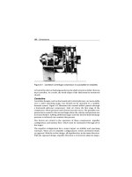
Diaphragm or Positive Displacement
Diaphragm pumps are also classified as positive displacement pumps
because the diaphragm acts as a limited displacement piston. The pump will
function when a diaphragm is forced into reciprocating motion by mechan-
ical linkage, compressed air, or fluid from a pulsating, external source.
The pump construction eliminates any contact between the liquid being
pumped and the source of energy. This eliminates the possibility of leak-
age, which is important when handling toxic or very expensive liquids.
Disadvantages include limited head and capacity range and the necessity
of check valves in the suction and discharge nozzles. An example of a
diaphragm pump is shown in Figure 21.17.
Characteristics Curve
Positive displacement pumps deliver a definite volume of liquid for each
cycle of pump operation. Therefore, the only factor that affects flow rate in
an ideal positive displacement is the speed at which it operates. The flow
resistance of the system in which the pump is operating will not affect the
flow rate through the pump. Figure 21.18 shows the characteristic curve for
a positive displacement pump.
Pumps 415
Suction
Refill
valve
Hydraulic
fluid
Reciprocating motion
Plunger
Relief
valve
Air-bleed
valve
Discharg
e
Figure 21.17 Diaphragm or positive displacement pump
Slippage
Ideal
Real
Flow rate
Pump head
Figure 21.18 Positive displacement pump characteristic curve
The dashed line in Figure 21.18 shows actual positive displacement pump
performance. This line reflects the fact that as the discharge pressure of
the pump increases, some amount of liquid will leak from the discharge of
the pump back to the pump suction, reducing the effective flow rate of the
pump. The rate at which liquid leaks from the pump discharge to its suction
is called slippage.
416 Pumps
Protection
Positive displacement pumps are normally fitted with relief valves on the
upstream side of their discharge valves to protect the pump and its dis-
charge piping from overpressurization. Positive displacement pumps will
discharge at the pressure required by the system they are supplying. The
relief valve prevents system and pump damage if the pump discharge valve
is shut during pump operation or if any other occurrence, such as a clogged
strainer, blocks system flow.
Gear Pumps
Simple Gear Pumps
There are several variations of gear pumps. The simple gear pump shown
in Figure 21.19 consists of two spur gears meshing together and revolving
in opposite directions within a casing. Only a few thousandths of an inch of
clearance exists between the case and the gear faces and teeth extremities.
Any liquid that fills the space bounded by two successive gear teeth and
the case must follow along with the teeth as they revolve. When the gear
teeth mesh with the teeth of the other gear, the space between the teeth is
reduced, and the entrapped liquid is forced out of the pump discharge pipe.
As the gears revolve and the teeth disengage, the space again opens on the
suction side of the pump, trapping new quantities of liquid and carrying it
around the pump case to the discharge. As liquid is carried away from the
suction side, a lower pressure is created, which draws liquid in through the
suction line.
Discharge
Suction
Figure 21.19 Simple gear pump
Pumps 417
With the large number of teeth usually employed on the gears, the discharge
is relatively smooth and continuous, with small quantities of liquid being
delivered to the discharge line in rapid succession. If designed with fewer
teeth, the space between the teeth is greater and the capacity increases
for a given speed; however, the tendency toward a pulsating discharge
increases. In all simple gear pumps, power is applied to the shaft of one of
the gears, which transmits power to the driven gear through their meshing
teeth.
There are no valves in the gear pump to cause friction losses as in the
reciprocating pump. The high impeller velocities, with resultant friction
losses, are not required as in the centrifugal pump. Therefore, the gear
pump is well suited for handling viscous fluids such as fuel and lubricating
oils.
Other Gear Pumps
There are two types of gears used in gear pumps in addition to the simple
spur gear. One type is the helical gear. A helix is the curve produced when
a straight line moves up or down the surface of a cylinder. The other type
is the herringbone gear. A herringbone gear is composed of two helixes
spiraling in different directions from the center of the gear. Spur, helical,
and herringbone gears are shown in Figure 21.20.
The helical gear pump has advantages over the simple spur gear. In a spur
gear, the entire length of the gear tooth engages at the same time. In a
helical gear, the point of engagement moves along the length of the gear
tooth as the gear rotates. This makes the helical gear operate with a steadier
discharge pressure and fewer pulsations than a spur gear pump.
The herringbone gear pump is also a modification of the simple gear pump.
Its principal difference in operation from the simple gear pump is that the
pointed center section of the space between two teeth begins discharging
Helical Spur Herringbone
Figure 21.20 Types of gears used in pumps
418 Pumps
Discharge
Intake
Gib
Figure 21.21 Lobe-type pump
before the divergent outer ends of the preceding space complete discharg-
ing. This overlapping tends to provide a steadier discharge pressure. The
power transmission from the driving to the driven gear is also smoother and
quieter.
Lobe-Type Pump
The lobe-type pump shown in Figure 21.21 is another variation of the sim-
ple gear pump. It is considered a simple gear pump having only two or
three teeth per rotor; otherwise, its operation or the explanation of the
function of its parts is no different. Some designs of lobe pumps are fitted
with replaceable gibs, that is, thin plates carried in grooves at the extremity
of each lobe where they make contact with the casing. The gibs promote
tightness and absorb radial wear.
Summary
The important information is summarized below.
●
The flow delivered by a centrifugal pump during one revolution of the
impeller depends upon the head against which the pump is operating.
The positive displacement pump delivers a fixed volume of fluid for each
Pumps 419
cycle of pump operation regardless of the head against which the pump
is operating.
●
Positive displacement pumps may be classified in the following ways:
1 Reciprocating piston pump
2 Gear-type rotary pump
3 Lobe-type rotary pump
4 Screw-type rotary pump
5 Moving vane pump
6 Diaphragm pump
●
As the viscosity of a liquid increases, the maximum speed at which a reci-
procating positive displacement pump can properly operate decreases.
Therefore, as viscosity increases, the maximum flow rate through the
pump decreases.
●
Slippage is the rate at which liquid leaks from the discharge of the pump
back to the pump suction.
●
Positive displacement pumps are protected from overpressurization by a
relief valve on the upstream side of the pump discharge valve.
Cavitation
Many centrifugal pumps are designed in a manner that allows the pump to
operate continuously for months or even years. These centrifugal pumps
often rely on the liquid that they are pumping to provide cooling and
lubrication to the pump bearings and other internal components of the
pump. If flow through the pump is stopped while the pump is still oper-
ating, the pump will no longer be adequately cooled, and the pump can
quickly become damaged. Pump damage can also result from pumping a
liquid that is close to saturated conditions. This phenomenon is referred
to as cavitation. Most centrifugal pumps are not designed to withstand
cavitation.
The flow area at the eye of the impeller is usually smaller than either the flow
area of the pump suction piping or the flow area through the impeller vanes.
420 Pumps
When the liquid being pumped enters the eye of a centrifugal pump, the
decrease in flow area results in an increase in flow velocity accompanied
by a decrease in pressure. The greater the pump flow rate, the greater the
pressure drop between the pump suction and the eye of the impeller. If
the pressure drop is large enough, or if the temperature is high enough,
the pressure drop may be sufficient to cause the liquid to flash to vapor
when the local pressure falls below the saturation pressure for the fluid
being pumped. Any vapor bubbles formed by the pressure drop at the eye of
the impeller are swept along the impeller vanes by the flow of the fluid. When
the bubbles enter a region where local pressure is greater than saturation
pressure farther out the impeller vane, the vapor bubbles abruptly collapse.
This process of the formation and subsequent collapse of vapor bubbles in
a pump is called cavitation.
Cavitation in a centrifugal pump has a significant effect on performance. It
degrades the performance of a pump, resulting in a degraded, fluctuating
flow rate and discharge pressure. Cavitation can also be destructive to pump
internals. The formation and collapse of the vapor bubble can create small
pits on the impeller vanes. Each individual pit is microscopic in size, but
the cumulative effect of millions of these pits formed over a period of hours
or days can literally destroy a pump impeller. Cavitation can also cause
excessive pump vibration, which could damage pump bearings, wearing
rings, and seals.
A small number of centrifugal pumps are designed to operate under con-
ditions where cavitation is unavoidable. These pumps must be specially
designed and maintained to withstand the small amount of cavitation that
occurs during their operation.
Noise is one of the indications that a centrifugal pump is cavitating. A cavitat-
ing pump can sound like a can of marbles being shaken. Other indications
that can be observed from a remote operating station are fluctuating
discharge pressure, flow rate, and pump motor current.
Recirculation
When the discharge flow of a centrifugal pump is throttled by closing the dis-
charge valve slightly, or by installing an orifice plate, the fluid flow through
the pump is altered from its original design. This reduces the fluid’s velocity
as it exits the tips of the impeller vanes; therefore, the fluid does not flow
Pumps 421
Frequency
1ϫrpm
2ϫrpm
Vane pass
(# vanesϫrpm)
Recirculation
accompanied
by some
cavitation
Velocity
Figure 21.22 Vane pass frequency
as smoothly into the volute and discharge nozzle. This causes the fluid to
impinge upon the “cutwater” and creates a vibration at a frequency equal
to the vane pass × rpm. The resulting amplitude quite often exceeds alert
set-point values, particularly when accompanied by resonance.
Random, low amplitude wide frequency vibration is often associated with
vane pass frequency, resulting in vibrations similar to cavitation and tur-
bulence, but it is usually found at lower frequencies. This can lead to
misdiagnosis. Many pump impellers show metal reduction and pitting
on the general area at the exit tips of the vanes. This has often been
misdiagnosed as cavitation.
It is very important to note that recirculation is found to happen on the
discharge side of the pump, whereas cavitation is found to happen on the
suction side of the pump.
To prevent recirculation in pumps, pumps should be operated close to their
operational rated capacity, and excessive throttling should be avoided.
When a permanent reduction in capacity is desired, the outside diameter of
the pump impeller can be reduced slightly to increase the gap between the
impeller tips and the cutwater.
Net Positive Suction Head
To avoid cavitation in centrifugal pumps, the pressure of the fluid at
all points within the pump must remain above saturation pressure.
422 Pumps
The quantity used to determine if the pressure of the liquid being pumped
is adequate to avoid cavitation is the net positive suction head (NPSH). The
net positive suction head available (NPSH
A
) is the difference between the
pressure at the suction of the pump and the saturation pressure for the liq-
uid being pumped. The net positive suction head required (NPSH
R
)isthe
minimum net positive suction head necessary to avoid cavitation.
The condition that must exist to avoid cavitation is that the net positive
suction head available must be greater than or equal to the net positive
suction head required. This requirement can be stated mathematically as
shown below.
NPSH
A
NPSH
R
A formula for NPSH
A
can be stated as the following equation:
NPSH
A
= P
suction
− P
saturation
When a centrifugal pump is taking suction from a tank or other reservoir, the
pressure at the suction of the pump is the sum of the absolute pressure at the
surface of the liquid in the tank, plus the pressure due to the elevation dif-
ference between the surface of liquid in the tank, and the pump suction less
the head losses due to friction in the suction line from the tank to the pump.
NPSH
A
= P
a
= P
st
− h
f
− P
sat
Where:
NPSH
A
= Net positive suction head available
P
a
= Absolute pressure on the surface of the liquid
P
st
= Pressure due to elevation between liquid surface and
pump suction
h
f
= Head losses in the pump suction piping
P
sat
= Saturation pressure of the liquid being pumped
Preventing Cavitation
If a centrifugal pump is cavitating, several changes in the system design or
operation may be necessary to increase the NPSH
A
above the NPSH
R
and
stop the cavitation. One method for increasing the NPSH
A
is to increase the
pressure at the suction of the pump. If a pump is taking suction from an
Pumps 423
enclosed tank, either raising the level of the liquid in the tank or increasing
the pressure in the gas space above the liquid increases suction pressure.
It is also possible to increase the NPSH
A
by decreasing the temperature of the
liquid being pumped. Decreasing the temperature of the liquid decreases
the saturation pressure, causing NPSH
A
to increase.
If the head losses in the pump suction piping can be reduced, the NPSH
A
will
be increased. Various methods for reducing head losses include increasing
the pipe diameter, reducing the number of elbows, valves, and fittings in
the pipe, and decreasing the length of the pipe.
It may also be possible to stop cavitation by reducing the NPSH
R
for the
pump. The NPSH
R
is not a constant for a given pump under all conditions,
but depends on certain factors. Typically, the NPSH
R
of a pump increases sig-
nificantly as flow rate through the pump increases. Therefore, reducing the
flow rate through a pump by throttling a discharge valve decreases NPSH
R
.
NPSH
R
is also dependent upon pump speed. The faster the impeller of a
pump rotates, the greater the NPSH
R
. Therefore, if the speed of a variable
speed centrifugal pump is reduced, the NPSH
R
of the pump decreases.
The net positive suction head required to prevent cavitation is determined
through testing by the pump manufacturer and depends upon factors
including type of impeller inlet, impeller design, pump flow rate, impeller
rotational speed, and the type of liquid being pumped. The manufacturer
typically supplies curves of NPSH
R
as a function of pump flow rate for a
particular liquid (usually water) in the vendor manual for the pump.
Troubleshooting
Design, installation, and operation are the dominant factors that affect
a pump’s mode of failure. This section identifies common failures for
centrifugal and positive-displacement pumps.
Centrifugal
Centrifugal pumps are especially sensitive to: (1) variations in liquid
condition (i.e., viscosity, specific gravity, and temperature); (2) suction vari-
ations, such as pressure and availability of a continuous volume of fluid;
and (3) variations in demand. Table 21.1 lists common failure modes for
centrifugal pumps and their causes.
424 Pumps
Table 21.1 Common failure modes of centrifugal pumps
THE PROBLEM
THE CAUSES
Insufficient discharge pressure
Intermittent operation
Insufficient capacity
No liquid delivery
High bearing temperatures
Short bearing life
Short mechanical seal life
High vibration
High noise levels
Power demand excessive
Motor trips
Elevated motor temperature
Elevated liquid temperature
Bent shaft
• • • • •
Casing distorted from excessive
pipe strain
• • • • • •
Cavitation • • •
• • • • • •
Clogged impeller •
• • • •
Driver imbalance • • •
Electrical problems (driver) • • • • • •
Entrained air (suction or seal leaks) • • • • • •
Hydraulic instability • • • • •
Impeller installed backward
(double-suction only)
• • •
Improper mechanical seal •
Inlet strainer partially clogged • • • • •
Insufficient flow through pump •
Insufficient suction pressure
(NPSH)
• • • • • •
Insufficient suction volume • • • • • • • •
Internal wear • • • •
Leakage in piping, valves, vessels • • •
Mechanical defects, worn, rusted,
defective bearings
• • •
Misalignment • • • • • •
Misalignment (pump and driver)
• • • •
Mismatched pumps in series • • • • •
Noncondensables in liquid • • • • • •
Obstructions in lines or pump
housing
• • • • • •
Pumps 425
Table 21.1 continued
THE PROBLEM
THE CAUSES
Insufficient discharge pressure
Intermittent operation
Insufficient capacity
No liquid delivery
High bearing temperatures
Short bearing life
Short mechanical seal life
High vibration
High noise levels
Power demand excessive
Motor trips
Elevated motor temperature
Elevated liquid temperature
Rotor imbalance • • •
Specific gravity too high • • •
Speed too high • •
Speed too low • • • •
Total system head higher than
design
• • • • • • • •
Total system head lower than
design
• • • • • •
Unsuitable pumps in parallel
operation
• • • • • • • •
Viscosity too high • • • •
Wrong rotation • • • •
Source: Integrated Systems Inc.
Mechanical failures may occur for a number of reasons. Some are induced
by cavitation, hydraulic instability, or other system-related problems. Others
are the direct result of improper maintenance. Maintenance-related prob-
lems include improper lubrication, misalignment, imbalance, seal leakage,
and a variety of others that periodically affect machine reliability.
Cavitation
Cavitation in a centrifugal pump, which has a significant, negative effect
on performance, is the most common failure mode. Cavitation not only
degrades a pump’s performance, but also greatly accelerates the wear rate
of its internal components.
426 Pumps
Causes
There are three causes of cavitation in centrifugal pumps: change of phase,
entrained air or gas, and turbulent flow.
Change of Phase
The formation or collapse of vapor bubbles in either the suction piping
or inside the pump is one cause of cavitation. This failure mode normally
occurs in applications such as boiler feed, where the incoming liquid is at
a temperature near its saturation point. In this situation, a slight change
in suction pressure can cause the liquid to flash into its gaseous state. In
the boiler-feed example, the water flashes into steam. The reverse process
also can occur. A slight increase in suction pressure can force the entrained
vapor to change phase to a liquid.
Cavitation due to phase change seriously damages the pump’s internal com-
ponents. Visual evidence of operation with phase-change cavitation is an
impeller surface finish like an orange peel. Prolonged operation causes small
pits or holes on both the impeller shroud and vanes.
Entrained Air/Gas
Pumps are designed to handle gas-free liquids. If a centrifugal pump’s
suction supply contains any appreciable quantity of gas, the pump will
cavitate. In the example of cavitation due to entrainment, the liquid
is reasonably stable, unlike with the change of phase described in the
preceding section. Nevertheless, the entrained gas has a negative effect
on pump performance. While this form of cavitation does not seriously
affect the pump’s internal components, it severely restricts its output and
efficiency.
The primary causes of cavitation due to entrained gas include: two-phase
suction supply, inadequate available net positive suction head (NPSH
A
), and
leakage in the suction-supply system. In some applications, the incoming
liquid may contain moderate to high concentrations of air or gas. This may
result from aeration or mixing of the liquid prior to reaching the pump or
inadequate liquid levels in the supply reservoir. Regardless of the reason,
the pump is forced to handle two-phase flow, which was not intended in its
design.
Turbulent Flow
The effects of turbulent flow (not a true form of cavitation) on pump perfor-
mance are almost identical to those described for entrained air or gas in the
Pumps 427
preceding section. Pumps are not designed to handle incoming liquids that
do not have stable, laminar flow patterns. Therefore, if the flow is unstable,
or turbulent, the symptoms are the same as for cavitation.
Symptoms
Noise (e.g., like a can of marbles being shaken) is one indication that a cen-
trifugal pump is cavitating. Other indications are fluctuations of the pressure
gauges, flow rate, and motor current, as well as changes in the vibration
profile.
How to Eliminate
Several design or operational changes may be necessary to stop centrifugal-
pump cavitation. Increasing the available net positive suction head (NPSH
A
)
above that required (NPSH
R
) is one way to stop it. The NPSH required to
prevent cavitation is determined through testing by the pump manufacturer.
It depends upon several factors, including: type of impeller inlet, impeller
design, impeller rotational speed, pump flow rate, and the type of liquid
being pumped. The manufacturer typically supplies curves of NPSH
R
as a
function of flow rate for a particular liquid (usually water) in the pump’s
manual.
One way to increase the NPSH
A
is to increase the pump’s suction pressure.
If a pump is fed from an enclosed tank, either raising the level of the liquid
in the tank or increasing the pressure in the gas space above the liquid can
increase suction pressure.
It also is possible to increase the NPSH
A
by decreasing the temperature of
the liquid being pumped. This decreases the saturation pressure, which
increases NPSH
A
.
If the head losses in the suction piping can be reduced, the NPSH
A
will be
increased. Methods for reducing head losses include: increasing the pipe
diameter; reducing the number of elbows, valves, and fittings in the pipe;
and decreasing the pipe length.
It also may be possible to stop cavitation by reducing the pump’s NPSH
R
,
which is not a constant for a given pump under all conditions. Typically, the
NPSH
R
increases significantly as the pump’s flow rate increases. Therefore,
reducing the flow rate by throttling a discharge valve decreases NPSH
R
.
In addition to flow rate, NPSH
R
depends on pump speed. The faster the
pump’s impeller rotates, the greater the NPSH
R
. Therefore, if the speed of
428 Pumps
a variable-speed centrifugal pump is reduced, the NPSH
R
of the pump is
decreased.
Variations in Total System Head
Centrifugal-pump performance follows its hydraulic curve (i.e., head versus
flow rate). Therefore, any variation in the total backpressure of the system
causes a change in the pump’s flow or output. Because pumps are designed
to operate at their Best Efficiency Point (BEP), they become more and more
unstable as they are forced to operate at any other point because of changes
in total system pressure, or head (TSH). This instability has a direct impact
on centrifugal-pump performance, reliability, operating costs, and required
maintenance.
Symptoms of Changed Conditions
The symptoms of failure due to variations in TSH include changes in motor
speed and flow rate.
Motor Speed
The brake horsepower of the motor that drives a pump is load dependent.
As the pump’s operating point deviates from BEP, the amount of horsepower
required also changes. This causes a change in the pump’s rotating speed,
which either increases or decreases depending on the amount of work that
the pump must perform.
Flow Rate
The volume of liquid delivered by the pump varies with changes in TSH. An
increase in the total system back-pressure results in decreased flow, while a
back-pressure reduction increases the pump’s output.
Correcting Problems
The best solution to problems caused by TSH variations is to prevent the vari-
ations. While it is not possible to completely eliminate them, the operating
practices for centrifugal pumps should limit operation to an acceptable
range of system demand for flow and pressure. If system demand exceeds
the pump’s capabilities, it may be necessary to change the pump, the system
requirements, or both. In many applications, the pump is either too small
or too large. In these instances, it is necessary to replace the pump with one
that is properly sized.
For the application where the TSH is too low and the pump is operating in
run-out condition (i.e., maximum flow and minimum discharge pressure),