AERATION: Principles and Practice ( VOLUME 11 ) - Chapter 5 doc
Bạn đang xem bản rút gọn của tài liệu. Xem và tải ngay bản đầy đủ của tài liệu tại đây (5.04 MB, 42 trang )
© 2002 by CRC Press LLC
Surface and
Mechanical Aeration
5.1 INTRODUCTION
Mechanical aeration is defined in this text as the transfer of oxygen to water by
mechanical devices so as to cause entrainment of atmospheric oxygen into the bulk
liquid by surface agitation and mixing. In addition, equipment that causes dispersion
or aspiration of compressed air, high purity oxygen, or atmospheric air by the shearing
and pumping of a rotating turbine or propeller will also be included. One may classify
mechanical aeration devices based on the physical configuration of the equipment
and its operation. Classifications that will be used in this text include low speed
surface aerators, motor speed (high speed), axial surface aerators, horizontal rotors,
submerged, sparged turbine aerators and aspirating aerators. Detailed descriptions,
applications, and performance ranges for these devices will be provided below.
It appears that mechanical aeration in wastewater was introduced to overcome
problems with diffuser clogging in activated sludge systems. The concept was
introduced in Europe in the late 1910s, predominantly in the UK, and spread to the
U.S. slowly. By 1929, mechanical aeration plants outnumbered diffused aeration
plants in the UK by two to one. In the U.S., a survey by Roe (1938) indicated that
about 100 activated sludge plants employed mechanical aeration, 200 were using
diffused aeration, and approximately 20 had combined aeration systems.
Porous tile diffuser clogging in Sheffield, England spurred the development of
an Archimedian screw-type aerator in 1916. In 1920, Sheffield built a full-scale
facility using submerged horizontal paddle wheels in narrow channels [1.2 to 1.8 m]
(4 to 6 ft) that were about 1.2 m (4 ft) deep, called the Haworth System. Located
midway between the channel ends that interconnected each aeration tank, the shaft
rotated at 15 to 16 rpm producing a longitudinal velocity of (0.53 m/s) 1.75 ft/sec.
The movement of wastewater along the channel created a wave action that allowed
transport of oxygen from atmospheric air to the water. The power consumed was
reported to be 0.114 kwh/m
3
(576 hp-h/million gallons). The use of pumps to replace
the paddles in moving wastewater along the channels did not provide sufficient
oxygen transfer and were supplemented by submerged paddles to satisfy oxygen
demand. Triangular paddles, which replaced the rectangular paddles in 1948,
improved performance by 40 to 50 percent when the shaft was operated at twice
the original rotational speed.
The Hartley aeration system was similar to that used at Sheffield but employed
propellers fixed to inclined shafts. These units were located at the U-shaped ends
of the shallow interconnected channels. A series of diagonal baffles were located at
intervals along the channels. They were set at an angle in the direction of flow to
reduce the velocity, prevent suspended solids separation, and create new liquid
5
© 2002 by CRC Press LLC
surfaces to come in contact with the atmosphere. These systems were used at
Birmingham and Stoke-on-Trent in the UK. Neither the Haworth nor the Hartley
system found service in the U.S.
Other horizontal shaft systems were also being developed in these early years.
In 1929, pilot studies at Des Plaines, IL were described in which an aeration device
employing a steel latticework was attached to a horizontal shaft to form a paddle-
wheel. The paddlewheel, with a diameter of 66 to 76 cm (26 to 30 in), was suspended
along the entire length of the aeration tank and was partially submerged so that when
rotated, it would agitate the liquid surface. A vertical baffle, running along the entire
basin length 46 cm (18 in) from the wall and located below the paddlewheel,
terminated at the surface with a narrow trough located at right angles to the basin
wall. The shaft was rotated in the range of 36 to 60 rpm by an electric motor. This
rotation toward the wall caused mixed liquor to rise upward between the baffle and
wall and fall downward in the main basin. The wave-like motion at the surface
created new liquid surfaces to contact the air. Mixed liquor flowed in a spiral roll
configuration down the aeration tank. This system was known as the Link-Belt
aerator. Link-Belt aerators were installed in several U.S. plants in the 1930s but
were not in production by the late 1940s.
Another horizontal rotor device often referred to as a brush aerator was developed
in the U.S. and Europe in the 1930s. Called brush aerators because of the use of
street cleaning brushes during early development, these devices were usually fastened
to one longitudinal wall of the aeration tank and partially submerged below the
liquid surface. Rotating at speeds ranging from 43 to 84 rpm, the brushes created a
wave-like motion across the liquid surface and induced a spiral roll to the wastewater
as it flowed down the aeration tank. Kessner employed brushes as well as a combina-
tion of brushes and submerged paddles in Holland as early as 1928. Similar in design
and function as the brush aerators described above, Kessner employed the submerged
paddles mounted on a horizontal shaft that rotated at 3 to 7 rpm. These paddles
supplemented the brush and provided a reinforced spiral roll to the mixed liquor.
The newer Kessner brushes employed acute triangles cut from stainless steel sheet
in place of the brush. The aeration tank bottom was either rounded, or the sidewalls
sloped near the bottom to enhance circulation.
An interesting modification of the horizontal paddle aeration system resulted in
the combination of paddlewheels and diffused air developed in Germany and
reported by Imhoff in 1926. The submerged paddles, made of steel angles and
mounted on horizontal shafts running longitudinally along the aeration basin, were
rotated counter to the upward flow of bubbles. Diffused air was provided longitu-
dinally along the wall or center-line of the tank. More recent applications of this
principle may be found in Chapter 3.
In addition to the horizontal rotor concept, vertical draft tube aerators were also
being developed at this time. In the early 1920s the Simplex system was marketed
in the UK. The Simplex system in its earliest version employed at Bury, England
was a vertical draft tube device placed in a relatively deep hopper-bottom tank. A
vertical steel draft tube with open bottom located about 15 cm (6 in) from the floor
was suspended at the tank center. At the top of the tube was a cone with steel vanes.
The cone was rotated at about 60 rpm drawing mixed liquor up through the draft
© 2002 by CRC Press LLC
tube. The wastewater was then sprayed outward over the surface of the tank. Each
draft tube was driven by its own motor through a speed reducer or by a line shaft
with individual clutches. A number of vertical draft tube systems resembling the
Simplex aerator became popular in the U.S. in the 1930s and 1940s. They were the
predominant mechanical aerators in the U.S. by the 1950s. Their general character-
istics are tabulated in Table 5.1.
The performance of these early mechanical aeration systems was reported as
wire power required per unit mass of BOD
5
removed (kWh/lb BOD
5
). Results of
test conducted in the U.S. by Roe (1938) are given in Table 5.2. Note that a rough
estimate of the AE in lb O
2
transferred/kWh can be calculated from these power
values by assuming that the ultimate BOD is 1.4x BOD
5
and that no nitrification is
taking place. These estimated values are presented in Table 5.2. Note that the values
are not at standard conditions but are estimated in wastewater at field temperature
and basin DO (not given).
In the 1950s and 1960s, many low-speed aerators were sold in the U.S. and they
apparently performed satisfactorily. However, there was no generally accepted
method of evaluating the units, and the main testing efforts were aimed at process
performance. A major flaw soon became apparent relative to aerator maintenance
and reliability, the gear reducers. Often gear reducers failed within a short period
of time after initial start-up. Some lasted for a year or two, but many failed after
only a few weeks or months.
TABLE 5.1
Characteristics of Vertical Draft Tube Aerators in 1950
Manufacturer Characteristic Construction
Number of
Aerator
Sizes Variable Control
American Well
Works
Down-draft by propeller at bottom of tube,
aspirator orifice plate at top, radial inlet
troughs
Time switch;
adjustable orifice
plate openings
Chicago Pump
Company
Up-draft, propeller driven flow discharge
against diffuser cone at top
10 propeller
sizes
Time switch
Infilco, Inc. Up-draft, induced by horizontal, radially
vaned impeller at top
Time switch;
adjustable
impeller height
Vogt Mfg.
Company
Down-draft produced by impeller in tube,
radial inlet troughs
Walker Process
Equipment, Inc.
Down-draft by propeller at bottom of tube,
aspirator orifice plate at top, radial troughs
Time switch;
adjustable orifice
plate openings
Yeomans
Brothers
Company
Up-draft induced by spiral vaned revolving
cone at top
4 sizes of
aerators
Time switch;
optional variable
speed
From Committee on Sewage and Industrial Waste Practice (1952).
Air Diffusion in Sewage Works- MOP
5,
Federation of Sewage and Industrial Waste Associations, Champaign, IL.
© 2002 by CRC Press LLC
From a performance perspective, the 1950s vintage impellers were almost all
simple radial flow devices. A number of impeller designs were imported from Europe
and adopted by U.S. suppliers. Innovative blade designs were developed as well by
U.S. manufacturers. At that time and into the 1960s, no reliable test procedure was
available to assess the value of these designs. The effects of impeller speed, basin
geometry, and other important dependent variables were either unknown or poorly
understood. As a result, it is likely that most systems were under designed. On the
TABLE 5.2
Power Consumption by Early Mechanical Aeration Plants
City
Make of
Device
Wastewater
Flow
(MGD)
BOD
5
Reduction
(mg/l)
Wire Power
Consumed
(kWh/lbBOD
5
removed)
Estimated AE
based on
wire power
(lb O
2
/kWh)
Buhl, MN Yeomans 0.36 182
*
0.205 1.58
Geneva, IL Yeomans 0.7 116 0.210 1.54
Batavia, IL American 0.611 178 0.220 1.47
Mitchell, SD Yeomans 0.5 188 0.275 1.18
Woodstock, IL Yeomans 0.733 100
*
0.312 1.04
Chelsea, MI American 0.15 156
*
0.323 1.00
Waverly, IA American 0.42 177
*
0.407 0.80
Libertyville, IL American 0.106 223 0.452 0.72
Christopher, IL Yeomans 0.38 73
*
0.480 0.68
Elmhurst, IL Chicago 2.00 85 0.495 0.65
Princeton, IL Yeomans 0.488 67
*
0.498 0.65
Collingswood, NJ Link-Belt 0.5 294 0.547 0.59
Flora, IL Chicago 0.16 205 0.589 0.55
Rochelle, IL American 0.326 206 0.61 0.53
Harlem, NY — 0.500 95 0.627 0.52
Dane Co. Asylum, WI — 0.042 275 0.651 0.50
Clintonville, WI American 0.305 97 0.674 0.48
Holland/Kessner
**
Kessner brush Domestic Domestic 0.13–0.19 2.49–1.71
Holland/Kessner
**
Kessner brush Industrial Industrial 0.25–0.52 1.30–0.62
Muskegon, MI
†
Combined
#
1.37 131 0.348 0.93
Mansfield, OH
†
Combined
#
3.5 94 0.425 0.76
Escabana, MI
†
Combined
#
0.75 135 0.447 0.72
Phoenix, AZ
†
Combined
#
11.25 128 0.447 0.72
Jackson, MI
†
Combined
#
7.5 87 0.785 0.41
Note:
MGD
×
0.44 = m
3
/s, kWh/lb
×
2.205 = kWh/kg, lb/kWh
×
0.453 = kg/kWh.
*
Estimated;
**
After Kessner (in
Air Diffusion in Sewage Works
, 1952).
†
From C. E. Keefer, (1940);
#
Combined-diffused air and mechanical aeration,
‡
estimated assuming
BOD
u
= 1.4 BOD
5
and no nitrification; nonstandard conditions; based on wire power.
From Committee on Sewage and Industrial Waste Practice (1952).
Air Diffusion in Sewage Works- MOP
5,
Federation of Sewage and Industrial Waste Associations, Champaign, IL.
© 2002 by CRC Press LLC
other hand, virtually all worked to the satisfaction of the operators with the exception
of mechanical problems.
By the mid 1970s, the mechanical problems had been recognized and at least
to a certain extent, addressed by the major aerator suppliers. The dynamics of the
market were changing at that time, with the old-line equipment suppliers being
squeezed by newer entrants. Since the 1960s Lightnin, a major manufacturer of
mixers, made a big push in the low-speed aerator market using a very inexpensive
impeller (a four-blade pitched blade turbine). Shortly thereafter, Philadelphia Gear’s
Mixing Division entered the market using specially designed reducers and new
impellers that were less prone to cause failures. From a mechanical perspective,
these new suppliers represented the best level of quality ever seen in the business
at a cost that the older manufacturers found hard to match. At least as important,
these mixing companies were very familiar with the best approach to blending liquids
and suspending solids, and by the mid 1980s, the leading low-speed aerator manu-
facturers in the U.S. were Lightnin and Philadelphia Mixers. That situation still
exists as we enter the twenty-first century since no new low-speed aerator suppliers
have come into the market in the last 30 years.
Today, the low-speed surface aerator remains a very popular device in certain
niches. High-purity oxygen suppliers have found that good low-speed aerators do the
best job for their process, and Eimco continues to be successful in their Carrousel™
ditch process using the low-speed vertical shaft machines. In addition, many low-speed
units are performing well in activated sludge systems.
For lagoon applications and situations where capital cost is a major factor,
several manufacturers began to offer motor speed or high-speed aerators in the
1970s. Primarily of a floating configuration, the development aimed at lagoons and
small-extended aeration facilities. All used marine propellers as the impeller of the
nonsnagging type. In the early days of development, these devices were plagued
by mechanical difficulties largely due to motor bearing failures as well as poor
manufacturing quality control. The hydraulic forces were the main cause of bearing
failure, and it took a while for manufacturers to find effective designs to ensure
long-term service. New styles of motor speed devices are currently being designed
and marketed. Because of their popularity, innovation continues to improve per-
formance and reliability.
At the same time the low-speed aerator was being improved in the 1960s, the
horizontal rotor became popular in oxidation ditch applications in the U.S. and
Europe. A number of different rotor designs have been used, ranging from brushes
to the more complex discs. Their efficiency is consistent with the radial flow style
of low-speed aerator impellers, and similar concerns regarding mechanical integrity
(gear reducer and bearings) have been addressed and largely overcome.
Also designed for lagoon applications, aspirating devices became popular in the
U.S. in the 1970s. A number of different configurations have been used including a
floating device that uses a marine propeller mounted at a shallow angle to the
horizontal and a submersible pump unit using a vertical draft tube. Fashioned in a
way that allows air to be aspirated through its hollow shaft, these devices are effective
mixers, adding some oxygen in the process. These units have also experienced a
series of historical mechanical difficulties, mainly associated with shaft-supported
© 2002 by CRC Press LLC
bearings located below the water surface. A number of approaches have been used
in an effort to resolve these problems. The problems remain, and although very
inexpensive, they do not provide top performance or trouble free operation.
Finally, in this brief historical overview, are the submerged, sparged turbine
aerators that have been used for decades in a number of forms. Industrial mixing
requirements often have called for the introduction of a gas into a liquid. The major
mixing companies in the U.S. (Lightnin, Philadelphia Mixers, and Chemineer) were
all familiar with the concept. In the 1960s and 1970s, several companies tried to
improve the surface aerator performance by designing aerators that would disperse
compressed air using what is essentially a mechanical mixer. Two general types
were developed at that time: the radial and draft tube (radial) and an open-style axial
flow type (down-pumping impeller above the sparger). These units were plagued
with mechanical problems and did not perform as well as anticipated. As a result,
they have fallen out of favor in today’s market. The draft tube turbine aerator is
similar in concept in that it uses a down-pumping impeller positioned above an air-
release device. The impeller and sparger are located within a draft tube that assists
flow direction and shearing action. These devices, used in deep basins (7.6 to 9.75
m) (25 to 32 ft), have experienced some early mechanical failures that have recently
been overcome. A radial flow submerged turbine aerator uses a radial flow impeller
positioned above a sparger. Offered in the early 1960s and still used today in aerobic
digestion applications, its mechanical reliability is high.
This chapter will elaborate on mechanical aeration systems, their characteristics,
applications, performance, design, and operation.
5.2 LOW-SPEED SURFACE AERATORS
5.2.1 D
ESCRIPTION
Low-speed mechanical aerators have an impeller positioned at the water surface and
pull liquid directly upward in a vertical direction from beneath them. The liquid is
then accelerated by the impeller vanes and discharged in essentially a horizontal
direction at the impeller rim. The high-speed (supercritical) liquid plume at dis-
charge, in contrast to the slow moving liquid in the tank (subcritical), results in a
transition from supercritical to subcritical flow producing a hydraulic jump. The
large interfacial area that is generated results in oxygen transfer. The gas phase may
be considered continuous, and the liquid phase discontinuous. The reservoir of
oxygen is infinite. Therefore, oxygen transfer is limited only by the rate at which
the impeller can expose new liquid interfaces to the atmosphere. A relatively large
quantity of liquid must be pumped in this process for two reasons: to maintain a
high driving force of oxygen in the entraining liquid and to distribute the oxygen
enriched liquid throughout the basin. Low speed aerators have extremely high
pumping capacities.
The low-speed aerator typically uses impellers configured to pump liquid in a
radial manner, so it is generally thought of as a radial flow device. There are,
however, a number of impeller configurations (Figures 5.1 to 5.3). Some impellers
are flat discs with rectangular or slightly curved vanes attached to the periphery of
© 2002 by CRC Press LLC
the disc lower surface. Others use inverted conical bodies with vertical blades
originating at the center that may be located at top, bottom, or both sides of the
cone. New designs include variations of pitched blade turbines, curved blade discs
and reverse curvature discs. Most, if not all, surface aerators are hydraulically
dependent on liquid level over the impeller (submergence). A small change in liquid
level will generally cause a significant change in the head requirements of the
impeller. This affects both power input and oxygen transfer. Many impeller con-
figurations will have their own characteristic submergence-aeration efficiency-
pumping rate curves. In some instances, a small change in submergence may result
in as much as ±50 percent in power variation, whereas with the less sensitive
impellers the variation may only be ±10 percent.
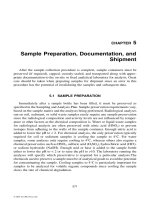
FIGURE 5.1
Low-speed surface aerator (courtesy of US Filter–Envirex, Waukesha, WI).
© 2002 by CRC Press LLC
Low-speed aerators typically operate at speeds in the range of 20 to 100 rpm.
Thus, a gearbox is employed to reduce impeller speed below that of the motor. As
described above, the early designs suffered from gear reducer failures. The problem
was found to be associated with the reducers that were specified by the manufac-
turers. They had purchased gear reducers from the large U.S. gear manufacturers
and had requested normal industrial reducers. The design of such machines was
simply inadequate to handle the large hydraulic loads imposed by aerator duty, so
the weakest link would fail. Usually, that was the bearings supporting the impeller
shaft, but occasionally, the gears themselves would crater. The result was expensive,
time-consuming, and, generally, a universal problem.
Different aerator suppliers dealt with the problem in different ways. Yeomans,
for example, added a large bearing at the impeller (and, therefore, right near the
water) to take the large loads. All suppliers increased the size of the reducers by
increasing the service factor. (The service factor is defined as the calculated power
FIGURE 5.2
Low-speed surface aerators. [A) Courtesy of Baker Hughes, Houston, TX;
B) courtesy of Philadelphia Mixers Corp., Palmyra, PA.]
© 2002 by CRC Press LLC
transmission rating of the reducer divided by the actual amount of power used.) By
using large reducers with service factors of 2.5 to 3.0, the manufacturers were able
to reduce failures to a manageable level. At that point, failures began to occur at the
impeller shaft, and so, the shafts were beefed up again reducing failure rates.
More progressive ways of reducing failures were adopted by some suppliers.
For example, Lightnin introduced a new reducer design that was developed with
Falk for heavy-duty mixer applications—the “hollow quill.” That design protects
the gears and bearings from the effects of hydraulic forces. A different approach
was adopted by Infilco, who joined forces with Philadelphia Gear. They conducted
field stress tests to quantify the magnitude of the hydraulic forces and tailored the
right reducer to the application.
Low-speed surface aerators are typically bridge mounted because of their size
and weight, but they can be float mounted where necessary. The shaft and impeller
are suspended from the drive unit above. Platform or bridge designs must account
for torque and vibration and should be designed for at least four times the maximum
anticipated moment (torque and impeller side load). Some aerators will be equipped
with submerged draft tubes to provide better flow distribution within the basin. They
are typically used in deep basins (greater than 4.6 m [15 ft]) where the aerator alone
may not provide sufficient dispersion of oxygen throughout the basin. The draft tube
may also serve as a surge control device preventing wave generation in the tank and
FIGURE 5.2 (continued)
© 2002 by CRC Press LLC
eliminating the pulsing loads on the gear-motor assembly. As an alternative to the
draft tube, an auxiliary submerged impeller may be installed on the extended impeller
shaft. The submerged impeller will increase the amount of liquid pumped from the
bottom of the basin thereby increasing oxygen dispersion. The location and config-
uration of the turbine will depend on basin geometry and the use of multiple units.
Typically, radial flow impellers are used, but axial flow devices are also employed
in practice. It should be noted that the additional impeller will result in greater power
draw. The unsupported shaft will create high side loads that will create greater stress
on the gearbox and must be considered in the design. Unsupported shaft lengths up
to about 9 m (30 ft) have been used, but above that, supported shafts and bottom
bearings are recommended.
Surface aeration devices create mists that can lead to freezing problems in the
northern parts of the world. Furthermore, mists may generate odor problems and
have been of concern in air-borne disease transmission. Mist shrouds are mounted
above the impeller to restrict the flight of sprays and to reduce the accumulation of
ice on the underside of the platform. A drive-ring hood may also be employed for
ice control. Splashing effects can also be minimized with proper geometric design
FIGURE 5.3
Low-speed surface aerator (courtesy of Geiger, Karlsruhe, Germany).
© 2002 by CRC Press LLC
of the aeration tank. Heat loss induced by surface aerators is of concern in winter
months and should be estimated in the design of the biological treatment system.
5.2.2 A
PPLICATIONS
The low-speed aeration systems are simple in design, easy to install, relatively easy
to maintain with no submerged parts, and require little operational control. Units
are available with motor power ranging from several kilowatts to over 150 kW. The
low-speed surface aerators for the Carrousel ™ (oxidation ditch) process range from
4 to 150 kW. The very high pumping capacity of low-speed surface aerators allows
them to provide excellent mixing and solids suspension in large volumes. It is
important to note, however, that using only a surface impeller without a draft tube
limits effective mixing depths. The units are flexible in turndown capacity, providing
capability for 30 to 50 percent turndown with liquid level sensitive impellers.
Typically, though, turndown in transfer rate and power consumption cannot be done
independently of pumping capacity and mixing. Thus, oxygen uptake rates can limit
the system design when dealing with high strength wastes in a high-rate system.
Under variable flow and organic load conditions, the oxygen transfer rate for these
units is controlled by the use of variable or dual-speed motors, variable frequency
drives, or liquid-level sensitive impellers in conjunction with adjustable weirs.
Low-speed aerators were initially used in completely mixed aeration tanks of
conventional and high-rate systems for design flows under about 0.6 m/s (13 mgd).
Later, they were used in low-rate extended aeration facilities. Today, they are found in
a number of different activated sludge configurations over a wide design flow capacity
including tanks-in-series, oxidation ditches, and high-purity oxygen processes.
5.2.3 P
ERFORMANCE
R
ANGE
The performance of low-speed surface aerators depends on a number of variables
including impeller submergence, power input per unit basin volume, aerator pump-
age, basin geometry, number and spacing of units, use of baffles, draft tubes and
auxiliary impellers, temperature, and wastewater characteristics. Because of the
complex hydraulic-pneumatic phenomena involved, it is not realistic to scale-up
performance data from small shop tests or models. In general, small units have
higher oxygen transfer rates per unit power than very large units. However, the
volume of liquid under aeration for any given aerator, has an influence on the oxygen
transfer rate, i.e., the smaller the liquid volume per unit of aerator pumpage (power
consumption), the higher the transfer rate. Wastewater will affect the oxygen transfer
rate as measured by alpha. Values of alpha depend on aerator type, power, basin
configuration, and submergence as well as wastewater. Typical values of alpha are
reported to range from 0.3 to 1.1 (Boyle et al., 1989; Stenstrom and Gilbert, 1981;
WPCF, 1988) and are not very reliable. Few well-designed field studies have been
performed with mechanical aeration equipment owing to sampling and measurement
difficulties with these systems (See Chapter 7). A discussion of alpha will be found
later in this chapter.
© 2002 by CRC Press LLC
Today, performance of low-speed surface aerators are normally reported as
standard aeration efficiencies (SAE) expressed as mass oxygen transferred per unit
wire power per time (kg/kWh) under standard conditions of temperature, pressure,
and DO concentration. Note that power may be measured as drawn wire power or
as delivered shaft power (e.g., motor wire-power
×
motor efficiency
×
drive efficiency
= delivered shaft power). In this chapter, power will be reported as wire power
(hp or kW). In the U.S. and Europe, the standard test conditions are clean water
(alpha = 1.0), T= 20°C, barometric pressure = 101.3 kP
a
(1.0 atm) and 0.0 dissolved
oxygen (see Table 2.2).
The old radial flow impellers were found to perform in the range of 1.6 to
1.9 kg/kWh (2.6 to 3.1 lb/hp-h) in clean water at standard conditions. Today, good
suppliers can now deliver performance in the range of 1.9 to 2.2 kg/kWh (3.1 to
3.7 lb/hp-h) under typical basin configuration/power situations.
5.3 HIGH-SPEED OR MOTOR SPEED AERATORS
5.3.1 D
ESCRIPTION
These axial-flow, vertical axis aerators usually have a propeller-type impeller driven
by a motor without a gearbox, a shroud in which the impeller is located, and a flow-
directing casing. Liquid is drawn upward through the volute. The design of the casing
determines the direction of the liquid jets that discharge from the unit. The flow may
be horizontal from the aerator, upward and away from the aerator, or downward and
away from the unit. These liquid jets partially break into droplets, then entrain and
disperse atmospheric air into bubbles on impingement into the bulk liquid of the tank.
A large interfacial area is created that promotes oxygen transfer. The impellers
typically used are smaller than those used for low-speed surface machines and have
lower pumping capacity for a given motor size. Flow patterns are similar to the low-
speed units, but bulk liquid rotation within the tank is virtually absent.
The high-speed aerators were initially designed using marine impellers of the
nonsnagging type (Figure 5.4). In the 1980s, new styles of high-speed impellers
were developed. One, using an Archimedes screw-style impeller, was developed in
Europe and trademarked “screwpeller” (Figure 5.5). Another uses a high efficiency
“scooped” impeller (Figure 5.6). These impellers provide higher water pumpage
rates than the marine propellers and produce reduced hydraulic loads to the unit
because of their smoother operation.
Because there is no gear reducer, the impeller rotates at the same speed as the
motor. Speeds range from as high as 1800 rpm for the smaller units to about 900 rpm
for the large aerators. Motor sizes range from 0.75 to 112 kW (1 to 150 hp). Because
of the elimination of the gearbox, the high-speed aerator is lighter than the low-
speed unit. Since they are lighter and have a limited shaft length, they are better
suited for float mounting and are seldom fixed mounted. Floats are typically poly-
urethane foam covered with a stainless steel jacket. In order to improve the effective-
ness of the small impellers, a draft tube may be employed to extend the depth of
influence. On the other hand, in shallow lagoon applications, an anti-erosion plate
© 2002 by CRC Press LLC
FIGURE 5.4
High-speed surface aerator (courtesy of Aqua-Aerobics Systems, Inc., Rockford, IL).
FIGURE 5.5
High-speed surface aerator (courtesy of Aquaturbo Systems, Inc., Springdale, AR).
© 2002 by CRC Press LLC
may be attached to the bottom of the intake cone resulting in inflow from the sides
of the cone rather than from below.
Like their low-speed counterparts, mists are formed from the discharge liquid
jets. One solution may be the use of low-trajectory jets. A plate or ring is installed
above the diffuser assembly so as to extend the diameter of the diffuser resulting in
a flat spray. Some manufacturers may also provide a dome above the diffuser that
directs flow downward into the tank. These devices will not only reduce mist but
will also reduce heat loss from the discharging sprays. At least one manufacturer
produces an electrical anti-icing device that eliminates ice formation on the diffuser
head and motor.
5.3.2 A
PPLICATIONS
The high-speed surface aerator was developed primarily for lagoon applications.
Presently, they are also found in some activated sludge facilities. Their low cost,
portability, and flexibility are important marketing issues. On the other hand, they
suffer from poor mixing characteristics and possess no turndown capability. As
discussed later, the use of these devices in lagoons is promoted insofar as mixing is
not as critical as for the high biomass activated sludge systems, and most lagoons are
considered as facultative and partially mixed systems. In fact, floating mixer/aerators
may be selected to improve overall lagoon performance by providing low-power mixing
in situations where turndown is an important issue. When oxygen demand is low, some
aerators may be shut down without impairing mixing, which can be provided by low
power consuming submersible mixer/aerators. Most high-speed devices will produce
greater cooling than a comparable low-speed machine. As described below, the marine
propellers are not as efficient oxygen transfer devices as the low-speed impellers.
The high-speed aerator is also used in aerobic digesters. Unfortunately, mixing
requirements often control design, and high-speed devices will often produce an
FIGURE 5.6
High-speed surface aerator (courtesy of Aeration Industries International, Inc.,
Minneapolis, MN).
© 2002 by CRC Press LLC
over-aerated condition. The best equipment for this application includes jet aerators,
submerged turbines, and combination aerator/mixers.
5.3.3 P
ERFORMANCE
R
ANGE
The performance of high-speed aerators depends on basin configuration, unit spac-
ing, power input per unit volume, pumpage rate, use of baffles, draft tubes or anti-
erosion plates, impeller type, temperature, and wastewater characteristics among
others. As with low-speed devices, performance scale-up from small test tanks is
not advisable. The smaller the tank volume per unit pumping rate, the higher the
transfer rate. Wastewater affects oxygen transfer in a manner similar to low-rate
systems. Values of alpha are reported to fall in the same range as the low speed
devices but the database is unreliable.
The high-speed axial propeller units typically produce standard aeration efficien-
cies in the range of 1.1 to 1.4 kg/kWh (1.8 to 2.3 lb/hp-h). The newer impeller
designs claim values about 10 percent higher than the propellers.
5.4 HORIZONTAL ROTORS
5.4.1 D
ESCRIPTION
Horizontal rotor aerators were introduced early in the 20
th
century. Initially, they were
used in rectangular tanks and placed along a longitudinal sidewall (see Section 5.1).
More recently, the horizontal rotors are found in oxidation ditch applications. The
earlier Kessner brushes had a horizontal cylinder rotor with bristles submerged in
the wastewater at approximately the one-half diameter. Now, most devices use angle
steel, other steel flat or curvilinear blades, plastic bars or blades, or plastic discs
instead of the earlier bristles.
In the ditch configurations, the rotor spans the width of the channel and rotates
so as to discharge a water jet or spray upstream and downward, while imparting a
velocity to the liquid as the rotor blades rise out of the water. Oxygen is transferred
at the air-water interfaces of the water droplets, or jets, as they are thrown outward
from the blades or disc surfaces. Simultaneously, the liquid is propelled by the rotor,
thereby mixing the basin and imparting a velocity to the bulk liquid along the basin
length downstream. The velocity imparted by the rotor ranges from 0.3 to 1.0 m/s
(1 to 3 ft/s) depending on rotor size and speed. Typical rotor lengths range from
3 to 9 m (10 to 30 ft) and are normally used in channels with liquid depths up to
about 4 m (13 ft). The rotor is driven by a motor equipped with a gear reducer that
provides a rotor speed ranging from 40 to over 80 rpm. A V-belt drive transfers
power from the motor to the gear reducer. Speed changes may be provided by sheave
changes at the V-belt or by staged bevel/spur gear reducers. The end of the rotor is
independently supported by special heavy duty bearing systems that compensate for
linear expansion and misalignments.
As described above, the rotor may be equipped with a number of different blade
configurations. The steel bladed rotors are typically 69 to 107 cm (27 to 42 in) in
diameter (Figure 5.7) and may be submerged 4 to 30 cm (1.6 to 12 in) depending
© 2002 by CRC Press LLC
upon rotor diameter and power requirement. The disc aerators are wafer-thin circular
plates (typically about 1.5 m [5 ft] in diameter) and submerged in the water for
approximately one-eighth to three eighths of their diameter (Figure 5.8). Recesses or
nodules located along the disc surface are used in some devices to provide additional
lift of the entrained water into the air increasing oxygen transfer and mixing.
The power required to drive the rotor may be controlled by several processes.
Standard aeration efficiency (SAE) is also controlled by these methods. These
methods include rotor speed (RPM) and submergence of rotor blades, for all devices.
For the disc units, power and SAE are also affected by the number of discs on the
shaft and the reversal of disc rotation when nodules are employed on the disc surface.
Daily variation in oxygen demand is most often met by changing wastewater depth
(submergence) by variable weir adjustments. Baffles are often located downstream
of the rotors to direct flow downward and to produce greater liquid turbulence. This
process normally results in higher SAEs for a given power level.
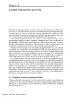
FIGURE 5.7
Horizontal rotor aerator (courtesy of Lakeside Equipment Corp., Bartlett, IL).
© 2002 by CRC Press LLC
The operation of horizontal rotors is accompanied by liquid splash and mist. In
cold climates, this effect may cause significant operational problems with ice build-up.
Splash plates are often provided to protect the drive mechanism. Plastic and fiberglass
covers and heated hoods are also available.
5.4.2 A
PPLICATIONS
Today, horizontal rotor aerators are used almost entirely to aerate oxidation ditches,
although some units have been used in lagoon applications. The rotors are available
in a range of blade configurations and lengths up to 9 m (30 ft). Motor drives are
available in the range of 2 to 90 kW providing speeds of 40 to over 70 rpm. Problems
associated with gear reducer and bearing reliability have been addressed and largely
overcome today. The unidirectional discharge of the rotor is ideal for inducing
circulation in a channel type system. Multiple units are often used along the ditch
length to promote proper oxygenation and circulation. The disc-type rotors also offer
the flexibility of adding or removing discs from the shaft to tune the rotor system
to the aeration requirements of the process. Rotor aeration systems are capable of
FIGURE 5.8
Horizontal rotor aerator (courtesy of US Filter–Envirex, Waukesha, WI).
© 2002 by CRC Press LLC
performing over a range of power inputs by several control strategies described
above, thereby providing significant turndown capacity. Maintenance requirements
are low and operational reliability is reported to be excellent.
5.4.3 P
ERFORMANCE
R
ANGE
The efficiency of horizontal rotors depends on blade (disc) submergence, rotor
speed, blade numbers and configuration, liquid temperature, and wastewater char-
acteristics. The rotors perform in the same range as the radial flow style of low
speed aerators. The range of SAE for horizontal rotors is 1.5 to 2.1 kg/kWh (2.5 to
3.5 lb/hp-h). Lesser submergence will decrease the oxygen transfer rate and power,
but the SAE will remain approximately the same. One manufacturer claims that
the range of oxygen transfer rate (SOTR) is in excess of six to one when both rotor
speed and submergence are changed. Yet, SAE values remain relatively constant.
As with other mechanical aeration devices, the value of alpha for rotor systems is
not well documented.
5.5 SUBMERGED TURBINE AERATORS
5.5.1 D
ESCRIPTION
Submerged turbine aerators have been used for decades in a number of forms. The
submerged turbine normally consists of an open-bladed turbine mounted on a vertical
shaft driven by a gear motor assembly, with an air sparger located under the turbine.
Both radial flow and axial flow configurations have been employed.
The open-style axial flow turbines use down-pumping impellers. They were
designed primarily for basin depths ranging from 4.5 to 6.0 m (15 to 20 ft). Major
mechanical difficulties have been encountered with this device caused primarily by
the extremely high unbalanced hydraulic forces. The fluid forces acting on the long,
overhung shaft and the critical speed considerations both dictate a low operating
speed, and thus, a speed reducer. The rotational speed of the impeller is typically
in the range of 50 to 100 rpm. Poor oxygen transfer was also obtained with these
systems. As a result, these devices have fallen out of favor and are rarely seen today
in wastewater treatment applications.
In an effort to improve performance, the down-pumping axial impeller (flat blade
or airfoil) was placed within a draft tube along with the sparge ring (Figure 5.9).
This change appears to assist flow direction and allows for high shearing action.
These units are typically used in basins 7.6 to 9.8 m (25 to 32 ft) deep and achieve
higher transfer efficiencies. The sparge ring is typically located at a mid-depth of
3.0 to 4.6 m (10 to 15 ft) depth, which allows for deep tank aeration at conventional
depth blower pressures. Shaft lengths are smaller than the open-style units and
the unit may be operated at higher speeds (130–180 rpm) and lower torque. As a
result, smaller, less costly drive assemblies are required. Initially plagued by
mechanical difficulties owing to the severe hydraulic forces, these problems have
been overcome today.
© 2002 by CRC Press LLC
The radial flow submerged turbine uses a radial (horizontal) flow impeller
positioned above the sparge ring. Several impellers are typically placed on the same
shaft above the lower impeller. This was the typical industrial configuration and has
been offered since the 1960s. It is less efficient than the axial units and finds limited
application as an aeration device.
For all of these devices, oxygen transfer is affected by the high turbulence field
provided by the impeller at the air bubble column discharging from the sparger. The
high-energy field breaks up the bubbles and disperses them into the bulk liquid.
Therefore, the mechanism of transfer is different than that of the surface aerators
described above in that the fluid becomes the continuous phase, and the gas is the
discontinuous phase. Oxygen supply is controlled by the rate of airflow to the system.
Transfer rate depends on both airflow and the oxygen stripping efficiency of the
impeller. Power is the sum of both the shaft input power to the turbine and the power
to deliver the gas. Flow patterns are determined by three major components that
FIGURE 5.9
Draft tube aerator (courtesy of Philadelphia Mixers Corp., Palmyra, PA).
© 2002 by CRC Press LLC
include the vertical circulation provided by the impeller(s), the rotating water mass
moving in the direction of impeller rotation, and the geometric effects of the basin
and baffles.
Typically, all of these devices are driven by a standard direct connected gear-
motor drive. Both motor and drive are mounted on a beam that spans the aeration
tank. The shaft with impellers is bearing supported in the gear-reducing drive head.
Shaft alignment is assured by a steady bearing.
5.5.2 A
PPLICATIONS
The submerged turbine aerators are best suited to deep tank applications. The draft
tube turbines are also found in some oxidation ditches such as the barrier ditch
process. The radial flow submerged turbine is used largely in aerobic digesters where
independent mixing and oxygen transfer are desired. The submerged turbines offer
high pumping capacity and the ability to independently control mixing and aeration
by adjusting turbine speed and airflow rate. Further, these units eliminate spray-
related ice and mist formation caused by the surface aeration units. This factor also
minimizes heat loss observed for the surface units. The disadvantages of these
devices include higher capital costs and the need for blower and submerged piping.
As discussed above, the open style axial turbine and radial flow submerged turbine
exhibit lower performance than that found with other surface aeration and submerged
aeration systems. The draft tube turbine appears to be more competitive from the
point of view of aeration efficiency. Available submerged turbine aerators match
common motor sizes up to 112 kW (150 hp). Special designs include motors up to
and exceeding 260 kW (349 hp). Airflow rates vary from 0.2 to greater than
8.0 m
3
/min (8 to 300 scfm).
5.5.3 P
ERFORMANCE
R
ANGE
The performance of submerged turbines depends on turbine configuration, basin
geometry, airflow rate, turbine speed, temperature, and wastewater characteristics.
The open-style axial submerged turbine has been reported to provide values of SAE
in the range of 1.0 to 1.6 kg/kWh (1.75 to 2.75 lb/hp-h), whereas the radial flow
turbines provide SAEs in the range of 1.1 to 1.5 kg/kWh (1.8 to 2.5 lb/hp-h). The
improved draft tube turbine has been shown to provide substantially higher SAEs
of 1.6 to 2.4 kg/kWh (2.7 to 4.0 lb/hp-h). However, in barrier ditch applications,
these draft tube turbines produced low SAE values ranging from 0.8 to 1.2 kg/kWh
(1.4 to 2.0 lb/hp-h) (Boyle et al., 1989).
5.6 ASPIRATING AERATORS
5.6.1 D
ESCRIPTION
Aspirating devices draw atmospheric air into a mixing chamber where wastewater
is contacted with the air. The air-water mixture is subsequently discharged into the
aeration basin.
© 2002 by CRC Press LLC
At least two types of configurations are employed. The first uses a tube mounted
at an angle in the water with a motor and air intake above the water surface. A
propeller located below the water surface within the tube draws liquid down through
the tube creating a low-pressure zone at the hub of the propeller. This low pressure
draws air through the air inlet to the propeller hub where it intermixes with the water.
Turbulence breaks up the air bubbles and the resultant air-water mixture discharges
into the basin mixing the contents and dispersing the oxygen (Figure 5.10). These
units may be mounted on booms or floats and can be mounted at various angles
depending on basin geometry and aeration and mixing requirements. The degree of
mixing, direction of flow, and speed of aspiration can be controlled.
Another aspirating device uses a submersible pump supplemented with a vertical
air intake tube open to the atmosphere. The pumping of the liquid creates a low-
pressure region at the impeller thereby drawing air down the shaft. Air and water
are combined and discharge through diffuser channels into the aeration basin
(Figure 5.11). Turbulence and flow created by the impeller break up the air bubbles
and mix the basin. These units may be mounted on the basin floor, placed on
removable guide rails, or fixed to a floating support.
5.6.2 A
PPLICATION
These devices are good, low-cost mixers but are not efficient aeration devices. They
may be supplemented with small blowers to force more air into the unit, improving
oxygen transfer rate but not efficiency. They are well suited for lagoon systems where
supplemental mixing may be desirable for achieving more operational flexibility. The
submersible pumping action may provide directional flow to move wastewater and/or
FIGURE 5.10A
Selected aspirator aerators (courtesy of Aeromix Systems, Inc., Minneapolis,
MN).
A
FIGURE 5.10B
(Courtesy of Aeration Industries International, Inc., Minneapolis, MN.)
B
© 2002 by CRC Press LLC
© 2002 by CRC Press LLC
sludge to aerated zones. Furthermore, the units may be used during low oxygen
demand periods to supply mixing and to allow cycling of other lagoon aerators
(on and off) to meet system oxygen demand without sacrificing mixing. They also
find applications aerobic digesters, post and preaeration systems, flow equalization
tanks, for mixing stratified lakes, for ice control in harbors and as temporary supple-
mental aeration in wastewater treatment plants. The tube angle mounted units are
available in sizes ranging from 0.75 to 75 kW (1 to 100 hp). The submersible units
can be found in sizes ranging from 1.5 to 75 kW (2 to 100 hp).
5.6.3 P
ERFORMANCE
R
ANGE
The aspirating aerator demonstrates low aerator efficiency (SAE), ranging from 0.4
to 0.9 kg/kWh (0.6 to 1.5 lb/hp-h). As described above, they are good low-cost
mixers that are most effective in supplementing other aeration equipment and pro-
viding additional mixing energy to the system.
5.7 FACTORS AFFECTING PERFORMANCE
5.7.1 G
ENERAL
Two important relationships for agitated basins with a single-phase liquid are those
for the dimensionless power number,
P
0
, and Reynolds Number,
R
e
,
(5.1)
(5.2)
where,
P
= the mixer power input
D
= the impeller diameter
N
= the impeller speed
ρ
= liquid density
µ
= absolute viscosity
FIGURE 5.10C
(Courtesy of Aeromix Systems, Inc., Minneapolis, MN.)
PPND
0
35
=
ρ
RDN
e
=
2
ρµ
© 2002 by CRC Press LLC
FIGURE 5.11
Selected aspirator aerators. [A) Courtesy of JetTech, Edwardsville, KS; B)
and C) courtesy of Nopon Oy, Helsinki, Finland; D) courtesy of Aeration Industries Interna-
tional, Inc., Minneapolis, MN.]
© 2002 by CRC Press LLC
FIGURE 5.11 (continued)
C