Kinetics of Materials - R. Balluff S. Allen W. Carter (Wiley 2005) WW Part 9 ppt
Bạn đang xem bản rút gọn của tài liệu. Xem và tải ngay bản đầy đủ của tài liệu tại đây (3.36 MB, 40 trang )
13.3:
CONSERVATIVE MOTION
305
interface. On the other hand, nonconservative motion occurs when the motion
of the interface is coupled to long-range diffusional fluxes of one or more of the
components of the system.
Conservative motion can be achieved under steady-state conditions only when
the atomic fraction of each component is the same in the adjoining crystals (see
Exercise
13.1).
For sharp interfaces, atoms are simply transferred locally across
the interface from one adjoining crystal to the other and there is no need for the
long-range diffusion of any species to the boundary. This local transfer can occur
by the simple shuffling of atoms across the interface and/or by the creation of
crystal defects (vacancies or interstitials) in one grain which then diffuse across
the boundary and are destroyed in the adjoining grain, thus transferring atoms
across the interface.* Examples of conservative motion are the glissile motion of
martensitic interfaces (see Chapter
24)
and the thermally activated motion of grain
boundaries during grain growth in a polycrystalline material.
During
nonconservative interface motion,
the boundary must act
as
a source
for the fluxes.
To
accomplish this for sharp interfaces, atoms must be added to, or
removed from, one or both of the the crystals adjoining the interface. This generally
causes crystal growth or shrinkage of one or both of the adjoining crystals and hence
interface motion with respect to one or both of the crystals. This can occur by the
creation at the interface of the point defects necessary to support the long-range
diffusional fluxes of substitutional atoms or by atom shuffling to accommodate the
addition or removal of interstitial atoms. Nonconservative interface motion and the
role of interfaces as sources or sinks for diffusional fluxes are of central importance in
a wide range of phenomena in materials. For example, during diffusional creep and
sintering of polycrystalline materials (Chapter
16),
and the thermal equilibration
of point defects, atoms diffuse to grain boundaries acting as point-defect sources.
In these cases, the fluxes require the creation or destruction of lattice sites at the
boundaries. In
multicomponent-multiphase
materials, the growth or shrinkage of
the phases adjoining heterophase interfaces often occurs via the long-range diffusion
of components in the system. In such cases, heterophase interfaces again act as
sources for the diffusing components.
Further aspects of the conservative and nonconservative motion of sharp inter-
faces are presented below. The mechanism for the motion of a diffuse interface is
discussed in Section
13.3.4.
13.3 CONSERVATIVE MOTION
13.3.1
Sharp boundaries of several different types can move conservatively by the glide
of interfacial dislocations. In many cases, this type of motion occurs over wide
ranges of temperature, including low temperatures where little thermal activation
is available.
Glissile Motion of Sharp Interfaces
by
Interfacial Dislocation Glide
Small-Angle Grain Boundaries.
As described in Appendix
B,
these semicoherent
boundaries are composed
of
arrays of discretely spaced lattice dislocations. For
2Shuffles are small displacements of atoms (usually smaller than an atomic spacing) in
a
local
region, such as the displacements that occur in the core of
a
gliding dislocation.
306
CHAPTER
13:
MOTION
OF
CRYSTALLINE INTERFACES
certain small-angle boundaries, these dislocations can glide forward simultaneously,
allowing the boundary to move without changing its structure. The simplest ex-
ample is the motion
of
a symmetric tilt boundary by the simultaneous glide of its
edge dislocations as in Fig. 13.1. An important aspect of this type of motion is the
change in the macroscopic shape of the bicrystal specimen which occurs because
the transfer of atoms across the boundary from grain 2 to grain
1
by shuffling is a
highly correlated process. Each atom in the shrinking grain is moved to a prede-
termined position in the growing grain as it is overrun by the displacement field of
the moving dislocation array and shuffled across the boundary. The positions of all
the atoms in the bicrystal are therefore correlated with the position of the interface
and there is a change in the corresponding macroscopic shape of the specimen as
the boundary moves. This type of interface motion has been termed
military
to
distinguish
it
from the disorganized
civilian
type of interface motion that occurs
when an incoherent general interface moves as described in Section 13.3.3 [3]. In
the latter case, there is no change in specimen shape.
Numerous experimental observations of the glissile motion
of
small-angle bound-
aries have been made
[2].
Most general small-angle boundaries possess more than
one family of dislocations having different Burgers vectors. Glissile motion of such
boundaries without change
of
structure is possible only when the glide planes of
all the dislocation segments in the array lie on a common zone with its axis out
of the boundary plane. When this is not the case, the boundary can move conser-
vatively only by the combined glide and climb of the dislocations as described in
Section 13.3.2.
Large-Angle Grain Boundaries.
Semicoherent large-angle grain boundaries contain-
ing localized line defects with both dislocation and ledge character can often move
forward by means of the lateral glissile motion of their line defects. A classic ex-
ample is the motion of the interface bounding a
(111)
mechanical twin in the f.c.c.
structure illustrated in Fig. 13.2. This boundary can be regarded alternatively as
a large-angle grain boundary having a misorientation corresponding to a 60" rota-
tion around a
[lll]
axis. The twin plane is parallel to the
(111)
matrix plane, and
the twin (i.e., island grain) adopts a lenticular shape in order to reduce its elastic
energy (discussed in Section 19.1.3). The macroscopically curved upper and lower
sections of the interface contain arrays
of
line defects that have both dislocation and
ledge character, as seen in the enlarged view in Fig. 13.2b. Note that the interface
is semicoherent with respect to a reference structure (see Section B.6) taken to be
a bicrystal containing a flat twin boundary parallel to
(111).
The line defects are
glissile in the
(111)
plane and their lateral glissile motion across the interface in
the directions of the arrows causes the upper and lower sections of the interface to
move normal to themselves in directions that expand the thickness of the lenticu-
lar twin. In essence, the gliding line defects provide special sites where atoms can
be transferred locally across the interface relatively easily by a military shuffling
process, making the entire boundary glissile. This type of glissile interface motion
produces a macroscopic shape change of the specimen for the same geometric rea-
sons that led to the shape changes illustrated in Fig. 13.1. When a line defect with
Burgers vector
b'
passes a point on the interface, the material is sheared parallel to
the interface by the amount
b.
At the same time, the interface advances by
h,
the
height of the ledge associated with the line defect. These effects, in combination,
produce the shape change. A pressure urging the interface sections to move to
13.3
CONSERVATIVE
MOTION
307
fY
IX
Matrix
Twin
/
Matrix
/
Figure
13.2:
(a)
A
lenticular twin in an
f.c.c.
structure bounded by
glissile
interfaces
containing dislocations
possessing
ledge
character
viewed
along
[TlO].
(b)
An
enlarged
view
of
the dislocation-step
region.
The interface
is
semicoherent with respect to
a
reference
structure. corresponding to the bicrystal formed by
a
60”
rotation around
[lll].
The Burgers
vector
of
the dislocation
is
a
translation vector
of
the DSC-lattice
of
the
reference
bicrystal.
which
is
the fine grid shown
in
the
figure
(see
Section B.6).
(c)
The same atomic
structure
as
in
(b).
The
interface
now
is
considered to be coherent with respect
to
a
reference
structure.
corresponding to the
f.c.c.
matrix
crystal. In this
framework.
the dislocation
is
regarded
as
a
coherency dislocation
(see
Section B.6).
(d)
The shape change produced by formation
of
a
twin
across
the entire specimen
cross
section.
expand the twin and produce this shape change can be generated by applying the
shear stress,
oxy,
shown in Fig. 13.2~. The magnitude of this pressure is readily
found through use of
Eq.
12.1.
The force (per unit length) tending to glide the line
defects laterally is given by
Eq.
11.1,
f
=
baxy.
The work done by the applied
force in moving
a
unit area of the boundary
a
distance
6s
is then
(bxlh) boxy,
and
the pressure
is
therefore
(13.2)
This type of glissile boundary motion occurs during mechanical twinning when
twins form in matrix grains under the influence of applied shear stresses
[4].
The
glissile lateral motion of the line defects can be very rapid, approaching the speed
of sound (see Section 11.3.1), and the large number of line defects that must be
generated on successive
(111)
planes can be obtained in
a
number of ways, including
a
dislocation “pole” mechanism. Glissile motion of other types of large-angle grain
boundaries by the same basic mechanism have been observed
[2].
Heterophase Interfaces.
In certain cases, sharp heterophase interfaces are able to
move in military fashion by the glissile motion of line defects possessing dislocation
character. Interfaces of this type occur in martensitic displacive transformations,
which are described in Chapter 24. The interface between the parent phase and
the newly formed martensitic phase is
a
semicoherent interface that has no long-
range stress field. The array of interfacial dislocations can move in glissile fashion
and shuffle atoms across the interface. This advancing interface will transform
308
CHAPTER
13:
MOTION
OF
CRYSTALLINE INTERFACES
the parent phase to the martensite phase in military fashion and
so
produce a
macroscopic shape change.
13.3.2
Thermally Activated Motion of Sharp Interfaces by Glide and Climb
of Interfacial Dislocations
The motion of many interfaces requires the combined glide and climb of interfacial
dislocations. However, this can take place only at elevated temperatures where
sufficient thermal activation for climb is available.
Small-Angle Grain Boundaries.
As mentioned, a small-angle grain boundary can
move in purely glissile fashion if the glide planes of all the segments in its dislocation
structure lie on a zone that has its axis out
of
the boundary plane. However, this will
not usually be the case, and the boundary motion then requires both dislocation
glide and climb. Figure
13.3
illustrates such an interface, consisting of an array
of two types
of
edge dislocations with their Burgers vectors lying at
45"
to the
boundary plane, subjected to the shear stress
oZy.
Equation
11.1
shows that the shear stress exerts a pure climb force
f
=
bnZy
on
each dislocation, which therefore tends to climb in response to this force. However,
mutual forces between the dislocations in the array will tend to keep them at the
regular spacing corresponding
to the boundary structure
of
minimum energy. All
dislocations will then move steadily along
+z
by means of combined glide and climb.
The boundary as a whole will therefore move without changing its structure, and
its motion will produce a specimen shape change, the same as that produced by the
glissile motion of the boundary in Fig.
13.1.
Successive dislocations in the array
must execute alternating positive and negative climb, which can be accomplished
by establishing the diffusion currents of atoms between them
as
shown in Fig.
13.3.
Each current may be regarded as crossing the boundary from the shrinking crystal
to the growing crystal.
An approximate model for the rate of boundary motion can be developed if it is
assumed that the rate of dislocation climb is diffusion limited
[2].
Neglecting any
effects of the dislocation motion and the local stress fields of the dislocations on
Figure
13.3:
Thermally activated conservative motion of a small-angle symmetric tilt
boundary containing two arrays of edge dislocations with orthogonal Burgers vectors.
f
is
the force exerted on each dislocation, by the applied stress. Arrows indicate atom fluxes
between dislocations.
13.3.
CONSERVATIVE
MOTION
309
the diffusion] a flux equation for the atoms can be obtained by combining Eqs.
3.71
(13.3)
Under diffusion-limited conditions, the vacancies can be assumed to be maintained
at
equilibrium
at
the dislocations. The dislocations act as ideal sources (Sec-
tion
11.4.1)
and, therefore] at the dislocations
pv
=
0.
When an atom is inserted at
a dislocation
of
type
2
acting as a sink (Fig.
13.3),
the dislocation will move forward
along
x
by the distance
fi
R/b.
The force on it acting in that direction is
axyb/fi,
and the work performed by the stress is therefore
(fi
R/b)(oxyb/fi)
=
oxy
R.
The
boundary value for the diffusion potential
@A
at the cores of these dislocations is,
therefore,
+:(sink)
=
pi
-
oxy
R
(13.4)
where
pi
is the chemical potential of atoms in stress-free material. Similarly, at
dislocations of type
1,
acting as sources, @(source)
=
pi
+
gzy
R.
The average potential gradient in the region between adjacent dislocations is
then
(V@A)
=
2R
ozy/d,
where
d
is the dislocation spacing. The approximate area
per unit length,
A,
through which the diffusion flux passes is of order
A
E
d.
Using
these quantities and Eq.
13.3,
and assuming that the variations in *D due to local
variations in the vacancy concentration are small enough to be neglected, the total
atom current per unit length entering a dislocation
of
type
2
is given by
(13.5)
where
*D
is the self-diffusivity as measured under equilibrium conditions. The
volume of atoms causing climb (per unit length per unit time) is then
IAR,
and the
corresponding climb rate is therefore
vc
=
IAR/b.
Each dislocation moves along
z
by combined climb and glide at a rate that exceeds its climb rate by
fi,
and the
boundary velocity is then
v
=
five,
or
4fi
R*D
bfkT
gxy
V=
(13.6)
Since
d
=
b/(Ofi)
[7]
and the pressure on the boundary is P
=
tbzyl
Eq.
13.6
may
be expressed
(13.7)
Equation
13.7
shows that the velocity is proportional to the pressure through a
boundary mobility,
MBl
itself proportional to the self-diffusivity, *D. The activa-
tion energy for boundary motion will therefore be that for crystal self-diffusion as
expected for a crystal diffusion-limited process.
Large-Angle Grain Boundaries.
Semicoherent large-angle boundaries may move con-
servatively through the lateral motion of their dislocations (which also generally
possess ledge character) by means of combined glide and climb. In these bound-
aries, the coherent patches of the boundary between the dislocations are relatively
3Equation
13.3
was first obtained
by
Herring and
is
useful in modeling
the
kinetics of diffusional
creep
[5]
and sintering
[6]
in pure metals.
310
CHAPTER
13:
MOTION OF CRYSTALLINE INTERFACES
stable and therefore resistant to any type of motion. The dislocations, however, are
special places in the boundary that support the transfer of atoms across the inter-
face from the shrinking to the growing crystal relatively easily as the dislocations
glide and climb.
The example in Fig. 13.4 is an extension of the model for the motion of
a small-
angle boundary by the glide and climb of interfacial dislocations (Fig. 13.3). Fig-
ure 13.4 presents an expanded view of the internal “surfaces” of the two crystals
that face each other across a large-angle grain boundary. Crystal dislocations have
I
V
Figure
13.4:
Expanded view of the “internal surfaces”
of
two crystals facing each other
across
a
grain boundary. Lattice dislocations
AB
and
DE
have impinged upon the boundary,
creating line defects with
both
ledge and dislocation character which may glide and climb in
the boundary in the directions of the arrows creating growth or dissolution spirals.
impinged upon the boundary from crystals
1
and
2,
causing the formation of extrin-
sic dislocation segments in the boundary along
CB and
EF,
re~pectively.~ These
extrinsic segments have Burgers vector components perpendicular to the boundary
plane and possess ledge character. Crystal
1
can grow and crystal
2
can shrink if
the segments
CB
and
EF
climb and glide in the directions of the arrows under the
influence of the pressure driving the boundary. This can be achieved by the diffu-
sion of atoms across the boundary from segment
EF
to segment
CB,
thus allowing
the boundary to move conservatively. The continued motion of the segments in
these directions will cause them to wrap themselves up into spirals around their
pole dislocations in the grains (i.e.,
AB
and ED). The dislocations will therefore
form crystal growth or dissolution spirals in the boundary similar to the growth spi-
rals that form on crystal free surfaces
at
points where lattice dislocations impinge
on the surface (see Fig. 12.5). There is therefore a close similarity between this
mode of dislocation-induced boundary motion and the motion of free surfaces due
to the action of growth
or
dissolution ledge spirals as discussed in Section
12.2.2.
Probable observed examples of such dislocation growth or dissolution spirals on
grain boundaries are shown in Fig. 13.5.
The rates of boundary motion will depend strongly upon the available densities of
boundary dislocations with ledge character. The formation of such dislocations by
4See Section
B.7
for
a
discussion
of
extrinsic
vs.
intrinsic interfacial dislocations.
13
3
CONSERVATIVE MOTION
311
Figure
13.5:
grain boundaries.
From
Gleiter
181
and Dingley and Pond
191.
Observed examples
of
apparent dislocation growth or dissolution spirals on
the homogeneous nucleation of dislocation loops in the boundary is highly unlikely
at the pressures that are usually exerted on boundaries
[2].
An important source
may then be impinged lattice dislocations, as described above. However, under
many conditions, the rate of this type of boundary motion may be very slow.
13.3.3
Shuffling
at
Pure Ledges.
Interfaces capable of supporting pure ledges (see Sec-
tion
B.7)
may migrate by the transverse motion of the ledges across their faces
much like the motion of free surfaces described in Section
12.2.2.
However, the
ledges in interfaces can move conservatively by the shuffling of single atoms or small
groups
of
atoms from the shrinking crystal to the growing crystal at kinks in the
interface ledges. This type of motion does not produce
a
specimen shape change.
Its conservative nature is in contrast to the nonconservative nature of free-surface
motion via surface-ledge migration. The shuffles will be thermally activated, and
a
simple analysis shows that the interface velocity can then be written
Thermally Activated Motion of Sharp Interfaces by Atom Shuffling
(13.8)
where
NI,
is the number of kink sites per unit interface area,
N,
is the average
number of atoms transferred per shuffle,
vo
is
a
frequency. and Ss and
ES
are the
activation entropy and energy for the shuffling.
As
in Eq.
13.7,
the velocity is
proportional to the driving pressure,
P,
through a boundary mobility,
MB.
This
mobility is critically dependent upon the density of kink sites, which may vary
widely for different interfaces. Ledges will be present initially in vicinal interfaces,
312
CHAPTER
13:
MOTION
OF
CRYSTALLINE INTERFACES
but these will tend to be grown off during the interface motion and can therefore
support only a limited amount of motion. Ledges cannot be nucleated homoge-
neously in the form
of
small pillboxes at significant rates at the driving pressures
usually encountered. However, heterogeneous nucleation could be of assistance in
certain cases. In general, widely different boundary mobilities may be expected
under different circumstances
[2].
Uncorrelated Shuffling at General Interfaces.
Interfaces that are general with respect
to all degrees of freedom possess irregular structures and cannot support localized
line defects of any significant strength. However, in many places along an irregular
general interface, the structure can be perturbed relatively easily to allow atoms to
be shuffled from the shrinking crystal to the growing crystal by means of thermal
activation. In this case, a simple analysis of the interface velocity leads again to a
relationship of the form of Eq.
13.8
[2].
However, the quantity
Nk
appearing in the
mobility
MB
is now the density of sites in the interface at which successful shuffles
can occur. Under most circumstances, the intrinsic density of these sites will be
considerably larger than the density of kink sites on vicinal stepped boundaries,
and the mobility of general interfaces will be correspondingly larger.
13.3.4
Diffuse interfaces of certain types can move by means of self-diffusion. One example
is the motion of diffuse antiphase boundaries which separate two ordered regions
arranged on different sublattices (see Fig. 18.7). Self-diffusion in ordered alloys
allows the different types of atoms in the system to jump from one sublattice to the
other in order to change the degree of local order as the interface advances. This
mechanism is presented in Chapter 18.
Thermally Activated Motion of Diffuse Interfaces
by
Self-Diffusion
13.3.5
The conservative motion of interfaces can be severely impeded by a variety of mech-
anisms, including solute-atom drag, pinning by embedded particles, and pinning at
grooves that form at the intersections of the interfaces with free surfaces. We take
up the first two of these mechanisms below and defer discussion of surface grooving
and pinning at surface grooves to Section 14.1.2 and Exercise 14.3.
Impediments to Conservative Interface Motion
Solute-Atom Drag.
Solute atoms, which are present either by design or as un-
wanted impurities, often segregate to interfaces where they build up “atmospheres”
or segregates. This effect is similar in many respects to the buildup of solute-atom
atmospheres at dislocations (discussed in Section
3.5.2).
For the interface to move,
it must either drag the solute atmosphere along with it or tear itself away. The
dragging process requires that the solute atoms diffuse along with the moving in-
terface under the influence of the attractive interaction forces exerted on them by
the interface. In many cases, the forced diffusive motion of the solute atmosphere
will be slow compared to the rate at which the interface would move in the absence
of the solute atoms. The solute atoms then exert a
solute-atom drag force
on the
moving interface and impede its motion. In cases where the applied pressure mov-
ing the interface
is
sufficiently large, the interface will be torn away from the solute
atmosphere.
A
number of models for solute-atom drag, involving various simpli-
13
3
CONSERVATIVE
MOTION
313
fications, have been developed
[2].
Figure
13.6
shows some of the main behavior
predicted by Cahn's model
[lo].
When the driving pressure,
P,
is zero, the steady-state interface velocity,
w,
is also zero and the distribution of solute atoms around the interface, shown in
Fig.
13.6a,
is symmetric.
No
net drag force is therefore exerted on the interface
by the solute atoms in the atmosphere. However, as
w
increases, the atmosphere
becomes increasingly asymmetric and increasing numbers of atoms cannot keep up
the pace and are lost from the atmosphere. Figure
13.6b
shows the steady-state
velocity as a function of
P.
For the pure material
(cxL
=
0),
the velocity is simply
proportional to the pressure.
This is known as
intrinsic behavior.
When solute
atoms are added to the system, the velocity is reduced by the drag effect and
the system now exhibits
extrinsic behavior.
At low pressures, the extrinsic velocity
increases monotonically with increasing pressure, but at high pressures the interface
eventually leaves behind its atmosphere and the velocity approaches the intrinsic
velocity. When the solute concentration is sufficiently high, a region of instability
appears in which the interface suddenly breaks free of its atmosphere as the pressure
is increased. Figure
13.6~
shows that essentially intrinsic behavior is obtained at
elevated temperatures at all solute concentrations because of thermal desorption of
the atmospheres. However, extrinsic behavior appears at the lawer temperatures in
a manner that is stronger the higher the solute concentration. Finally, Fig.
13.6d
shows that essentially intrinsic behavior can be obtained over a range of solute
concentrations
as
long
as
the driving pressure is sufficiently high.
To
summarize,
the drag effect becomes more important
as
the solute concentration increases and
the driving pressure and temperature decrease.
x=o
x c
Constant
T
P ,
Constant
T
,
Constant
P
IIT
+
log
(.XI.
-
Figure
13.6:
Grain-boundary solute-drag phenoinena predicted by Cahn's model.
(a)
Segregated solute concentration profile
c(z)
across boundary as
a
function of increasing
boundary velocity
v
(the
z
axis
is
perpendicular to the boundary).
cxL
is the solute
concentration in the adjoining crystals.
(b)
Bouiidary velocity vs. pressure,
P,
on
boundary
as
u,
function of increasing
cxL.
(c)
In
v
VS.
1/T
as
a
function of increasing
cxL.
(d)
In
v
vs. hi
cayL
as
a
function of increasing
P.
From
Cahn
[lo]
314
CHAPTER
13
MOTION
OF
CRYSTALLINE INTERFACES
Pinning Due to Embedded Second- Phase Particles.
A single embedded second-phase
particle can pin a patch of interface as illustrated in Fig. 13.7. Here, an interface
between matrix grains
1
and 2, in contact with a spherical particle, is subjected to
a driving pressure tending to move the interface forward along
y
past the particle.
Interfacial energy considerations cause the interface to be held up at the particle. as
analyzed below, and therefore to bulge around it. Inspection of the figure shows that
static equilibrium of the tangential capillary forces exerted by the particle/grain
1
interface, the particle/grain
2
interface, and the grain l/grain
2
interface requires
that the angle
Q
satisfy the relation
(13.9)
The net restraining force along
y
exerted on the interface
by
the particle (i.e.,
the negative of the force exerted by the interface on the particle) is
F
=
~TRCOS
Q
7''
COS(Q
-
4)
(
13.10)
The maximum force,
F,,,,
occurs when
dF/dQ
=
0,
corresponding to
Q
=
a/2.
Applying this condition to
Eq.
13.10, the maximum force
is
F,,,
=
.irRy12(1
+
COSQ)
0 and
Q
(13.11)
For the simple case where
ypl
E
yp2,
COSQ
7r/4
and thus
F,,,
E
rRy
12
(13.12)
and
F,,,
depends only on R and
Consider now the pressure-driven movement
of
an interface through a dispersion
of randomly distributed particles. At any instant, the interface will be in contact
with a certain number of these particles (per unit area). each acting as a pinning
point and restraining the interface motion as in Fig. 13.7. Additionally, the particles
themselves may be mobile due to diffusional transport of matter from the particle's
leading edge to its trailing edge
[a,
121.
Each particle's mobility depends upon its
size and the relevant diffusion rates. A wide range of behavior is then possible
depending upon temperature, particle sizes, and other factors. If the particles are
Matrix grain
1
f
Y12
\
Interface
~
Figure
13.7:
Spherical particle inning an interface between grains
1
and
2.
The interface
is subjected
to
a driving pressure tRat tends
to
move
it
in the
y
direction.
From
Nes
et
a1
[Ill.
13.3:
CONSERVATIVE MOTION
315
immobile and the driving pressure is low, the particles may be able to pin the
interface and hold it stationary. At higher pressures, the interface may be able to
break free of any stationary pinning particles and thereby move freely through the
distribution. The breaking-free process may also be aided by thermal activation
(thermally activated unpinning, as analyzed in Exercise 13.5) if the temperature is
sufficiently high or the particles sufficiently small. Also, if the particles are mobile,
the interface and its attached particles may move forward t~gether.~
13.3.6
Observations
of
Thermally Activated Grain-Boundary Motion
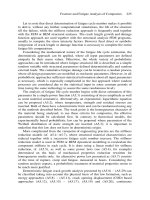
The motion of large-angle grain boundaries has been studied more thoroughly than
that of any other type of interface. Many measurements of thermally activated
motion have been made as a function of temperature, the geometric degrees of
freedom, driving pressure, specimen purity, etc. The results have been reviewed
[2,
131. According to the models described earlier, intrinsic motion is expected in
materials of extremely high purity at elevated temperatures under large driving
pressures.6 In addition, intrinsic mobilities of general boundaries should commonly
be higher than those of singular or vicinal boundaries because of insufficient den-
sities of kinks at dislocation-ledges on boundaries of the latter types. However, in
almost all cases, observed interface motion has been influenced to at least some
extent by solute-atom drag effects,
so
that the motion has been extrinsic and not
intrinsic. For example, general grain boundaries moved as much
as
three orders
of magnitude faster in A1 that had been zone-refined (see Section 22.1.2) using
twelve rather than four passes [14]. Also, as in Fig. 13.8, activation energies for
the motion of a number of
[loo]
tilt grain boundaries in 99.99995% pure A1 were
about half as large
as
the energies for corresponding boundaries in 99.9992% pure
Al. Such results show that grain boundary mobilities are extremely sensitive to
solute-atom drag effects, and can be strongly affected by them even at exceedingly
small solute-atom concentrations.
41
I
Purity
99.9992
0"""""'
0
10 20
30
40
50
Misorientation
8
(degrees)
Figure
13.8:
Activation energy,
EB,
for the motion
of
(100)
tilt boundaries in A1 as a
function
of
tilt angle. The arrows
at
the top indicate misorientations
of
singular boundaries.
Data for
A1
of
99.99995%,
99.9992%,
and
99.98%
purity.
From Fridman
et
al.
[15].
5Detailed analyses
of
these processes are given by Sutton and Balluffi
[2].
61f
motion
is
unaffected by drag effects due to impurity atoms, it is called
intrinsic.
316
CHAPTER
13:
MOTION OF CRYSTALLINE INTERFACES
The degree of solute segregation and drag is a function of the intrinsic grain-
boundary structure as well as the type and concentration of the solute atoms.
When solute drag is rate controlling, the intrinsic boundary structure is only one
of several factors that influences the drag and therefore the boundary mobility.
The interpretation of boundary-motion experiments solely in terms of the nature
of the intrinsic boundary structure then becomes rather indirect and exceedingly
treacherous.
For general boundaries, essentially all measurements are consistent with the lin-
ear relationship between velocity and pressure given by
Eq.
13.7 (i.e.,
'u
=
MBP),
as
might be expected on the basis of the preceding shuffling model. Available mobility
data have been collected for the motion of general grain boundaries in exception-
ally high-purity A1 and the activation energy
of
55
kJ
mol-' is significantly lower
than that of boundary self-diffusion, which is expected to be about 69 kJ mol-I
[2].
Also, the data can be
fit
to the uncorrelated atom-shuffling model for intrinsic mo-
tion in Section 13.3.3 using reasonable values of the parameters. These results are
at least consistent with the shuffling mechanism.
Regarding the motion of singular or vicinal grain boundaries, Fig. 13.5 shows
direct electron microscopy images of dislocation-ledge spirals on such boundaries.
The importance of line defects with ledge-dislocation character to the mobility of
singular boundaries has been demonstrated in a particularly clear manner for highly
singular
(111)
twin boundaries in Cu [16]. These boundaries were essentially im-
mobile in the annealed state but became mobile after picking up dislocation line
defects which impinged upon them during plastic deformation. In other work,
electron-microscope observations of the motion of vicinal boundaries by atom shuf-
fling at pure ledges have been made [17-191. The motion of boundaries by shuffling
at pure ledges has also been studied by computer simulation [20].
Evidence from measurements of the generally faster intrinsic motion of general
boundaries relative to that of singular or vicinal boundaries has been collected [2].
The situation is complicated because the degree of solute segregation at singular or
vicinal boundaries is often expected to be lower than that at general boundaries.
The extrinsic mobilities of general boundaries may therefore be smaller than those
of singular or vicinal boundaries (because of increased solute-atom drag), while their
intrinsic mobilities may be larger. This supposition is at least partially supported
by the data in Fig. 13.8. Here, the relatively large activation energies for the motion
of general tilt boundaries in the 99.9992% material (having misorientations between
those of the singular boundaries indicated by the arrows) most probably arose from
strong drag effects associated with relatively strong impurity segregation at these
boundaries. This effect disappears in the higher-purity, 99.99995%, material. At
even higher purity, the situation could reverse and the activation energies for the
general boundaries could become lower than for the singular boundaries [13].
Observations of further solute-atom drag effects have been reviewed
[2,
131. A
number of effects measured as a function of driving pressure, temperature, and
solute concentration appear to follow the general trends indicated in Fig. 13.6.
The approximate nature of the model makes some discrepancies unsurprising. In
Fig. 13.9, the discontinuous increases in boundary mobility as the temperature is
increased are presumably caused by successive detachments of portions of a solute-
atom atmosphere that exerted
a
drag on the boundaries.
13
4.
NONCONSERVATIVE MOTION
317
-
-2
v)
c
3
.I-
2;
-8
1.1
1.2
1.3
1.4
1.5
1000/T
(K-I)
Figure
13.9:
Experimentally determined plot
of
lnMB
vs.
1/T
for
a
(111)
tilt boundary
with
a
46.5'
tilt angle in A1 containing
Fe
solute atoms.
MB
=
boundary mobility.
From
Molodov
et
al.
1211.
13.4
NONCONSERVATIVE MOTION: INTERFACES AS SOURCES AND
SINKS FOR ATOMIC FLUXES
The basic mechanisms by which various types of interfaces are able to move non-
conservatively are now considered, followed by discussion of whether an interface
that is moving nonconservatively is able to operate rapidly enough as a source to
maintain all species essentially in local equilibrium at the interface. When local
equilibrium is achieved, the kinetics of the interface motion is determined by the
rate at which the atoms diffuse to or from the interface and not by the rate at
which the
flux
is accommodated at the interface. The kinetics is then
digusion-
limited.
When the rate is limited by the rate of interface accommodation, it is
source-limited.
Note that the same concepts were applied in Section
11.4.1
to the
ability of dislocations to act as sources during climb.
13.4.1
By
the Climb of Dislocations in Vicinal Interfaces.
The climb of the discrete lat-
tice dislocations that comprise small-angle grain boundaries allows them to act as
sources for fluxes of point defects (e.g., vacancies). In such cases, the various dislo-
cation segments in the array making up the boundary will attempt to climb in the
manner described for individual dislocations in Section
11.4.
However, they will
be constrained by the tendency to maintain the basic equilibrium structure
of
the
boundary array. In the simplest case of the symmetric tilt boundary illustrated in
Fig. 13.1, the edge dislocations will all be able to climb in unison relatively ea~ily.~
However, a pure twist boundary will act as a source only
if
the screw dislocations
are able to climb into helices as illustrated in Fig. 11.10. This climb process will
seriously perturb the structure of the boundary and will be possible only at large
driving forces (i.e., large super- or subsaturations of the point defects).
Figure 13.10 shows evidence for small-angle boundaries in
Au
acting as efficient
sinks for supersaturated vacancies under a large driving force. Here, the supersat-
urated vacancies have collapsed in the form of vacancy precipitates in the region of
Source Action of Sharp Interfaces
7Note that this process will cause the boundary
to
move relative to inert markers embedded in
either crystal adjoining the boundary.
318
CHAPTER
13
MOTION
OF
CRYSTALLINE INTERFACES
Figure
13.10:
Denudation
of
vacancy precipitation
in
~1
zone lying alongside a sniall-
angle grain boundary in quenched and subsequently anneitled Ail. The boundary (lower
right) acted
as
a
sink
for
the supersaturated vacancies. Vacancy precipitates are sniall
dislocation configurations resulting
from
the collapse
of
vacancy aggregates
(as
illustrated
sclieniatically in Fig.
11.15).
From
Siege1
et
a1
(221
the bulk away from the boundary. However, a precipitate-denuded zone is present
adjacent to the boundary due to the annihilation of supersaturated vacancies in
that region by the sink action of the boundary.
Large-angle singular
or
vicinal grain boundaries containing localized line defects
with dislocation-ledge character can also act
as
sources for point defects by means
of
the climb (and possibly accompanying glide) of these defects across their faces.
The patches of coherent interface between the line defects remain inactive since they
are relatively stable and difficult to perturb. The source efficiency then depends
upon the ability
of
the climbing dislocations to collect
or
disperse the point defects
by diffusion along their lengths as well as in the grain-boundary core. (Note the
similarity of this situation to the growth of a crystal at a vicinal surface in a
supersaturated vapor
as
in Fig. 12.3.)
A
vicinal grain boundary acting
as
a sink for supersaturated self-interstitial de-
fects is shown in Fig. 13.11. The interfacial line defects needed to support the source
action may often be produced by impinged lattice dislocations as in Fig. 13.4. How-
ever, at sufficiently high driving forces, the necessary line defects with dislocation
character may be nucleated homogeneously in the boundary in the form of small
loops possessing ledge character.8 In the case of supersaturated point defects, the
free energy to nucleate such a loop may be written approximately as
nR2('*
'1
Edefect
(13.13)
pb2
R
AF=-~n(~)-l]+2nRfL- 2(1
-
v)
R
where
R
is the loop radius,
f
is the energy per unit length of ledge, and
Edefect
is
the energy supplied per precipitated defect. The first term
is
the elastic energy of
the loop, the second the core-ledge energy, and the third the energy supplied by the
precipitated point defects. For a material with a high vacancy supersaturation, such
as
one subjected to high-temperature annealing and rapid quenching, Eq. 13.13 may
be used to evaluate AF, and it may then be shown that loops may be nucleated
at
significant rates. During high-energy irradiation, boundaries can act
as
sinks for
highly super-saturated self-interstitials by the nucleation (and subsequent growth)
8NNucleatiori theory
is
presented
in
Chapter
19.
13
4
NONCONSERVATIVE MOTION
319
Figure
13.11:
Experimentally observed climb of extrinsic grain-boundary dislocations
A.
B.
and
C
in vicinal
(001)
twist grain boundary in Au. Static array of screw dislocations
in background accommodates the twist deviation of the vicinal boundary shown from the
crystal misorientation of the nearby singular twist boundary to which it is vicinal. Excess self-
interstitial defects were roduced in the specimen by fast-ion irradiation and were destroyed
at the grain-boundary &locations by climb, causing the boundary to act as a defect sink.
(a)
Prior to irradiation.
(b)
Same area as in (a) after irradiation.
(c)
Diagram showing the
extent of the climb.
From
Komen
et
al
[24]
of boundary dislocation loops
[23].
Triangular dislocation loops formed on twin
boundaries in irradiated Cu are shown in Fig.
13.12.
Experimental evidence shows generally that vicinal grain boundaries can act as
efficient sinks for point defects under high driving forces where grain boundary
dislocation climb is possible
[a].
In the case of large-angle boundaries, line defects
with dislocation character may be generated as the boundary absorbs vacancies
from the bulk. However, at low driving forces the efficiency is often relatively low.
Vicinal heterophase interfaces can act as overall sources (or sinks) for fluxes
of solute atoms by the motion across their faces of line defects possessing both
dislocation and ledge character
of
the general type illustrated in Fig.
B.6.
The line
defects act as line sources; during their lateral motion, lattice sites are shuffled from
one adjoining crystal to the other, and the interface moves with respect to both
phases.
If
the two phases adjoining the interface have different compositions, solute
atoms must be either supplied or removed at the ledge by long-range diffusion. The
motion of the ledge is therefore essentially
a
shuffling process coupled to the long-
range diffusional transport of solute atoms.
Figure
13.13
illustrates how platelet precipitates grow and thicken by the
move-
ment of line defects of the type just described. The efficiency
of
the growing precip-
itate platelet as
a
sink for the flux of incoming solute atoms then depends upon the
density of ledges and their ability to move while incorporating the solute atoms.
320
CHAPTER
13:
MOTION
OF
CRYSTALLINE INTERFACES
Figure
13.12:
(111)
twin boundary in Cu acting as
a
sink for excess self-interstitial
defects produced by
1
MeV electron irradiation. Defects are destroyed by aggregating in the
boundary and then collapsing into triangular grain-boundary dislocation loops as illustrated
schematically in Fig.
11.15.
Once formed, the loops destroy further defects by climbing (and
expanding).
Micrograph provided by
A
H
King
Figure
13.13:
(a)
Ag,A1 precipitates in the form of thin platelets in Al-Ag alloy. The
broad faces of the platelets are parallel to
(111)
planes of the matrix, which lie at different
angles to the viewer.
(b)
Precipitate platelets in Cu-A1 alloy. Line defects that possess both
dislocation and ledge character are present on the broad faces. Platelets grow in thickness
by climb of these line defects across their faces.
From Rajab and Doherty
1251
and Weatherly
[26]
Available experimental information about the source (or sink) efficiency of het-
erophase interfaces for fluxes of solute atoms indicates that low efficiencies are
often associated with
a
lack of appropriate ledge defects
[2].
By
the Uncorrelated Shuffling
of
Atoms in General Interfaces.
Homophase and het-
erophase interfaces that are general with respect to all degrees of freedom are inco-
herent interfaces unable to sustain localized line defects. However, in many cases,
such interfaces are able to act as highly efficient sources for fluxes of point defects or
solute atoms by means of atom shuffling in the interface core. The process may be
modeled by assuming that the core is
a
slab of bad material containing
a
density
of
favorable sites where point defects can be created and destroyed, or where atomic
sites containing solute atoms can be transferred across the interface, by the uncorre-
lated local shuffling of atoms. It has been shown that high source efficiencies can be
obtained in many cases for reasonably low densities
of
the favorable sites
[2].
From
experimental results, this appears to be the case for homophase (grain) bound-
13
4
NONCONSERVATIVE
MOTION
321
aries as sources for point defects. However, it may not be the case for heterophase
boundaries when one
of
the adjoining phases has a relatively high binding energy
and a correspondingly high melting temperature and thermodynamic stability.
13.4.2
Diffusion-Limited
Vs.
Source-Limited Kinetics
The efficiency of an interface as a source or sink can be specified by using the same
parameter,
q,
which defined the source or sink efficiency
of
climbing dislocations
(see Eq.
11.25).’
To
illustrate this explicitly under diffusion- and source-limited
conditions, consider the rate at which a dilute concentration
of
supersaturated
B
atoms, which are interstitially dissolved in an A-rich
a
solution, diffuse to a distribu-
tion of growing spherical B-rich @-phase precipitate particles during a precipitation
process. The rate depends upon the efficiency of the
a/@
interfaces
as
sinks for the
incoming
B
atoms. Consider first the case where the interfaces perform
as
ideal
sinks and the solute concentration at each
a/@
interface is therefore maintained at
the equilibrium solubility limit of the
B
atoms in the
a
phase,
c$.
If the particles
are initially randomly distributed, an approximately spherically symmetric diffu-
sion field will be established around each particle in a spherical cell as in Fig. 13.14.
The problem of determining the rate at which the
B
atoms precipitate is then re-
duced to solving the appropriate boundary-value diffusion problem within a given
cell. The particle radius is
R
and the cell radius is given, to a good approximation,
by
R,
=
[3/(4~n)]l/~, where
n
is the density of precipitate particles. We assume
that the particle radius is always considerably smaller than the cell radius and first
find a solution for the case where the particle radius is assumed (artificially) to be
constant during the precipitation. The more realistic case where it increases due
to the incoming flux
of
B
atoms is then considered.
The diffusion equation is
&/at
=
DgV2c,
where
DB
and
c
are, respectively, the
diffusivity and concentration of the
B
atoms in the
a
phase. The initial condition
Figure
13.14:
Spherical diffusion cells surrounding particles during precipitation.
gMuch
of
this section
closely follows
Interfaces
in
Crystalline Materials,
by
A.P.
Sutton and
R.W.
Balluffi
[2].
322
CHAPTER
13:
MOTION
OF
CRYSTALLINE INTERFACES
in the cell is
c(r,O)
=
co
and the boundary conditions are
c(R,
t)
=
ce"4p
[TI.=,.
=
0
(13.14)
(13.15)
The separation-of-variables method (Section
5.2.4)
then gives the series solu-
tion
[27]
OL?
c(r,
t)
=
ce"9p
+
5
e-'TDBt
sin
[&(r
-
R)]
r
(13.16)
i=O
where the eigenvalues,
Xi,
are the roots of
tan[Xi(R,
-
R)]
=
XiR,
(
13.17)
and the coefficients, ai, are given by
2(c0
-
c,*,~)R(x~R~
+
1)
ai
=
Xi[XiR?(R,
-
R)
-
R]
(13.18)
The diffusion current into the particle carried by the ith term in the series given
in Eq.
13.16
is
Ii
=
4.rrR2D~
[d~/dr],=~
The total diffusion current into the particle is therefore a sum of the terms given
by Eq.
13.19.
Each term decays exponentially with a characteristic relaxation time
corresponding to
Ti
=
1/X;DB.
When
R
<<
R,,
all
of
the short-wavelength terms decay very rapidly compared
to the lowest-order
i
=
0
term, which, with acceptable accuracy, is
I,
=
47rD~
(c,
-
cz!)
R
e-tlTo
(
13.20)
where
ro
=
R~/~DBR [27].
Letting
(c)
be the average concentration in the spherical
cell,
(13.21)
Integrating Eq.
13.21
and combining the result with Eq.
13.20
leads to the remark-
ably simple expression for the total diffusion current entering the particle:
I
=
4.irD~R
((c)
-
c$)
(13.22)
The analysis shows that the diffusion current quickly settles down to the value given
by Eq.
13.22
during all but very early times and that the transients which occur at
the early times due to the higher-order eigenfunctions can be neglected whenever
the degree of precipitation is significant. Because the effects of any transients are
13
4
NONCONSERVATIVE
MOTION
323
small, Eq.
13.22
also describes, with acceptable accuracy, the instantaneous quasi-
steady current of atoms to the particle when it is growing due to the incoming
diffusion. Section
20.2.1
(see Eq.
20.47)
shows that Eq.
13.22
also holds with
acceptable accuracy for an isolated sphere which is growing in an infinite matrix.
It also holds for an isolated sphere of constant radius in an infinite matrix (see
Exercise
13.6).
The result given by Eq.
13.22
is therefore insensitive to the effects
due to sphere growth or to the volume in which it is growing as long as
R
<<
R,.
In Exercise
13.8
this result is used to determine the growth of the precipitates in
Fig.
13.14
as a function of time.
The situation becomes quite different when the
alp
interface is no longer capa-
ble of maintaining the Concentration of
B
atoms in its vicinity at the equilibrium
value
czt.
If the concentration there rises to the value
cap,
the instantaneous
quasi-steady-state current of atoms delivered to the particle by the diffusion field
(obtained from Eq.
13.22)
will be given by
I
=
4.irD~R
((c)
-
Pa)
(13.23)
This must be equal to the rate at which these atoms are incorporated into the
particle locally
at
the interface. The rate at which
B
atoms in the matrix transfer
to the particle across the
alp
interface will be proportional to the local matrix
concentration. The reverse rate of transfer from the particle to the matrix will
be the same as the rate of transfer from the matrix to the particle that would
occur under equilibrium conditions when detailed balance prevails. The net rate of
transfer will then be
I'
=
4.irR2K
(c"~
-
c$)
(13.24)
where
K
is a rate constant. This rate-constant model should apply over a range
of situations and has been widely used in the literature. The rate at which in-
coming
B
atoms are permanently incorporated in the particle depends upon the
product of the impingement rate of
B
atoms on the particle (which is proportional
to the
B
atom concentration in the matrix at the interface) and the fraction of the
impinging
B
atoms that is permanently incorporated (this fraction depends upon
the efficiency with which the particle collects and incorporates these atoms). This
efficiency depends upon sink characteristics of the interface, such as the density
of incorporation sites, the binding energy of a
B
atom to the interface, and its
rate of diffusion along the interface. These factors can be lumped together in the
form of a rate constant,
K,
so
that the rate of permanent incorporation (per unit
area of interface) is expressed as the product
Kc"0.
The rate at which
B
atoms
are permanently removed from the particle at the interface can be determined by
a stratagem in which the particle (with the identical interfacial sink structure) is
imagined to be in detailed balance with the equilibrium concentration of
B
atoms
in the matrix. The rate of permanent removal is then equal to the rate of per-
manent incorporation. However, the rate of incorporation depends upon the same
rate constant as in the nonequilibrium case and is therefore given by
Kc$.
This
must also be equal to the rate of permanent removal because of the detailed bal-
ance. However, it will also be equal to the rate of removal under nonequilibrium
conditions since the sink structure is assumed to be unchanged. The net rate of
incorporation (per unit area) in the nonequilibrium situation is then
K(c"@
-
c::).
The magnitude of the rate constant.
K.
can vary widely depending upon the sink
efficiency of the particle and it can evolve with time if the structure of the interface
324
CHAPTER
13:
MOTION
OF
CRYSTALLINE INTERFACES
(sink) changes.
A
detailed analysis of the analogous problem
of
crystal growth due
to the impingement of atoms from the vapor phase in Exercises
12.1
and
12.2
shows
that the growth rate can be represented by a rate-constant expression of similar
form. Setting
I
=
I',
solving for
cap,
and putting the result into
Eq.
13.23 yields
the rate of precipitation
(13.25)
which is smaller than the rate
of
precipitation under diffusion-limited conditions
(Eq.
13.22)
by the factor
1
+
DB/(KR).
In fact, the efficiency of the particle as a
sink is just
1
1
(13.26)
rl
=
1
+
DB/(KR)
if
the previous definition of the efficiency given by
Eq.
11.25 is employed. When the
transfer rate is very high (or the diffusivity is very small)
so
that
DB/(KR)
<<
1,
2
1,
caO
E
c$,
and the kinetics is diffusion-limited. At the other extreme, when
DB/(KR)
>>
1,
q
E
0,
cap
E
(c), and the kinetics is source-limited. When the
kinetics is between these limits, it is regarded as
rnixed.l0
Bibliography
1.
2.
3.
4.
5.
6.
7.
8.
9.
10.
11.
12.
13.
R.W. Cahn. Recovery and recrystallization. In R.W. Cahn and P. Haasen, editors,
Physical Metallurgy,
pages 1595-1671. North-Holland, Amsterdam, 1983.
A.P. Sutton and R.W. Balluffi.
Interfaces
in
Crystalline Materials.
Oxford University
Press, Oxford, 1996.
J.W. Christian.
The Theory
of
'Pransformations
in
Metals and Alloys.
Pergamon
Press, Oxford, 1975.
J.P. Hirth and
J.
Lothe.
Theory
of
Dislocations.
John Wiley
&
Sons, New York, 2nd
edition, 1982.
C. Herring. Diffusional viscosity of a polycrystalline solid.
J.
Appl. Phys.,
21:437-445,
1950.
C. Herring. Surface tension as
a
motivation for sintering. In W.E. Kingston, editor,
The
Physics
of
Powder Metallurgy,
pages 143-179, New York, 1951. McGraw-Hill.
W.T. Read.
Dislocations
in
Crystals.
McGraw-Hill, New York, 1953.
H. Gleiter. The mechanism of grain boundary migration.
Acta Metall.,
17(5):565-573,
1969.
D.J.
Dingley and R.C. Pond. On the interaction of crystal dislocations with grain
boundaries.
Acta Metal
l.,
27( 4) :667-682, 1979.
J.W. Cahn. The impurity-drag effect in grain boundary motion.
Acta Metall.,
E.
Nes, N. Ryum, and
0.
Hunderi. On the Zener drag.
Acta Metall.,
33:ll-22, 1985.
M.F.
Ashby. The influence of particles on boundary mobility.
In N. Hansen, A.R.
Jones, and
T.
Leffers, editors,
Recrystallization and Grain Growth
of
Multi-Phase
and Particle Containing Materials,
pages 325-336, Roskilde, Denmark, 1980. Riso
National Laboratory.
G. Gottstein and
L.S.
Shvindlerman.
Grain Boundary Migration
in
Metals: Thermo-
dynamics, Kinetics, Applications.
CRC Press, London, 1999.
10(
9)
:
789-798, 1962.
"See
Exercise
13.7
for
further
results.
EXERCISES
325
14. K.T. Aust and J.W. Rutter. Effect of grain boundary mobility and energy on preferred
orientation in annealed high purity lead.
Trans. AIME,
224:lll-115, 1962.
15. E.M. Fridman, C.V. Kopezky, and
L.S.
Shvindlerman. Effects of orientation and
concentration factors
on
migration of individual grain-boundaries
in
aluminum.
Z.
Metallkd.,
66(9):533-539, 1975.
16. P.R. Howell, J.O. Nilsson, and G.L. Dunlap. The effect of creep deformation
on
the
structure of twin boundaries.
Phil. Mag. A,
38(1):39-47, 1978.
17. D.A. Smith, C.M.F. Rae, and C.R.M. Grovenor. Grain boundary migration. In R.W.
Balluffi, editor,
Grain Boundary Structure and Kinetics,
pages 337-571, Metals Park,
OH,
1980. American Society for Metals.
18. H. Ichinose and
Y.
Ishida. In situ observation of grain boundary migration
of
silicon
C3 boundary and its structural transformation at
1000
K.
J.
Phys.
Colloq.
(Paris),
5l(suppl. no. l):C1:185-190, 1990.
19.
T.
Kizuka, M. Iijima, and
N.
Tanaka. Grain boundary migration
at
atomic scale in
MgO.
Muter. Sci. Forum,
233-234:405-412, 1997.
20. R.J. Jahn and P.D. Bristowe. A molecular dynamic study of grain boundary migration
without the participation of secondary grain boundary dislocations.
Scripta Metall.,
24(7):1313-1318, 1990.
21. D.A. Molodov, C.V. Kopetskii, and L.S. Shvindlerman. Detachment of a special
(C
=
19,
(111))
tilt boundary from an impurity in iron-doped aluminum bicrystals.
Sow.
Phys. Solid State,
23(10):1718-1721, 1981.
22. R.W. Siegel, S.M. Chang, and R.W. Balluffi. Vacancy loss at grain-boundaries in
quenched polycrystalline gold.
Acta Metall. Muter.,
28(3):249-257, 1980.
23. A.H. King and D.A. Smith.
On
the mechanisms of point-defect absorption by grain
and twin boundaries.
Phil. Mag. A,
42(4):495-512, 1980.
24.
Y.
Komem,
P.
Petroff, and R.W. Balluffi. Direct observation of grain boundary dis-
location climb in ion-irradiated gold bicrystals.
Phil. Mag.,
26:239-252, 1972.
25. K.E. Rajab and R.D. Doherty. Kinetics of growth and coarsening of faceted hexagonal
precipitates in an fcc matrix.
1.
Experimental-observations.
Acta Metall. Muter.,
37( 10):2709-2722, 1989.
26. G.C. Weatherly. The structure of ledges at plate-shaped precipitates.
Acta Metall.,
27. F.S. Ham. Theory of diffusion limited precipitation.
J.
Phys. Chem. Solids,
6(4):335-
19(3):181-192, 1971.
351, 1958.
EXERCISES
13.1
Consider the conservative motion of a heterophase
alp
interface in an
A-B
binary system.
cs,
cg,
c:,
and
c$
are the concentrations of
A
and
B
in the
two phases facing each other across the interface. Show that the conservative
motion requires that
Xz
=
X$
and that
it
is generally expected that
c2
#
SoZution.
If
the interface moves conservatively into the
LY
phase,
it
will convert a
slab
of
the
cy
phase
of
thickness
be
into a slab
of
,8
phase
of
thickness
bP.
Each
slab must contain the same number
of
A
and
B
atoms
(it,
NZ
=
N$
=
NA
and
NE
=
N$
=
NB).
Each slab will then have the same mass, but because the slab
Ct.
326
CHAPTER
13:
MOTION
OF
CRYSTALLINE INTERFACES
densities will generally differ, the slab thicknesses will generally differ. The condition
X:
=
X$
must then be satisfied since
=
x$
NA
NA
-t
NB
x;
=
However, since (for unit area of boundary)
NA
NA
cz
=
-
and
cp
-
-
A-
60
6"
(13.27)
(13.28)
the concentrations will be expected to differ since in general
6"
#
bP.
13.2
Equation 13.1 for the pressure exerted on the small-angle tilt boundary by
a shear stress was derived by considering the work done by the shear stress
during the change in macroscopic shape of the bicrystal which occurred when
the boundary moved (see Fig. 13.1). Obtain the same result by considering
the force exerted on each moving edge dislocation by the applied stress and
summing the forces on all dislocations.
Solution.
Using
Eq.
11.2,
the force per unit length on each dislocation
is
fo
=
uxyb.
The spacing,
d,
of the dislocations in a symmetric tilt boundary is
d
=
b/0
[7].
The
pressure on the boundary due to all dislocations
is
then
(13.29)
1
0
d b
P
=
axyb
-
=
uz,b
-
=
0Zy0
Note that this result
is
expected since the force exerted on an individual dislocation by
a
stress is the result of the change in crystal shape that occurs when the dislocation moves.
Since the change in shape of the bicrystal due to the boundary motion
is
just the sum
of
the changes due to the motion of each of its individual dislocations, the total force
on the boundary must be just the sum of the forces on the individual dislocations.
13.3
An expression for the diffusion potential at an edge dislocation in a small-
angle tilt boundary subjected to a pure shear stress has been derived in Sec-
tion 13.3.2. Derive a general expression for the diffusion potential at an iso-
lated general (mixed) straight dislocation acted on by a general stress field.
Express your answer in terms of the stress tensor,
u,
the Burgers vector,
b,
and the unit tangent vector,
(.
Remember that the potential is related to the
work performed by the stress field when an atom
is
inserted at the dislocation
(per unit dislocation length) during the dislocation climb. The force exerted
on the dislocation
is
given by the Peach-Koehler equation (Eq. 11.1). Also,
only the edge component of the dislocation plays a role in the climb.
Solution.
The dislocation will climb in a direction perpendicular to its glide plane (i.e.,
the plane containing both b'and
0.
The unit normal,
A,
to the glide plane
is
-#
(13.30)
The force per unit length,
f,
exerted on the dislocation by the stress field in the climb
direction normal to the glide plane is then
+
f
=
f,.A
(13.31)
EXERCISES
327
13.4
The climb distance per unit length,
dc,
due to the insertion of an atom is
R
R
d
=-
c-
be
(Ax
r^)
'b'
(13.32)
where
be
=
(h
x
t)
.
6
is the magnitude of the edge component of the Burgers vector.
The potential relative to the reference potential,
pi,
is then the negative of the work
done by the stress during the climb and is therefore given by
Note that the sign
of
the final expression in
Eq.
13.33
must be consistent with the
convention for determining the Burgers vector (see the text following
Eq.
11.1).
A
single-phase bicrystal sheet of thickness,
h,
is produced in a laboratory and
cut into a symmetrical wedge
as
in Fig. 13.15. Upon heating, the boundary
Figure
13.15:
distance
L(0)
froin the apex.
Bicrystal specimen with a planar grain boundary initially located
a
is found to migrate toward the apex and data for
L(t)
as a function of time,
t,
are shown in Fig. 13.16.
t
(min)
Figure
13.16:
Migration data for boundary in Fig. 13.15
Develop
a
plausible model for the observed data in Fig. 13.16. State two
assumptions
of
the model.
Give a plausible explanation
for
the observed initial transient behavior
in Fig. 13.16.
Using only the information in Fig. 13.16, estimate the activation energy
for boundary motion.
328
CHAPTER
13
MOTION
OF
CRYSTALLINE INTERFACES
(d)
Closer examination of the data in Fig. 13.16 shows that growth is not uni-
form but oscillates between slow and fast growth, as shown in Fig. 13.17.
Give a plausible explanation
for
this behavior.
L2(
0)
-b
L2(t)
(mm2)
9
0
10
20
30
40
SO
t
(min)
Figure
13.17:
Magnified view
of
data. from Fig.
13.16
at
1000°C.
(e)
The same experiment is repeated, but the material is obtained from a
different supplier. Give a plausible explanation for the kinetic transition
which is now observed after about
30
minutes at
T
=
8OO0C, as in
Fig. 13.18.
0
10
20
30
LK)
50
t
(rnin)
Figure
13.18:
supplier.
Same experiment
as
for Fig.
13.16,
but with material from
a
different
Solution.
Assuming that the surface energies of grains
1
and
2
are the same and that the
grain-boundary energy is isotropic, the boundary will quickly adopt a circular-arc
shape which is perpendicular to the wedge edges in order to balance surface-tension
forces. The driving pressure on the boundary will then be
P
=
y/R,
where the
radius
of
curvature is
R
=
L/
cos(a/2).
Therefore,
Ya
P
=
-
cos
-
L2
Assuming a constant boundary mobility,
MB,
or
a!
L dL
=
-MBY~
cos
-
dt
2
(13.34)
(13.35)
EXERCISES
329
Integrating Eq. 13.35 yields
L2(0)
-
L2(t)
=
2M~y~
cos
cy
t
(13.36)
(b) The data indicate that the boundary motion corresponding to Eq. 13.36 does not
begin immediately. This could be the result of grain boundary pinning by solute
atoms or small precipitates or by the existence of a grain-boundary groove in the
initial position of the boundary from which the boundary must break away.
It
could
also be the result of time taken for the boundary to adopt the curved shape-a
process that would presumably begin from the specimen edge.
(c) Equation 13.35 indicates that the slope of the linear regions of the two curves
in Fig. 13.16
is
proportional to the boundary mobility,
MB.
Assuming that the
boundary energy,
yB,
is independent of temperature and that
MB
follows an
Arrhenius law,
MB
=
Mg
exp[-EB/(kT)],
the activation energy for migration
can be calculated. Letting
TI
=
1073
K
and
T2
=
1273
K,
the corresponding
mobilities are proportional to the slopes of the curves in Fig. 13.16:
2
4
19
-
2
=
0.082
and
MB(T~)
0:
-
=
0.23 (13.37)
MB(T1)
0:
From the Arrhenius law,
and hence
=
1.0
x
10-l~
J
-
1.054
x
1.38
x
lo-''
J
K-'
-
1.46
x
10-4
K-I
(13.38)
(13.39)
(d) The most likely explanation for jerky motion of the boundary is localized pinning by
precipitates or small inclusions from which the boundary must repeatedly escape.
(e) Figure 13.18 indicates that the boundary initially moves steadily at a relatively
slow rate, then undergoes a transition to steady motion at a higher rate. Such
behavior
is
consistent with an impurity-drag breakaway effect, which could be
due to certain impurities in the material from the different supplier. Note that
according to Eq. 13.34, the driving pressure increases as the boundary migrates
and
L
decreases. The initial slow migration regime takes place when the boundary
is less highly curved and is moving under a relatively small capillary driving force.
Under these conditions, the boundaries in the impure material could have an
impurity atmosphere that would have to move along with the boundary as
it
migrates with a relatively low mobility (extrinsic migration). As the boundary
moves toward the apex of the wedge-shaped bicrystal specimen,
it
becomes more
highly curved and the capillary driving force rises (ultimately becoming infinite).
When the driving force becomes sufFiciently high, the moving boundary can break
free of the impurity atoms and move with a higher intrinsic mobility.
13.5
Consider the pinned second-phase particle illustrated in Fig. 13.7 and de-
scribed by
Eqs.
13.9-13.12. Assume that
ypl
=
yp2, so
that
a
=
90".
(a)
Show that t,he force exerted by the interface on the particle (or alter-
nately, the force exerted by the particle on the interface) when the in-
terface is at a position where it meets the particle at the distance along