Lubrication and Reliability Handbook 2010 Part 4 ppt
Bạn đang xem bản rút gọn của tài liệu. Xem và tải ngay bản đầy đủ của tài liệu tại đây (553.3 KB, 20 trang )
A14 Selection of lubrication systems
A14.2
METHODS OF SELECTION
Table 14.1 Oil systems
Table 14.2 Grease systems
Table 14.3 Relative merits of grease and oil
systems
Table 14.4 Selection by heat removal
A14Selection of lubrication systems
A14.3
Table 14.5 Selection by type of component to be lubricated
Table 14.6 Selection by economic considerations
A14 Selection of lubrication systems
A14.4
Table 14.7 General selection by component. Operating conditions and environment
Selection of gear lubrication systems
A15Total loss grease systems
A15.1
TYPES OF TOTAL LOSS GREASE SYSTEMS AVAILABLE
A15 Total loss grease systems
A15.2
Considerations in selecting type of system
A15Total loss grease systems
A15.3
PIPE-FLOW CALCULATIONS
To attempt these it is necessary that the user should know:
(a) The relationship between the apparent viscosity (or shear stress) and the rate of shear, at the working
temperature;
(b) The density of the grease at the working temperature.
This information can usually be obtained, for potentially suitable greases, from the lubricant supplier in graphical form
as below (logarithmic scales are generally used).
A15 Total loss grease systems
A15.4
Typical pipe sizes used in grease systems
Typical data for flexible hoses used in grease systems
A15Total loss grease systems
A15.5
CONSIDERATIONS IN STORING, PUMPING AND TRANSMITTING GREASE AND GENERAL
DESIGN OF SYSTEMS
A16 Total loss oil and fluid grease systems
A16.1
GENERAL
Most total loss systems available from manufacturers are
now designed to deliver lubricants ranging from light
oils to fluid greases of NLGI 000 consistency.
Fluid grease contains approximately 95% oil and has
the advantage of being retained in the bearing longer
than oil, thus reducing the quantity required whilst
continuing to operate satisfactorily in most types of
system.
The main applications for total loss systems are for
chassis bearings on commercial vehicles, machine tools,
textile machinery and packaging plant.
Because of the small quantity of lubricant delivered by
these systems, they are not suitable for use where cooling
in addition to lubrication is required, e.g. large gear
drives.
Fluid grease is rapidly growing in popularity except in
the machine tool industry where oil is preferred.
All automatic systems are controlled by electronic or
electric adjustable timers, with the more sophisticated
products having the facility to operate from cumulated
impulses from the parent machine.
Individual lubricant supply to each bearing is fixed
and adjustment is effected by changing the injector unit.
However, overall lubrication from the system is adjusted
by varying the interval time between pump cycles.
Multi-outlet – electric or pneumatic
Operation: An electric or pneumatic motor drives cam-
operated pumping units positioned radially on the base
of the pump. The pump is cycled by an adjustable
electronic timer or by electrical impulses from the parent
machine, e.g. brake light operations on a commercial
vehicle.
Individual 4 mm OD nylon tubes deliver lubricant to
each bearing.
Applications: Commercial vehicles, packaging machines
and conveyors.
Specification:
Outlets: 1–60 (0.01–1.00 ml).
Pressure: To 10 MN/m
2
.
Lubricants: 60 cSt oil to NLGI 000 grease (NLGI 2
pneumatic).
Failure warning: Pump operation by light or visual
movement.
Cost factor: Low (electric), Medium (pneumatic).
Figure 16.1 Schematic Figure 16.2 Pump
Figure 16.3 Pumping unit
A16Total loss oil and fluid grease systems
A16.2
Single line – volumetric injection
Operation: The pump delivers lubricant under pressure
to a single line main at timed intervals. When the
pressure reaches a predetermined level, each injector or
positive displacement unit delivers a fixed volume of
lubricant to its bearing through a tailpipe.
When full line pressure has been reached the pump
stops and line pressure is reduced to a level at which the
injectors recharge with lubricant ready for the next
cycle.
Pumps are generally electric gear pumps or pneumatic
piston type. All automatic systems are controlled by
adjustable electronic timers but hand operated pumps
are available.
Main lubricant pipework is normally in 6 or 12 mm
sizes and tailpipes in 4 or 6 mm depending on the size of
system.
Applications: All types of light to medium sized manu-
facturing plant and commercial vehicles.
Specification:
Outlets: 1–500 (0.005–1.5 ml).
Pressure: 2–5 MN/m
2
.
Lubricants: 20 cSt oil to NLGI 000 grease.
Failure warning: Main line pressure monitoring.
Cost factor: Medium.
Figure 16.4
Figure 16.5
Figure 16.6 Positive displacement unit
A16 Total loss oil and fluid grease systems
A16.3
Single line-resistance (oil only)
Operation: A motor driven piston pump discharges a
predetermined volume of oil at controlled intervals to a
single main line. Flow units in the system proportion the
total pump discharge according to the relative resistance
of the units.
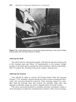
Care needs to be taken in the selection of components
to ensure each bearing receives the required volume of
lubricant; as a result, this type of system is used
predominantly for original equipment application.
Applications: Machine tools and textile machinery.
Specification:
Outlets: 1–100 (0.01–1 ml).
Pressure: 300–500 kN/m
2
.
Lubricants: 10–1800 cSt (Oil only).
Failure warning: line pressure monitoring.
Cost factor: Low.
Figure 16.7 Schematic
Figure 16.8 Pump
Figure 16.9 Flow unit
A16Total loss oil and fluid grease systems
A16.4
Single line progressive
Operation: An electric or pneumatic piston pump
delivers lubricant on a timed or continuous basis to a
series of divider manifolds. The system is designed in
such a way that if a divider outlet fails to operate, the
cycle will not be completed and a warning device will be
activated. Due to this feature, the system is widely used
on large transfer machines in the automobile industry.
Applications: Machine tools and commercial vehicles.
Specification:
Outlets: 200 (0.01–2 ml).
Pressure: 10 MN/m
2
.
Lubricants: 20 cSt oil to NLGI 2 grease.
Failure warning: Failure of individual injector can
activate system alarm.
Cost factor: Medium to high.
CHECK LIST FOR SYSTEM SELECTION AND
APPLICATION
Most economic method of operation – electric, pneu-
matic, manual, etc.
Cost installed – Max 2% of parent machine.
Degree of failure warning required – warning devices
range from low lubricant level to individual bearing
monitoring. Cost of warning devices must be balanced
against cost of machine breakdown.
Check pressure drop in main lines of single line systems.
Large systems may require larger pipe sizes.
Ensure adequate filtration in pump – Some types of
systems are more sensitive to dirt in the lubricant.
Is the system protected against the operating environ-
ment? e.g.: High/low temperature, humidity, pressure
steam cleaning, vibration/physical damage, electrical
interference etc.
If using flexible tubing, is it ultra violet stabilised?
If air accidentally enters the system, is it automatically
purged without affecting the performance?
Check for overlubrication – particularly in printing and
packaging applications.
Is the lubricant suitable for use in the system? (Additives
or separation.)
Reservoir capacity adequate? Minimum one month for
machinery, three months for commercial vehicles.
Accessibility of indicators, pressure gauges, oil filler caps,
etc.
Should system be programmed for a prelube cycle on
machine start up?Figure 16.10 Schematic
A17 Mist systems
A17.1
Mist systems, generically known as aerosol systems,
employ a generator supplied with filtered compressed air
from the normal shop air main, to produce a mist of
finely divided oil particles having little tendency to wet a
surface. The actual air pressure applied to the inlet of
the generator is controlled and adjusted to provide the
desired oil output.
The mist must be transmitted at a low velocity below
6 m/s and a low pressure usually between 25 and 50 mbar
gauge through steel, copper or plastic tubes. The tubes
must be smooth and scrupulously clean internally.
At the lubrication point the mist is throttled to
atmospheric pressure through a special nozzle whose
orifice size controls the total amount of lubricant applied
and raises the mist velocity to a figure in excess of 40 m/s.
This causes the lubricant to wet the rubbing surfaces and
the air is permitted to escape to atmosphere. Empirical
formulae using an arbitrary unit – the ‘Lubrication
Unit’, are used to assess the lubricant requirements of
the machine, the total compressed air supply required
and the size of tubing needed.
DESIGN
The essential parameters of components are indicated in
Table 17.2 and the load factors for bearings are given in
Table 17.1.
Table 17.1 Load factors
Table 17.2 Information required for the calculation of lubricant flow rates
A17Mist systems
A17.2
The Lubrication Unit (LU) rating of each component
should be calculated from the formulae in Table 17.3,
using the values in Tables 17.1 and 17.2.
Total the LU ratings of all the components to obtain
the total Lubrication Unit Loading (LUL). This is used
later for estimating the oil consumption and as a guide
for setting the aerosol generators.
Distribution piping
When actual nozzle sizes have been decided, the actual
nozzle loadings (measured in Lubrication Units) can be
totalled for each section of the pipework, and this
determines the size of pipe required for that section. The
actual relationship is given in Table 17.4 and Figures
17.2. Where calculated size falls between two standard
sizes use the larger size. Machined channels of appro-
priate cross-sectional area may also be used as distribu-
tion manifolds.
Nozzle sizes
Select standard nozzle fitting or suitable drilled orifice
size from Figure 17.1 for each component using its
calculated LU rating. Where calculated LU rating falls
between two standard fitting or drill sizes, use the larger
size fitting or drill. Multiple drillings may be used to
produce nozzles with ratings above 20 LU.
Maximum component dimensions (Table 17.1) for a
single nozzle.
b = 150 mm
w = 150 mm for slides, 12 mm for chains, 50 mm for
other components.
Where these dimensions are exceeded and for gear
trains or reversing gears use nozzles of lower LU rating
appropriately sized and spaced to provide correct total
LU rating for the component.
Table 17.3 Lubrication unit rating
Figure 17.1 Drill size and orifice ratings
Table 17.4 Pipe sizes
A17 Mist systems
A17.3
Generator selection
Total the nozzle ratings of all the fittings and orifices to
give the total Nozzle Loading (NL) and select generator
with appropriate LU rating based on Nozzle Loading.
Make certain that the minimum rating of the generator
is less than NL.
Air and oil consumption
Air consumption is a function of the total nozzle loading
(NL) of the system. Oil consumption depends on the
concentration of oil in the air and can be adjusted at the
generator to suit the total Lubrication Unit Loading
(LUL).
Air consumption
Using the total Nozzle Loading (NL), the approximate
air consumption can be calculated in terms of the
volume of free air at atmospheric pressure, from:
Air consumption = 0.015 (NL) dm
3
/s
Oil consumption
Using the total Lubrication Unit Loading (LUL), the
approximate oil consumption can be calculated from:
Oil consumption = 0.25 (LUL) ml/h
INSTALLATION
Locate nozzle ends between 3 mm and 25 mm from
surface being lubricated. Follow normal practice in
grooving slides and journal bearings. The positioning of
the nozzles in relationship to the surface being lubri-
cated should be similar to that used in circulation
systems. See Table 17.5.
Appropriate vents with hole diameters at least 1.5
times the diameter of the associated supply nozzle must
be provided for each lubrication point. If a single vent
serves several nozzles, the vent area must be greater than
twice the total area of the associated nozzles.
Follow instructions of aerosol generator manufacturer
in mounting unit and connecting electrical wiring. Avoid
sharp bends and downloops in all pipework. Consult BS
4807: 1991 ‘Recommendations for Centralised Lubrica-
tion as Applied to Plant and Mechinery’ for general
information on installation.
Select appropriate grade of lubricant in consultation
with lubricant supplier and generator manufacturer.
Figure 17.2 Sizing of manifolds and piping
A17Mist systems
A17.4
Table 17.5 Nozzle positioning
A18 Dip, splash systems
A18.1
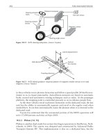
SPUR, BEVEL AND HELICAL GEARS
All gears, except very slow running ones, require complete enclosure. In general, gears dip into oil for twice tooth depth,
to provide sufficient splash for pinions, bearings, etc. and to reduce churning loss to a minimum.
Typical triple reduction helical gear unit
This has guards and tanks for individual gears. Bearings are fed by splash and from a trough round the walls of the case.
Suitable for up to 12.5 m/s (2500 ft/min) peripheral speed.
Typical single reduction bevel gear unit
Suitable for up to 12.5 m/s (2500 ft/min).
Typical high-speed gear unit guard
Normally satisfactory up to 25 m/s (5000 ft/min). With
special care can be used up to 100 m/s (20 000 ft/min).
Figure 18.1
Figure 18.2 Bevel unit with double row bearings
on pinion shaft
Figure 18.3 Typical bearing lubrication
arrangement with taper roller bearings
Figure 18.4
Figure 18.5 Peripheral speed against gear
diameter for successful splash lubrication to
upper bearings in dip-lubricated gear units
A18Dip, splash systems
A18.2
WORM GEARS
Typical under-driven worm gear unit
Oil is churned by the worm and thrown up to the top
and sides of the case. From here it drips down via the
wheel bearings to the sump.
A simple lip seal on a hard, ground shaft surface,
prevents leakage.
Oil level generally just below worm centre-line.
An oil scraper scrapes oil into a trough to feed the
wheel bearings.
Typical over-driven worm gear unit
Similar to under-driven worm gear unit except that the
worm is over the wheel at the top of the unit, and the oil
level varies in depth from just above wheel tooth depth to
almost up to the centre line of the wheel, depending
upon speed. The greater the speed, the higher the
churning loss, therefore the lower should be the oil level.
At low speeds, the churning loss is small and a large
depth of oil ensures good heat-transfer characteristics.
GENERAL DESIGN NOTES
Gears
In dip-splash systems, a large oil quantity is beneficial in
removing heat from the mesh to the unit walls and
thence to the atmosphere.
However, a large quantity may mean special care has to
be paid to sealing, and churning losses in gears and
bearings may be excessive. It is necessary to achieve a
balance between these factors.
Other applications
The cylinders and small-end bearings of reciprocating
compressors and automotive internal combustion
engines are frequently splash lubricated by oil flung from
the rotating components. In these applications the
source of the oil is usually the spill from the pressure-fed
crankshaft bearings. In some small single-cylinder com-
pressors and four-stroke engines, the cap of the connect-
ing rod may be fitted with a dipper which penetrates up
to 10 mm into the oil in the sump and generates splash
lubrication as a result. In lightly loaded applications the
big-end bearings may also be splash lubricated in this
way, and in some cases the dipper may be in the form of
a tube which scoops the oil directly into the big-end
bearing. In small domestic refrigeration compressors, a
similar system may also be used to scoop oil into the end
of the crankshaft, in order to lubricate all the crankshaft
bearings.
Figure 18.6
A19 Circulation systems
A19.1
A circulation system is defined as an oil system in which the oil is returned to the reservoir for re-use. There are two
groups of systems: group 1, lubrication with negligible heat removal; and group 2, lubrication and cooling.
GROUP 1 SYSTEMS
Virtually any form of mechanically or electrically driven pump may be used, including piston, plunger, multiplunger,
gear, vane, peristaltic, etc. The systems are comparatively simple in design and with low outputs. Various metering devices
may be used.
Multiplunger pump systems
These systems utilise the plunger-type oil lubricators of the rising or falling drop type, employing a separate pumping
element for each feed, giving individual adjustment and a positive feed to each lubrication point. Generally, the
lubricators have up to some 32 outlets with the discharges being adjustable from zero to maximum.
Typical applications
Paper machines, large kilns, calenders, and general machinery with a large number of bearings requiring a positive feed
with feed adjustment.
Figure 19.1 Simple multipoint
lubricator – system contains
barest elements of pump reservoir
and interconnecting pipework
Figure 19.2 Multi-point lubricators
mounted on receiving tank –
system has the advantage of
providing setting time and better
filtration of returned oil
Figure 19.3 Extensive system for
large numbers of bearings, using
multi-point lubricator system can
be extended within the limitation
of the gravity feed from the header
tanks
A19Circulation systems
A19.2
Positive-split systems
In general these systems deliver a larger quantity of lubricant than multiplunger systems. They comprise a small high-
pressure pump with or without stand-by, fitted with integral relief valve supplying lubricant to the bearings via positive
dividers. These dividers then deliver the oil to the bearings in a predetermined ratio of quantities. By use of a
microswitch operated by the indicator pin on the master divider (or single divider if the number of points is small),
either timed automatic or continuous operation is available. The microswitch can also be used to give a warning of
failure of the system.
Typical applications
Machine tools, sugar industry, gearboxes, printing machines, and special-purpose machinery.
Figure 19.4