Chemical Degradation Methods for Wastes and Pollutants - Chapter 9 pot
Bạn đang xem bản rút gọn của tài liệu. Xem và tải ngay bản đầy đủ của tài liệu tại đây (702.19 KB, 51 trang )
9
Permeable Reactive Barriers of Iron
and Other Zero-Valent Metals
Paul G. Tratnyek
Oregon Health and Science University, Beaverton, Oregon, U.S.A.
Michelle M. Scherer
University of Iowa, Iowa City, Iowa, U.S.A.
Timothy L. Johnson
AMEC Earth & Environmental, Inc., Portland, Oregon, U.S.A.
Leah J. Matheson
MSE Technology Applications, Inc., Butte, Montana, U.S.A.
I. INTRODUCTION
A. Historical Context
The ‘‘modern’’ history of the use of zero-valent metals (ZVMs) in the
remediation of contaminated water has been summarized from several
perspectives [1–4]. By most accounts, the critical event was the serendipitous
discovery that trichloroethene (TCE) is degraded in the presence of the
metal casing materials used in some groundwater monitoring wells [5]. This
observation led to recognition that granular iron metal might be applicable
to the remediation of groundwater that is contaminated with chlorinated
solvents. Around the same time, the possibility of engineering permeable
treatment zones for in situ treatment of contaminated groundwater had led
to a search for suitable reactive media, and granular iron quickly became
the most promising reactive medium for application in permeable treatment
zones [6]. The confluence of these two developments (granular iron and
permeable treatment zones) made the emergence of reactive barriers
TM
Copyright © 2003 by Marcel Dekker, Inc. All Rights Reserved.
containing granular iron into one of the landmark developments in the
history of groundwater remediation technology.
The rapid development of this technology over the last decade has been
accompanied by a conspicuous increase in the quantity of published infor-
mation on the reaction of iron metal with organic and inorganic solutes in
aqueous systems. With so much activity in the present, it is easy to overlook
how much relevant work was done earlier. For example, the electrolytic
deposition of dissolved metals onto ZVMs has long been known to chemists,
and the potential for application of this chemistry to water treatment was
recognized at least as far back as the 1960s [7]. Similarly, the use of ZVMs to
perform selective reductions for organic synthesis was already well docu-
mented by the 1920s (e.g., Refs. 8 and 9), and environmental applications had
been descri bed by the 1980s [10,11]. In fact, prior to 1990, there ha d already
been several detailed ‘‘process-level’’ studies on the removal of organics (e.g.,
Refs. 12–15) and inorganics (e.g., Refs. 7, 16, and 17). This early work was
very widely dispersed, however, and a unified understanding of the processes
responsible for contaminant removal by ZVMs has only recently begun to
take shape.
B. Scope
The scope of this review is centered around permeable reactive barriers
(PRBs) of ZVMs. Among the ZVMs used in remediation applications, iron
metal (ZVI or Fe
0
) is by far the most important. PRBs of ZVI (sometimes
designated FePRBs) are the technology known colloquially as ‘‘ iron walls.’’
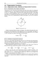
However, as illustrated in Fig. 1, not all PRBs are made from ZVMs and not
all remediation applications of ZVMs are PRBs.
1. Permeable Reactive Barriers
Technologies for treatment of subsurface contamination can be divided into
‘‘ex situ’’ methods that involve removal of the contaminated material for
treatment at the surface and ‘‘ in situ’’ methods where the treatment is applied
to the subsurface. In situ treatment technologies include a variety of related
methods such as continuous trenches, funnel-and-gates, passive reactive
wells, geochemically manipulated zones, and biologically reactive zones.
Continuous trenches and funnel-and-gates are the most common types of
PRBs [18,19]. At least one formal definition of a PRB has been given [3], but
for the present purpose we prefer a slightly narrower and simpler definition:
‘‘a permeable subsurface zone constructed of reactive material that is
oriented to intercept and destroy or immobilize contaminants.’’ The major
elements of a PRB are shown in Fig. 2.
Tratnyek et al.372
TM
Copyright © 2003 by Marcel Dekker, Inc. All Rights Reserved.
In contrast to the conventional PRB, a permeable reactive treatment
zone (PRTZ) is a geochemically manipulated subsurface zone where aquifer
material is altered to promote destruction or immobilization of target
chemicals (e.g., flushed with sodium dithionite to create a zone of reduced
iron [20–23]). Passive reactive wells (PRWs) are a series of wells or caissons
containing a treatment material, through which water flows because of a
permeability contrast between the wells and aquifer. A biologically reactive
barrier (BRB), sometimes called a ‘‘biocurtain,’’ is a subsurface zone where
microbiological activity is enhanced or modified to provide treatment of
target chemicals.
2. Reactive Media
The core function of a PRB (and many related technologies) is to bring the
contaminated material in contact with a reactive material that promotes a
process that results in decontamination. The range of reactive materials that
can be applied in PRBs is quite diverse, as illustrated by Table 1. The
Figure 1 Venn diagram showing the relationship between various types of PRBs
and various remediation applications of ZVMs. The intersection of these two
categories represents PRBs with ZVI as the reactive medium (i.e., FePRBs or
‘‘iron walls’’).
Permeable Reactive Barriers 373
TM
Copyright © 2003 by Marcel Dekker, Inc. All Rights Reserved.
Figure 2 Typical configuration of a PRB, showing the source zone, plume of
contamination, treatment zone, and plume of treated groundwater. (Reprinted with
permission, Powell and Associates.)
Table 1 Summary of Reactive Media
a
Type Composition Applications
Selected
references
Zero-valent metals Fe, Zn, Sn TCE, Cr(VI), etc. Numerous
b
Bimetallic
combinations
Fe/Ni, Fe/Pd PCBs, chlorophenols,
chloromethanes,
[24–26]
Metal oxides Iron oxides Cr(VI), U(VI) [20,21,23,27–30]
Metal sulfides FeS Chloromethanes,
ethanes, and ethenes
[31,32]
Aluminosilicates Clays, Zeolites TCE, Cr(VI) [33–35]
Calcium phosphates Apatite, bone char U(VI), Pb [36,37]
Carbonaceous
materials
Peat, sawdust, leaf
litter, ground rubber
Phosphate, BTEX,
Acid Mine Drainage
[38–41]
a
Other tables of this type can be found in Refs. 4, 30, and 42.
b
Complete list at />Tratnyek et al.374
TM
Copyright © 2003 by Marcel Dekker, Inc. All Rights Reserved.
reactive material can be introduced directly into the subsurface or formed in
situ after addition of agents that are not directly involved in reaction with the
contaminants. The former is exemplified by ZVMs, whereas the latter is
exemplified by the zone of ferrous iron formed by ‘‘in situ redox manipu-
lation’’ [20–23]. In Table 1, we have tried to capture the whole range of
reactive media that are currently being used in PRBs, but the remainder of
this revie w will focus on PRBs constructed with ZVMs.
C. Other Sources of General Information on ZVI and PRBs
The rapid increase in interest and knowledge associated with remediation
applications of ZVMs and PRBs has led to a number of revie ws on these
subjects. To date, these include Refs. 2, 3, 18, and 42–53. In general, these
reviews do not attempt to provide comprehensive coverage of the primary
literature in this field, as it has already become too vast. Fortunately, most
of the primary literature is included in several databases that are available
on the World Wide Web. These databases can be found at .
ogi.edu/ironrefs and .
II. CONTAMINANT-REMOVAL PROCESSES
The processes responsible for contaminant removal by ZVMs and PRBs
include both ‘‘ physical’’ removal from solution to an immobile pha se
and ‘‘chemical’’ removal by reaction to form less hazardous products. In
the discussion that follows, we will refer to the former as sequestration
and the latter as transformation. This distinction has heuristic value,
even though sequestration and trans formation processes are related for
many contaminants.
A. Removal by Sequestration
For the purposes of this review, we have chosen the term sequestrat ion to
represent contaminant removal by processes that do not involve contami-
nant degradation. Although the term is most co mmonly applied to the fate
of organic contaminants [54], it can also be applied to metals and other
inorganic contaminants. In older literature on removal of contaminant
metals, the term cementation was commonly used (e.g., Ref. 55), but this
term is not used here.
Sequestration by Fe
0
occurs mainly by adsorption, reduction, and
coprecipitation, although other processes may be involved such as pore
diffusion and polymerization. In most cases, adsorption is the initial step and
Permeable Reactive Barriers 375
TM
Copyright © 2003 by Marcel Dekker, Inc. All Rights Reserved.
subsequent transformations help ensure that the process is irreversible. In
some cases, however, adsorption is the sequestration process of primary
importance. This is certainly true with metals that occur as soluble cations,
which can be expected to adsorb fairly strongly to iron oxides, but cannot be
reduced to insoluble forms by Fe
0
: e.g., Mg
2+
,Mn
2+
, and Zn
2+
[56]. It may
also be true of toxic heavy metals like Cd, Cu, Hg, Ni, and Pb, which exist
predominantly as soluble cations under aerobic conditions, but could be
reduced to insoluble species by Fe
0
. In some cases, the dominant process is
unmistakable, such as in the recovery of Hg
0
using Fe
0
[57–59]. In other
cases, however, the relative importance of adsorption vs. reduction is
uncertain because most of the available literature either focuses on adsorp-
tion without attention to whether the contaminant metal undergoes a change
in valence state (e.g., Ref. 60) or assumes sequestration is due to reduction
without distinguishing how much is due to adsorption (or coprecipitation)
alone (e.g., Refs. 61 and 62).
Of greater recent interest are metals that exist predominantly as
soluble, hazardous oxyanions in oxic groundwaters, but that become rela-
tively insoluble species when reduced, making them candidates for remedia-
tion by reductive immobilization. These metals include As(V), Cr(VI),
Se(VI), Tc(VII), U(VI), and a few others [51,63,64]. In general, a complex
and variable mixture of processes is responsible for sequestration of these
contaminants by Fe
0
. For example, Cr(VI) is at least partially reduced to
Cr(III), which is then precipitated as a mixed oxyhydroxide [65–67].
Fe
0
½solid
þ CrO
2À
4
þ 8H
þ
! Cr
þ3
þ Fe
3þ
þ 4H
2
O ð1Þ
ð1 À xÞFe
3þ
þðxÞCr
3þ
þ 4H
2
O ! Fe
ð1ÀxÞ
Cr
ðxÞ
OOH
½solid
þ 3H
þ
ð2Þ
Although further reduction of Cr(III) to Cr
0
is not thermodynamically
favorable with Fe
0
, reduction of Se(VI) all the way to Se
0
is expected and
has been observed [67]. As(V) can also be reduced by Fe
0
to As
0
, but seques-
tration of As(V) seems to involve mainly As(III) under anaerobic conditions
[68,69] and adsorbed As(V) under aerobic conditions [70].
Unlike the other metal oxyanions discussed above, the thermodynamic
driving force for reduction of U(VI) by Fe
0
is only moderately favorable
under conditions of environmental relevance. Because the dominant forms
of U(VI) in most groundwaters are carbonate complexes, the following
overall (reduction and precipitation) reaction might be expected:
Fe
0
½solid
þ UO
2
ðCO
3
Þ
2À
2
þ 2H
þ
! UO
2½solid
þ 2 HCO
À
3
þ Fe
2þ
ð3Þ
Reactions of this type could be responsible for the sequestration of U(VI) by
Fe
0
, as favored by several investigators [63,71,72]. However, adsorption of
U(VI) to iron oxides is known to be strong, and evidence that this process is
Tratnyek et al.376
TM
Copyright © 2003 by Marcel Dekker, Inc. All Rights Reserved.
the dominant sequestration mechanism has been provided by other inves-
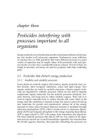
tigators [67,73,74]. Recently, detailed studies of samples from the FePRB at
the Y-12 site, Oak Ridge, TN (Fig. 3) have shown that the distribution and
speciation of uranium in the Fe
0
-bearing zone is complex, and that sampling
and characterization of these materials is challenging [75,76].
B. Removal by Transformation
To contrast with the term sequestration, we have chosen transformation to
represent chemical reactions that convert contaminants to distinct products.
The transformation of metals from one valence state to another was
included in the previous section because the effect of these transformations
is mainly to enhance sequestration. In contrast, there are a few nonmetal
inorganic contaminants that are transformed by Fe
0
to soluble but com-
paratively innocuous products, which are discussed below . Following that,
Figure 3 Scanning electron micrograph of an Fe
0
grain taken from an FePRB at
the Y-12 site at Oak Ridge, TN. The bright spot is mostly U, showing that these
deposits are localized on the Fe
0
surface. These deposits were associated with varying
amounts of Fe, S, Si, and Ca. Additional details on the analyses of these samples are
in Ref. 76.
Permeable Reactive Barriers 377
TM
Copyright © 2003 by Marcel Dekker, Inc. All Rights Reserved.
we review the reductive transformation of organic contaminants by Fe
0
,
with emphasis on the two most important pathways: dehalogenation of
chlorinated aliphatic or aromatic contaminants and reduction of nitro-
aromatic compounds.
1. Inorganic Transformations
The two most notable examples of reductive transformations by Fe
0
that
involve nonmetal inorganic compounds are reduction of nitrate [Eq. (4)] and
aqueous chlorine [Eq. (5)].
4Fe
0
þ NO
À
3
þ 10 H
þ
! 4Fe
2þ
þ NH
þ
4
þ 3H
2
O ð4Þ
Fe
0
þ 2 HOCl þ 2H
2
O ! Fe
2þ
þ 2H
þ
þ 2Cl
À
ð5Þ
The reduction of nitrate yields ammonia under most conditions [77–80], but
some have suggested that dinitrogen is formed [81]. Possible applications of
this process include not only the direct treatment of nitrate-con taminated
groundwater, but also the pretreatment of groundwater that is contami-
nated with both nitrate and radionuclides, in order to allow the development
of more strongly reducing biogeochem ical conditions (sulfidogenesis or
methanogenesis) that are necessary for microbially mediated immobilization
of uranium [75].
The reduction of aqueous chlorine (HOCl) to chloride by Fe
0
and other
ZVMs [Eq. (5)] has long been known as a major contributor to the decay of
residual chlorine disinfectant during distribution in drinking water supply
systems that contain metal pipes (e.g., Ref. 82). This reaction can, however,
be turned to advantage for the removal of excess residual chlorine, and a
variety of proprietary formulations of granular ZVMs are available com-
mercially for this purpose (e.g., KDF Fluid Treatment, Inc. Three Rivers,
MI). This application is sometimes called ‘‘dechlorination,’’ but should not
be confused with the dechlorination of orga nic contaminants, which is
discussed below.
Other nonmetal inorganic compounds that might be usefully trans-
formed by Fe
0
include perchlorate, sulfate, and cyanide. Although the
energetics for reduction of these compounds are all favorable, the kinetics
appear to be unfavorable in the absence of microbial mediation. In the case
of perchlorate, it has been reported that biodegradation can be inhibited by
Fe
0
[83]. This means that useful applications of these reactions will have to
wait until effective methods of catalyzing these reactions are discovered.
2. Dechlorination
Dehalogenation can occ ur by several reductive pathway s. The simplest
results in replacement of a C-bonded halogen atom with a hydrogen, and
Tratnyek et al.378
TM
Copyright © 2003 by Marcel Dekker, Inc. All Rights Reserved.
is known as hydrogenolysis or reductive dehalogenation .Forageneral
chlorinated aliphatic compound, RCl, hydrogenolysis by Fe
0
corresponds
to the overall reaction:
Fe
0
þ RCl þ H
þ
! Fe
2þ
þ RH þ Cl
À
ð6Þ
This reaction is the dominant dehalogenation pathway in reduction of
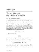
halogenated methanes [84] and haloacetic acids [85]. In Fig. 4, this re-
action is illustrated for perchloroethene (PCE), where complete dechlori-
nation by this pathway requires multiple hydrogenolysis steps. The relative
rates of these steps are a critical concern because they determine whether
Figure 4 Scheme showing the branching between hydrogenolysis (solid arrows),
reductive elimination (fine dashed arrows), and hydrogenation (course dashed
arrows) pathways to produce the major products of chlorinated ethene reduction by
ZVMs. (Adapted from Ref. 88.)
Permeable Reactive Barriers 379
TM
Copyright © 2003 by Marcel Dekker, Inc. All Rights Reserved.
persistent and hazardous intermediates (such as vinyl chloride, VC) will
accumulate [86,87].
In principle, aryl halo gens can also be subject to hydrogenolysis,
although this reaction is likely to be less facile than hydrogenolysis of most
alkyl halogens. In fact, the only confirmed example of hydrogeno lysi s
involving aryl halogens by Fe
0
under environmental conditions is for
pentachlorophenol, and the reaction was found similar in rate to literature
values for TCE [89]. In contrast, rapid hydrogenolysis of aryl halogens by
Fe
0
has been obtained under extreme conditions, such as in supercritical
water [90–92] or at high temperature [93]. These variations are not ame-
nable to use in a PRB, but are discussed along with related enhancements in
Sec. V.C.
The other major dehalogenation pathway involves elimination of
two halogens, leaving behind a pair of electrons that usually goes to form a
carbon-carbon double bond. Where the pathway involves halogens on adja-
cent carbons, it is known as vicinal dehalogenation or reductive b-elimination.
The fine dashed arrows in Fig. 4 illustrate this pro cess for PCE. Note that this
pathway can produce alkynes from vicinal dihaloalkenes [88,94,95], as well as
producing alkenes from vicinal dihaloalkanes [96,97].
In addition to the two major reductive pathways for dechlorination,
there are two additional reactions that have been observed: hydrogenation,
which involves addition of hydrogens across a C-C double or triple bond
[Eq. (9)] and dehydrohalogenation, which involves elimination of H
+
and X
À
and creation of a new C-C double bond [Eq. (10)]. Hydrogena tion has been
invoked to explain the distribution of products observed in several studies
involving chlorinated alkenes and Fe
0
[88], and is particularly important
where a noble metal like Pd is present to act as a catalyst (see Sec. III.B).
Note that we have written H
2
(surf) in Eq. (9) to represent all of the various
forms of surface-activated hydrogen, and do not mean to imply that the
reaction necessarily involves adsorbed diatomic molecular hydrogen. Dehy-
drohalogenation has not received much attention as a reaction that might
contribute to degradation of chlorinated ethenes by Fe
0
, even though it can
be base catalyzed [98], which might make it favored under the alkaline
conditions that can be created by corrosion of Fe
0
.
(7)
(8)
Tratnyek et al.380
TM
Copyright © 2003 by Marcel Dekker, Inc. All Rights Reserved.
3. Nitro and Azo Reduction
In general, reduction of aromatic nitro groups occu rs in three steps, via
nitroso and hydroxylamine intermediates, to the amine. For nitrobenzene and
simple substituted nitrobenzenes reacting with Fe
0
in batch model systems,
the intermediates have been detected in solution, but the dissolved amine
alone is usually sufficient for good mass balance [99–103]. Thus, the net
reaction is:
3Fe
0
þ ArNO
2
þ 6H
þ
! 3Fe
2þ
þ ArNH
2
þ 2H
2
O ð11Þ
Recently, research on nitro reduction by Fe
0
has been extended to
environmental contaminants with multiple nitro groups, such as TNT and
RDX [104–107]. As expected, batch experiments show that TNT and RDX
are rapidly reduced by Fe
0
to a complex mixture of products (Fig. 5). In
contrast, column experiments with TNT have shown a very high capacity to
Figure 5 Scheme showing branching among nitro reduction steps for TNT by
zero-valent metal. Triple arrows indicate that each step shown presumably proceeds
through three steps with nitroso and hydroxylamine intermediates. (Adapted from
similar figures for other reducing systems, including Refs. 109,110.)
(9)
(10)
Permeable Reactive Barriers 381
TM
Copyright © 2003 by Marcel Dekker, Inc. All Rights Reserved.
convert all products to triaminotoluene [108]. This result suggests that
earlier work, all of which appears to have been done in batch experiments,
may have led to unrepresentative conclusions regarding the formation of
soluble reduction products. Despite this simple FePRBs may be sufficient to
reach treatment goals for some explosives under real-field conditions.
In principle, the nitroso, hydroxylamine, and/or amine products of
nitro reduction might undergo coupling to form azoxy, azo, and/or hydrazo
dimers, but no evidence for these products has been found under the
conditions that have been studied to date. One reason that these dimers do
not accumulate may be that they are rapidly reduced by Fe
0
. In fact, Fe
0
reduces azo groups to amines [Eq. (12)] very rapidly [111–113], and this
reaction may prove to be useful in the remediation of wastewaters contami-
nated with azo dyes.
2Fe
0
þ ArN¼NAr þ 4H
þ
! 2Fe
2þ
þ 2 ArNH
2
ð12Þ
Like nitro and azo groups, the nitrosamine moiety is subject to
reduction by Fe
0
and is present in some important environmental contami-
nants. One such contaminant is N-nitrosodimethylamine (NDMA), which is
reduced by Fe
0
via a complex mechanism that gives the following overall
reaction [114,115]:
3Fe
0
þðCH
3
Þ
2
NN¼O þ 7H
þ
! 3Fe
2þ
þðCH
3
Þ
2
NH þ NH
þ
4
þ H
2
O
ð13Þ
NDMA is a potent carcinogen that not only occurs in groundwater con-
taminated with rocket fuels but can be formed from precursors that some-
times occur in groundwater and even drinking water [116]. Another
important nitrosamine that is reduced by Fe
0
is the explosive RDX [104–
106,117,118]. The products of this reaction are difficult to characterize, but
appear to be low molecular weight, polar, N-containing compounds, which
are likely to be analogous to the products formed from NDMA [Eq. (13)].
4. Other Organic Transformations
In principle, there are other organic functional groups that might be reduced
by Fe
0
under environmental conditions, including aldehyde, ketone, qui-
none, diamine, nitrile, oxime, imine, sulfoxide, and disulfide moieties [119–
121]. Recently, the reduction of quinonoid redox indicators by Fe
0
has been
explored in an educational context [122], but we are not aware of any
application of FePRBs for remediation of groun dwater contaminants that
contain these moieties . It is likely, however, that examples will emerge in the
future. In addition, it is to be expected that other types of transformations
will become accessible as ‘‘enhanced’’ and hybrid technologies involving
ZVMs become available. A few of these are discussed in Sec. V.C.
Tratnyek et al.382
TM
Copyright © 2003 by Marcel Dekker, Inc. All Rights Reserved.
To conclude this section, it is worth noting some of the chemistry
that is not expected in association with FePRBs. In general, any compound
that is easily oxidized will be a poor candidate for reduction. Such
compounds include saturated or aromatic hydrocarbons (including the
constituents of gasoline, coal tar, creosote, etc.), ethers and al cohols
(including MTBE, glycols, etc.), and phenols (e.g., cresols, various residues
from digestion lignin into paper pulp). At the same time, care should be
taken not to presume that a contaminant is transformed by reduction just
because it is found to be removed by contact with Fe
0
. This is illustrated by
recent reports that Fe
0
degrades the pesticides carbaryl [123] and benomyl
[124], both of which were attributed to reduction. However, these pesticides
do not contain any readily reducible functional grou ps. It is more likely
that Fe
0
degrades carbaryl by catalyzing alkaline hydrolysis of the phos-
phate ester moiety, and benomyl by catalyzing alkaline hydrolysis of the
amide moiety.
III. REACTIVE MEDIA AND THEIR PROPERTIES
There are two types of metals that are of interest as reactive media in PRBs:
(1) corrodable, base metals, which have equilibrium potentials for dissolu-
tion that are below the potential for reduction of water or any strongly
oxidizing solutes, and (2) noble, catalytic metals, which are not subject to
oxidative dissolution under environmental conditions but which participate
in reduction of solutes as catalysts. The corrodable, base metals (Fe, Zn, Sn,
etc.) are discussed in Sec. III.A, and the role of noble, catalytic metals (Pd,
Ni, etc.) in PRBs is discussed in Sec. III.B.
A. Iron and Other Corrodable Metals
Although the majority of interest in remediation applications of corrod-
able metals revolves around Fe
0
, other possibilities have been investigated,
including magnesium, tin, and zinc. The bulk of this work has used Zn
0
as a model system for comparison with Fe
0
(e.g., Refs. 95, 96, 125, and
126), but a few studies have surveyed a range of metals as possible alter-
natives to Fe
0
in environmental applications other than PRBs (e.g., Refs.
127 and 128).
1. Corrosion Chemistry
The corrosion reaction involving water [Eq. (14)] is slow but presumably
ubiquitous, whereas corrosion of Fe
0
by reaction with dissolved oxygen
[Eq. (15)] is rapid as long as O
2
is available.
Permeable Reactive Barriers 383
TM
Copyright © 2003 by Marcel Dekker, Inc. All Rights Reserved.
Fe
0
þ 2H
2
O ! Fe
2þ
þ H
2
þ 2OH
À
ð14Þ
2Fe
0
þ O
2
þ 2H
2
O ! 2Fe
2þ
þ 4OH
À
ð15Þ
The presence of a reducible contaminant in an Fe
0
-H
2
O system provides
another reaction [in addition to Eqs. (14)–(15)] that can con tribute to the
overall corrosion rate. This is exemplified in Eq. (6) for the hydrogenolysis of
a generic chlorinated hydrocarbon, Eq. (11) for nitro reduction, and Eq. (12)
for azo compounds.
For simplicity, we have written and balanced these equations for acidic
conditions, but the speciation of iron and some contaminants, as well as the
thermodynamic potentials for the associated redox half-reactions, will vary
with pH. The most efficient way to represent the effects of pH is in an Eh-pH
diagram, such as Fig. 6. This particular diagram shows that reduction of
three contaminants (CCl
4
, ArNO
2
, and Cr(VI)) by Fe
0
is thermodynamically
favorable over a wide range of pH, even though the speciation of the Fe(II)
Figure 6 Eh-pH diagram for the Fe
0
-H
2
O system where total dissolved
Fe=1
Â
10
À6
M, Fe
3
O
4
and Fe
2
O
3
are assumed to be the solubility limiting phases,
and [ox]=[red] for all redox active species. Other Eh–pH diagrams for Fe
0
-H
2
O-
contaminant systems can be found in Refs. 42, 84, and 129–131.
Tratnyek et al.384
TM
Copyright © 2003 by Marcel Dekker, Inc. All Rights Reserved.
that is form ed changes considerably. In contrast, reduction of U(VI) by Fe
0
switches from favorable to unfavorable where the pH increases above 8.
2. Common Types of Granular Iron
The Fe
0
that has been used for contaminant degradation includes con-
struction-grade material, used primarily in field applications, and reagent-
grade material, used primarily in laboratory studies. Construction-grade
granular iron is prepared from scrap ‘‘gray’’ or ductile cast iron by grinding
and sieving, and annealed under an oxidizing atmosphere. The resul ting
material usually has a thick outer layer of iron oxide, which sometimes
includes considerable amounts of inorganic carbon. Reagent-grade granular
iron is usually prepared by electrolytic precipitation, is then ground, sieved,
and sometimes annealed under a reducing atmosphere leaving a bright
metallic surface.
A great deal of empir ical testing has been done to determine which
types of iron are most reactive with a particular contaminant, but little of
this work has been reported in the peer-reviewed literature. A few studies
have summarized readily available properties of a significant range of iron
types [126,132], but these efforts fall far short of forming the basis for a
systematic understanding of the relative reactivity of granular metals. The
role of some physical properties of granular Fe
0
are well established, as
discussed in Sec. IV.A.1 and V.B.1, so these properties are summarized in
Table 2 for selected construction- and reagent-grade irons.
Table 2 Summary of Iron Properties
Supplier
s
(m
2
g
À1
)
a
s
(g cm
À3
)
b
b
(g cm
À3
)
c
Connelly iron aggregate (ETI CC-1004) 1.8 (2) 7.55 1.9
Peerless cast iron aggregate (ETI 8/50) 0.9F0.7(11) 7.39 2.2
Master builder 1.3F0.7 (14) 7.38 2.7
Fisher electrolytic 0.2F0.2 (9) 9.49 2.6
Fluka filings 0.03F0.06 (5) 8.58 3.8
a
Average of reported specific surface areas in m
2
per gram of Fe
0
as summarized in Ref. 80.
Statistics are based on independently reported values from the literature: uncertainties are one
standard deviation and the number of averaged values are given in parenthesis.
b
Specific density in grams per liter of Fe
0
volume [133]. For comparison, typical literature
values are 7.87 g cm
À3
for pure elemental iron, 7.2–7.3 for cast and malleable iron, and 4.9–5.3
for hematite [134].
c
Bulk density in grams per liter of total volume. Construction-grade Fe
0
can be prepared with
bulk densities from 1.4 to 3.5 g cm
À3
(90 to 220 lb ft
À3
), but currently available products are
about 2.4 g cm
À3
(150 lb ft
À3
) (David Carter, Peerless Metal Powders and Abrasives, personal
communication).
Permeable Reactive Barriers 385
TM
Copyright © 2003 by Marcel Dekker, Inc. All Rights Reserved.
B. Bimetallic Combinations
In addition to transformation by corrodable metals (such as Fe
0
and Zn
0
),
bimetallic combinations of a catalytic metal with a corrodable metal (such as
Pd/Fe or Ni/F e) have also been shown to transform a variety of contami-
nants. In most cases, rates of transformation by bimetallic combinations
have been significantly faster than those observed for iron metal alone
[26,96,135–139]. Not only have faster transformation rates been observed
with bimetallic combinations, but, in some cases, transformation of highly
recalcitrant compounds, such as polychlorinated biphenyls (PCBs), chlori-
nated phenols, and DDT has been achieved [24,140,141]. The mechan ism
responsible for the enhanced reactivity with bimetallic combinations is still
unclear; however, it has been suggested that electrochemical effects, catalytic
hydrogenation, or intercalation of H
2
may be responsible. A likely limitation
to the ful l-sc ale application of bimetallic combinations to groundwater
remediation is deactivation of the catalytic surface either by poisoning
(e.g., by sulfide) or by formation of thick oxide films [136,142,143].
IV. MICROSCALE PROCESSES
Almost everything that is known about the fundamental processes that are
responsible for contaminant removal by ZVMs has been derived from la-
boratory experiments done with bench-scale model systems. Of this work, the
majority has been done in batch reactors consisting of dilute slurries of Fe
0
particles suspended in small bottles. Batch experiments are simple to perform
and the results can be easy to analyze, but this method can be limiting, and
questions remain about how well it models conditions that are relevant to the
field. Recently, a few other small-scale laboratory model systems have been
described that offer greater control over key experimental variables, e.g.,
(rotating) iron disk electrodes [101,144], recirculating batch reactors [100],
and small columns operated in ‘‘ mis cible-displacement’’ mode [145]. Future
developments along these lines may greatly improve our understanding of the
fundamental chemistry that controls the performance of this technology.
Through the many studies that have now been done in well-controlled
model systems, a general conceptual model has emerged of the processes
controlling contaminant reduction on Fe
0
. Some of the key elements of this
model are summarized in Fig. 7, using a generic chlori nated hydrocarbon,
RX, as the model contaminant. First, RX must be conveyed to the stagnant
boundary layer at the oxide-water interface, then it must diffuse across the
boundary layer and form a complex with a reactive site either on or in the
oxide film (or directly on the Fe
0
through a defect in the oxide film [146]). Only
then can reduction occur (with electrons that ultimately come from the
Tratnyek et al.386
TM
Copyright © 2003 by Marcel Dekker, Inc. All Rights Reserved.
underlying Fe
0
), followed by desorption and diffusion of products away from
the surface.
A. Reaction at the Surface
1. Basic Kinetic Model
Most of the primary kinetic data that have been obtained from bench-scale
model systems suggest that reaction with Fe
0
is first order in the concen-
tration of solution phase contaminant, C. Thus, we can write the following
rate law in differential and integrated forms:
ÀdC=dt ¼ k
obs
C ð16Þ
lnðC
t
=C
0
Þ¼Àk
obs
t ð17Þ
where k
obs
is the pseudo-first-order rate constant. Experimental values of
k
obs
are routinely obtained from the slope of the regression line for ln(C
t
)
Figure 7 Schematic of the primary steps involved in dehalogenation of RX at Fe
0
-
oxide-H
2
O interface. Coarse dashed arrows represent mass transport between the
bulk solution and the particle surface, fine dashed arrows denote diffusion across the
stagnant boundary layer and surface complexation, and solid arrows show electron
transfer and bond rearrangement on the surface. (Adapted from Ref. 147.)
Permeable Reactive Barriers 387
TM
Copyright © 2003 by Marcel Dekker, Inc. All Rights Reserved.
or ln(C
t
/C
0
) vs. time. However, k
obs
will only be constant for a limited range
of experimental conditions, as it can be influenced by a host of system
properties. Two of the best characterized factors that influence k
obs
are
addressed below. Others, such as pH [84,148–150], are not discussed further
here because general models for their effects are not yet available.
Effect of Iron Concentration. Among the factors that influence k
obs
,
the effect of the amount of iron surface area that is accessible to the
contaminant has received the most attention. This effect is most often
described by a linear relationship:
k
obs
¼ k
SA
q
a
ð18Þ
where k
SA
is the specific reaction rate constant (L hr
À1
m
À2
) and q
a
is the
concentration of iron surface area (m
2
L
À1
of solution). Deviations from this
linear relationship have been reported [151–153], but their general
significance is not yet well established.
Data for k
SA
that were available as of November 1995 were summar-
ized in Refs. 86 and 132, but many more data have been reported since then.
Selected values of k
SA
are given in Table 3. In addition, quantitative
structure-activity relationships (QSARs) have been reported that may be
suitable for estimating values of k
SA
that have not been measured [87,88,
154–156].
The other term in Eq. (18), q
a
, can be calculated from:
q
a
¼ a
s
q
m
ð19Þ
where a
s
is the specific surface area (m
2
g
À1
) of a type of Fe
0
, usually
measured by BET gas adsorption, and q
m
is the mass concentration of Fe
0
Table 3 Selected Rate Constants for Reduction by Fe
0
Contaminant k
SA
a
(L hr
À1
m
À2
)
Carbon tetrachloride (CCl
4
) 1.2(F1.5)
Â
10
À1
(11)
b
;1.5
Â
10
À1
[157]
1,1,1-Trichloroethane (TCA) 1.1
Â
10
À2
[158]; 4.6
Â
10
À1
[96]
Trichloroethene (TCE) 3.9(F3.6)
Â
10
À4
(12)
b
; 3.3(F5.2)
Â
10
À4
(4)
c
;1.1
Â
10
À3
(2)
d
Vinyl chloride (VC) 5.0(+1.5)
Â
10
À5
(3)
b
;8.2
Â
10
À6
(5)
e
2,4,6-Trinitrotoluene (TNT) 5.0(F0.7)
Â
10
À2
(5)
f
a
For data that are derived from multiple independent experiments, the values in parentheses are the
standard deviation of the estimate, followed by the number of experiments.
b
Represents average of all published data as of November 1998 [86].
c
Average of values from four types of Fe
0
[69].
d
From Ref. 152.
e
From regression of k
obs
vs. q
m
[159].
f
Batch experiments done with Peerless iron [107].
Tratnyek et al.388
TM
Copyright © 2003 by Marcel Dekker, Inc. All Rights Reserved.
(grams of Fe per liter of solution volume). For batch studies, q
m
can be
calculated from
q
m
¼
M
Fe
V
H
2
O
¼
M
Fe
V
Tot
À M
Fe
=q
s
ð20Þ
where M
Fe
is the mass of Fe
0
(g), V
H
2
O
is the volume of solution (L), V
Tot
is
the total system volume (L), and q
s
is the density of the iron (g L
À1
occupied
by the Fe
0
).
Effect of Temperature. Several studies have shown that the kinetics of
contaminant reduction in batch experiments exhibit temperature depen-
dencies that conform to the Arrhenius equation [86,87,132,159,160]. Thus,
we can write the following expression relating the rate constants at T
1
and T
2
(in jK):
k
T
2
k
T
1
¼ e
ÀE
a
R
ðÞ
1
T
2
À
1
T
1
ð21Þ
where E
a
is the activation energy (kJ mol
À1
) and R is the gas constant (8.314 J
K
À1
mol
À1
). Adapting the approach taken in several previous publications
[49,161], we have used Eq. (21) to calculate correction factors (k
T2
/k
T1
)asa
function of groundwater temperature (T
2
), assuming a reference temperature
(T
1
)of23jC and appropriate values for E
a
. Five values of E
a
were selected to
generate Fig. 8: 55 kJ mol
À1
is nearly the value reported for CCl
4
reacting
with Fluka Fe
0
[144], 45 kJ mol
À1
is approximately the value reported for
vinyl chloride reacting with Fisher Fe
0
[159], 35 kJ mol
À1
approximates the
average E
a
for TCE reacting with both reagent- and construction-grade Fe
0
[160], 25 kJ mol
À1
represent regimes that are transitional between reaction
and mass transfer control [101], and 15 kJ mol
À1
represents kinetics that are
entirely limited by mass transfer [162]. In general terms, Fig. 8 shows that
reactions with Fe
0
will occur about half as rapidly in the field as they do at
temperatures that are typical of the laboratory. Note that there is less effect
of temperature on rates that are influenced by mass transport.
2. Multiprocess Kinetic Models
Competition for Reactive Sites. Recently, it has become widely
recognized that k
obs
can vary with the concentration of the contaminant.
In most cases, this effect has been attributed to saturation of reactive sites on
the Fe
0
surface. One kinetic model that has been used to describ e these data
is of the form:
À
dC
dt
¼
AC
B þ C
ð22Þ
Permeable Reactive Barriers 389
TM
Copyright © 2003 by Marcel Dekker, Inc. All Rights Reserved.
where A and B are constants [163]. Several studies have equated A and B
with V
m
and K
1/2
, by analogy to the Michaelis-Menten model for enzyme
kinetics [86,111,147]. Other studies have associated A with k
0
, the zero-order
rate constant observed when surface sites are fully satur ated [152], and
equated A/B with k
obs
when B>>C [107,152].
Site saturation kinetics can also be described with a kinetic mod el of
the form:
À
dC
dt
¼
DC
1 þ EC
ð23Þ
where D and E are constant s. Some studies have defined D and E in accord
with the Langmuir-Hinshelwood-Hougen-Watson (LHHW) model for sur-
face catalyzed reactions [88,125,164–166], whereas others have defined D
and E in terms derived from a surface complexation model [146]. Although
the Michaelis-Menten and LHHW models were derived for different systems
and conditions, the mathematical forms of these models [represented by
Eqs. (22) and (23)] are essentially equivalent. Consequently, it can be shown
that A=D/E and E=1/B.
Figure 8 Correction factors for the effect of temperature on the rate of reduction
by Fe
0
. Arrows indicate the reference temperature around which most laboratory
data are obtained (23jC), and a more representative temperature for groundwater
(15jC). Assuming E
a
c45 kJ mol
À1
for TCE [160], the corresponding correction
factor shown is 0.6 (i.e., rates will be slower in the field by 60%).
Tratnyek et al.390
TM
Copyright © 2003 by Marcel Dekker, Inc. All Rights Reserved.
In addition to competition by the contam inant for a limited supply of
reactive surface sites (intraspecies competition), there is evidence for com-
petition among different species for surface sites (interspecies competition).
Interspecies competition effects can arise between combinations of contam-
inants (e.g., Ref. 167) or between contaminants and other adsorbates
[102,146,147,159,168–170]. The kinetics that arise from interspecies compe-
tition have been modeled by adding appropriate terms to Eq. (22) or Eq.
(23). However, in most cases the parameterization of these models has been
rather preliminary and their sensitivity to uncertainties in these parameters
has not yet been thoroughly investigated.
Competition Among Reactive and Nonreactive Sites. In addition to
competition among different adsorbates for reactive sites, there is also
competition among different surface sites for adsorbat es. In principle, it is
easy to imagine that granular Fe
0
under environmental conditions might
present surface sites with energies that vary widely for adsorption and
reaction. To date, however, most of the available data have been explained
using a simple binary model that assumes surface sites are either reactive or
nonreactive (i.e., just adsorptive) and that the distribution of reactant
between these sites and the solution phase is in quasi-equilibrium.
Assuming that contaminant transformation rates are dependent on its
aqueous phase concentration and that most adsorption is to nonreactive
sites, then a kinetic model for transformation that accounts for sorption can
be written
ÀdC
T
=dt ¼ k
a
C
N
a
ð24Þ
where C
T
and C
a
are the total system and aqueous phase concentrations, k
a
is the rate constant for transform ation, and N is the reaction order [171].
This model has been applied for PCE and TCE [171,172] and cis- and trans-
1,2-dichloroethene [173]. The results are easily interpreted for PCE and
TCE, because both gave Nc1. However, the dichloroethenes both gave
N > 1, which suggests that Eq. (24) was not entirely adequate to describe the
system behavior.
A more complete and mechanistically explicit model has been
described that allows for competitive adsorption to reactive and nonreactive
sites on Fe
0
, as well as partiti oning to the headspace in closed experimental
systems and branching among parallel and sequential transformation path-
ways [174,175]. This model represents the distinction between reactive and
nonreactive sites by a parameter called the ‘‘fractional active site concen-
tration.’’ Simulations and sensitivity analysis performed with this model
have been explored extensively, but application of the model to experimen-
tal data has been limited to date.
Permeable Reactive Barriers 391
TM
Copyright © 2003 by Marcel Dekker, Inc. All Rights Reserved.
In cases where sorptive equilibrium is reached rapidly and transforma-
tion is much slower, the aqueous phase concentration of contaminant may
show a rapid initial decrease due to adsorption followed by a slower decline
due to transformation. Under these conditions, the kinetic model represented
by Eq. (16) is sufficient to describe the kinetics of transformation after the
initial data have been excluded. This approach has been taken for TCE [168],
vinyl chloride [176], and probab ly in many other studies where the exclusion
of initial rate data was not clearly documented.
Competition Among Parallel Reaction Pathways. The third form of
competition that complicates the kinetic description of contaminant
degradation by Fe
0
involves branching among parallel pathways (and/or
mechanisms) of transformation by the contaminant. Simple manifestations
of this effect—such as the transformation of TCE to form chloroacetylene,
trans-1,2-dichloroethene, cis-1,2-dichloroethene, or 1,1-dichloroethene from
TCE—can be described with ‘‘branching ratios’’ [132]. However, a more
general approach is to divide rate constants for reactant disappearance into
separate rate constants for each product formation pathway. Because first-
order rate constants are additive (for reactions occurring in parallel), we
can write the following for disappearance of TCE by the four pathways
noted above:
k
SA
¼ k
chloroacetylene
þ k
transÀ1;2ÀDCE
þ k
cisÀ1;2ÀDCE
þ k
1;1ÀDCE
ð25Þ
This approach has been taken for the reaction of chlorinated ethenes
with Zn
0
[125,165] and Fe
0
[88,166], resulting in separate rate constants for
all the reactions shown in Fig. 3. Care must be taken in using these
parameters in predictive modeling, however, as it is not yet known how
sensitive the relative values of these rate constants are to pH, thickness and
composition of the oxide film, etc. The same caution applies where the
approach represented by Eq. (25) is used to describe parallel mechanisms of
transformation. For example, it has recently been reported that several
experimental factors influence the relative contributions of dissociativ e
electron transfer, hydrogen atom transfer, and reductive elimination to
the dechlorination of carbon tetrachloride and TCE by Fe
0
[177].
B. Mass Transport to the Surface
The overall reaction occurring at an Fe
0
surface involves a series of steps
including: (1) mass transport to the reactive site, (2) chemical reaction at
the surface (e.g., sorption, electron transfer, etc.), (3) desorption, and (4)
mass transport to the bulk solution (recall Fig. 7). Any one of these
steps can limit the rate of contaminant removal by Fe
0
, so the observed
Tratnyek et al.392
TM
Copyright © 2003 by Marcel Dekker, Inc. All Rights Reserved.
rate (k
SA
) can be represented as a series of resistances due to transport
and reaction:
1
k
SA
¼
1
k
rxn
þ
1
k
mt
ð26Þ
where k
SA
is the overall surface area-normalized rate coefficient, k
mt
is
the mass transport coefficient, and k
rxn
is the first-order heterogeneous
reaction-rate coefficient. Mass transport resistances can be due to either
Figure 9 Comparison of previously reported values of k
SA
for reduction by Fe
0
with external mass transport coefficients estimated for batch, column, and rota-
ting disk electrode reactors. References for the overall rate coefficients are given
in Fig. 1 of Ref. 101. Mass transport coefficients were estimated for the batch
and column reactors based on empirical correlations discussed in Refs. 125 and
101. Mass transport coefficients for the RDE were calculated using the Levich
equation [178].
Permeable Reactive Barriers 393
TM
Copyright © 2003 by Marcel Dekker, Inc. All Rights Reserved.
external transport to the surface or internal transport through the oxide
layer (i.e., pore diffusion). Various forms of Eq. (26) have been used to
evaluate the role of external mass transport in contaminant reduction by
Fe
0
and Zn
0
[101,111,144,165].
Because rates of reduction by Fe
0
vary considerably over the range of
treatable contaminants, it is possible that there is a continuum of kinetic
regimes from purely reaction controlled, to intermediate, to purely mass
transport controlled. Fig. 9 illustrates the overlap of estimated mass trans-
port coefficients (k
mt
) and measured rate coefficients (k
SA
). The values of k
SA
are, in most cases, similar to or slower than the k
mt
values estimated for
batch and column reactors. The slower k
SA
values suggest that k
rxn
<k
mt
,
and therefore removal of most contaminants by Fe
0
should be reaction
limited or only slightly influenced by mass transport effects (i.e., an inter-
mediate kinetic regime).
Direct evidence of mass transport limitations for the more highly
reactive contaminants has been observed in RDE experiments and batch
and column reactors with Fe
0
. The measured k
rxn
of ArNO
2
reduction at a
bare Fe
0
electrode was about 10 times faster then the mass transport
coefficient estimated in a PRB [101]. In addition, evidence for mass trans-
port effects have been observed in both batch and column Fe
0
experiments
where rates of nitro aromatic [99,100] and azo dye [111] removal were
dependent on mixing speed or flow rate. The observed dependence of
reduction rate on mixing intensity and the similarity between rates of
surface reaction and mass transport suggest that mass transport may limit
removal rates of these highly reactive contaminants in FePRBs. An
interesting implication of these results is that for highly reactive compounds
(such as ArNO
2
and TNT), hydraulic designs that increase mass transport
rates (e.g., funnel-and-gate systems) may be useful for improving contam-
inant removal rates by FePRBs.
V. MACROSCALE PROCESSES
The microscale processes reviewed in the previous section may be sufficient
to describe the behavior of well-mixed model systems, but packed bed
systems (including columns, canisters, and PRBs) are also characterized by
processes that are manifest on length scales of meters and time scales of
hours. Progress toward understanding the macroscale processes associated
with FePRBs has been comparatively slow, in part because it has to be built
on a thorough understanding of the microscale processes occurring at the
metal-water interface, and the latter is still emerg ing. On the other hand, the
ultimate objective of FePRBs is remediation on the aquifer scale, so
Tratnyek et al.394
TM
Copyright © 2003 by Marcel Dekker, Inc. All Rights Reserved.
advancing our understanding of biogeochemical processes at the macro
scale is where many of the most significant advances can be expected as the
FePRB technology matures in the future.
A. Geochemical Gradients and Zones
Unlike well-mixed batch systems, columns and field conditions result in the
development of steep chemical gradients within the iron-bearing zone, at the
interfaces between the iron-bearing zone and the surrounding material, and
downgradient where the plume of treated water interacts with the native
aquifer material. Although some early work recognized that these gradients
could be significant (e.g., Refs. 179–181 ), further characterization of these
geochemical gradients has been needed at the field scale before their effects
on contaminant fate could be accurately assessed. Recently, considerable
progress on this topic has been made through integrated monitoring and
modeling studies associated with several field sites, including Moffett Field
in Mountain View, CA [182–184], the U.S. Coast Guard Support Center in
Elizabeth City, NC [185–188], and the Y-12 uranium processing plant in
Oak Ridge, TN [75,131,189,190].
The major geochemical gradients that have been observed associated
with FePRBs are summarized in Fig. 10. They involve (1) dissolved oxygen,
which is completely removed within a few millimeters of where groundwater
enters the iron-bearing zone, (2) dissolved H
2
, which rises over the width of
the iron-bearing zone to near saturation, (3) pH and dissolved Fe(II), both
of which usually rise rapidly inside the wall and then decline gradually in
the downgradient region, (4) dissolved CO
2
, which precipitates near the
upgradient interface as iron carbonates, (5) NO
3
À
, which is abiotically
reduced to ammonia, and (6) SO
4
2À
, which is reduced by anaerobic bacteria
to sulfide, much of which then precipitates as iron sulfides. Note that lateral
diffusion is very slow into the plume of treated groundwater, so reoxyge-
nation by this mechanism is expected to be mini mal and the anaerobic
plume may eventually extend a considerable distance downgradient from
an FePRB.
As a consequence of the gradients in groundwater geochemistry
described above, zones of authigenic precipitates develop along the flow
path of FePRBs and columns designed to simulate these conditions. A
considerable amount of research has been done on the iron oxides and
carbonates that accumulate near the upgradient interface because these
solids can cement grains and decrease porosity and thereby prevent
contaminate d groundwater f rom flowing through the treatment zone
[131,189,193–196]. The effect of these precipitates on overall rates of
contaminant reduction is not entirely clear, however, because most field
Permeable Reactive Barriers 395
TM
Copyright © 2003 by Marcel Dekker, Inc. All Rights Reserved.