Handbook Of Pollution Control And Waste Minimization - Chapter 8 pptx
Bạn đang xem bản rút gọn của tài liệu. Xem và tải ngay bản đầy đủ của tài liệu tại đây (289.71 KB, 10 trang )
8
Fundamentals of Heat Transfer
René Reyes Mazzoco
Universidad de las Américas–Puebla, Cholula, Mexico
1 HEAT TRANSFER MECHANISMS
1.1 Conduction
Conduction heat transfer is explained through the molecular motion in the solid’s
structure. Heat is transferred from one molecule to the adjacent molecule by
means of vibrational motion. This basic description points out that heat transfer
through a solid takes place entirely by conduction, and also states that it occurs
to a limited extent in liquids and gases because of their molecular mobility.
The mathematical formulation of conduction heat transfer was proposed by
Joseph Fourier while solving heat transfer problems in metal casting and tem-
plate. The first step for this formulation is the recognition that the amount of heat
transferred, q(W), from one point of a metal piece to another point of the same
medium (continuum) is proportional to the temperature difference between those
two points. The evaluation of the temperature difference through the derivative
in any direction (s) makes the measurement independent of any two specific
points and the distance between them:
q ∝
dT
ds
(1)
Copyright 2002 by Marcel Dekker, Inc. All Rights Reserved.
For most cases of conduction heat transfer in solids it is possible to change
the proportionality relation to an equality defining the proportionality constant
called thermal conductivity, k(W/m K). Thus, the calculation of the amount of
heat transferred per cross-sectional surface area, A(m
2
), is obtained from Fourier’s
first law:
q
a
=−k
dt
ds
(2)
1.1.1 Measurement of Thermal Conductivity
The thermal conductivity is a physical property characteristic of the medium and
is defined similarly for the three states of the matter. The expression for the
calculation of the amount of heat transferred by conduction is also used to define
the thermal conductivity, and one procedure for its measurement, that is, k, is
calculated after measuring the linear temperature difference between two points,
the amount of heat transferred, and the cross-sectional area associated with the
heat flow trajectory:
k =
q/a
−dT/ds
(3)
The procedure for calculating values of k is especially relevant for the
evaluation of this property in mixtures of contaminated media for which no
information is normally available. For this evaluation it is easier to calculate the
thermal diffusivity, α (where α = k/ρC
p
, m
2
/s) of the mixture while solving
Fourier’s second law in cylindrical coordinates:
∂T
∂t
=α
∂T
∂r
2
+
1
r
∂T
∂r
(4)
Thus, a cylinder with a substance of unknown thermal conductivity is
placed in a bath at constant temperature to obtain the initial and boundary
conditions associated with the solution of Eq. (4):
T(r, 0)
=
initial sample temperature
T(0, t)
=
measurement at the cylinder’s center
T(R, t)
=
constant bath temperature
The value of α can be obtained from the solution of Eq. (4) with
these boundary conditions. The values of the density, ρ, and the constant-pressure
heat capacity, C
p
, are normally available in the literature, or are measured
experimentally.
Thermal conductivity prediction models are available for gases and liquids
in several references (e.g., Ref. 1).
Copyright 2002 by Marcel Dekker, Inc. All Rights Reserved.
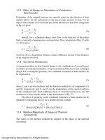
1.1.2 Effect of Shape on Calculation of Conduction
Heat Transfer
Evaluation of the integral between two specific points in the direction of heat
transfer allows for the calculation of the macroscopic amount of heat. For an
object with constant cross-sectional area in the direction of heat flow, integration
of Eq. (2) gives:
q
A
= k
T
1
− T
2
s
2
− s
1
(5)
Instead, for a cylindrical object, heat flow in the direction of the radius
finds a constantly changing cross-sectional area. Thus, integration of Eq. (2) with
A = 2πrL gives
q =
T
1
− T
2
ln(r
2
/r
1
)/2πkl
(6)
which involves a logarithmic distance (radius) difference instead of the thickness
of the medium involved.
1.1.3 Combined Resistances
A common problem in heat transfer design is the combination of several layers
of solid to provide heat insulation, or layers of solid and fluid as in heat exchanger
design. For a rectangular geometry, two combined resistances to heat transfer can
be expressed as
q
A
=
T
1
− T
2
(L
1
/k
1
)+(L
2
/k
2
)
(7)
where L and k are the thickness and the thermal conductivity of components (1)
and (2), respectively, and T
1
and T
2
are the temperatures at the external surfaces
of the combined wall. Each additional layer of material increases by one the
resistances to heat transfer added in the denominator of Eq. (7).
The effect of geometry on the combined resistances to heat transfer can be
obtained by integrating Eq. (2) for a double-layered cylinder:
q =
T
2
− T
1
[ln(r
2
/r
1
)/(2πk
1
L)] + [ln(r
3
/r
2)
/(2πk
2
L)]
(8)
1.1.4 Relative Magnitude of Values of Thermal
Conductivity
The values of the thermal conductivity depend on the phase of the material
considered:
Copyright 2002 by Marcel Dekker, Inc. All Rights Reserved.
k
gas
< k
liquid
< k
solid
Thus, solid materials are good heat conductors, while for heat insulation trapped
gases are the best option. Good electric conductor metals are the best selection
for heat conductors. The design of heat insulation follows the criteria for air
entrapment in fabrics or ceramics that could be resistant to high temperatures.
1.2 Convection
Heat convection is described as heat transport in fluid eddies promoted by the
flow derived from a mechanical device, a pump or fan (forced convection), or a
density difference (natural convection). The mechanism is associated with the
definition of the convective heat transfer coefficient, h(W/m
2
˚C):
h =
q
A(T
2
− T
1)
(9)
As the turbulent flow process carrying the heat cannot be fully described,
the temperature difference is considered at two points (1) and (2) in the direction
of heat transfer. It is not possible to describe this process through a differential
equation, and Eq. (9) is a definition for h that is related to the specific geometry
associated to the surface area, A, and the flow conditions.
The convective heat transfer coefficient can be calculated for design
purposes from experimental information gathered in the open literature. Experi-
ments have been carried out under geometry, flow range, and similar thermo-
physical properties conditions that can be encountered in process applications.
The information has been grouped in terms of flow conditions and thermophysical
properties involved.
Flow conditions are described through the Reynolds number (Re) for forced
convection. The Reynolds number relates the momentum convection associated
to the flow velocity, v, to the momentum diffusivity associated to ν, the kinematic
viscosity (ν = µ/ρ), µ is Newtonian viscosity (kg/ms). At low Reynolds numbers,
implying low flow velocity, momentum diffusivity dominates, and the fluid
displacement is in the laminar flow condition. When the flow velocity is high
relative to the kinematic viscosity, the Reynolds number is high, indicating
turbulent flow conditions.
Re =
Lν
v
(10)
L is the flow characteristic length; for internal flow in circular pipes, L is the
internal diameter.
The Grashof number (Gr) describes flow conditions for natural convection
and is used instead of the Reynolds number.
Copyright 2002 by Marcel Dekker, Inc. All Rights Reserved.
Gr =
gβ(T
w
− T
infinity
)L
3
v
2
(11)
Here g is the acceleration of gravity, T
w
is the solid wall temperature, T
infinity
is
the fluid bulk temperature, L is the heat transfer characteristic length, and β is the
volume coefficient of expansion:
β=
(ρ
infinity
−ρ)
ρ(T − T
infinity
)
(12)
ρ
infinity
is the fluid bulk density.
In natural and forced convection, the Prandtl number describes the influ-
ence of thermophysical properties in the calculation of the convective heat
transfer coefficient, normally to the
1
⁄
3
power.
Pr =
v
α
=
C
p
µ
k
(13)
The Nusselt number, Nu, is the ratio of heat convection to diffusion
associated to the heat transfer characteristic length, L:
Nu =
hL
k
(14)
From the exact analysis of the boundary layer between the fluid and the
solid wall transferring heat, the correlation in forced convection among Nusselt,
Reynolds, and Prandtl numbers is
Nu = 0.664 Re
1/2
Pr
1/3
(15)
This theoretical correlation has very limited application, and the depend-
ence of these dimensionless numbers on the geometry makes experimentation
necessary to calculate correlations for each geometry. The correlation results are
normally reported with the same mathematical formulation:
Nu = c
0
Re
n
Pr
m
(16)
For natural convection, the analysis of the boundary layer provides the
correlation of the important dimensionless numbers:
Nu = C(Gr Pr)
m
(17)
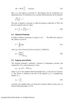
1.3 Radiation
For practical conditions, radiation emitted (or received) by surface is calculated
from an equation that involves the effect of the area, A
12
, the emissivity, ε
1
, of
the emitting surface involved, and a view factor, F
12
, that describes the effect
Copyright 2002 by Marcel Dekker, Inc. All Rights Reserved.
of the relative positions of the two surfaces involved on the amount of radiation
exchanged. The formulation of the exchanged radiation is
q =σε
1
A
12
F
12
(T
1
4
− T
2
4
) (18)
All practical terms in Eq. (18) are measured experimentally and are reported in
several references (e.g., Ref. 2)
2 HEAT ACCUMULATION
Heat accumulation is described through the heat capacity. The specific property
normally used to achieve this calculation is the constant-pressure heat capacity,
C
p
(J/kg ˚C). The total amount of material that stores heat should be expressed in
the mass or molar terms used for the C
p
. The heat stored is then a function of the
temperature change in the total mass considered:
C
p
=
q
m(dT/dt)
(19)
The temperature variation with time allows the evaluation of the heat flow
accumulated.
2.1 Sensible Heat
The variation of the temperature in a fluid medium defines sensible heat. The
calculation of the amount of sensible heat is obtained from Eq. (19). The heat
capacity should correlate the fluid and phase considered.
2.2 Latent Heat
The process where a change of phase takes place requires the addition of latent
heat. The latent heat is used to change phase in a fluid without a change in the
medium temperature. The evaluation of the latent heat is necessary to measure
the amount of heat required for phase change. Latent heat values and prediction
correlations are available in Ref. 1.
3 EXPERIMENTAL MEASUREMENT AND PREDICTION OF
HEAT TRANSFER THERMOPHYSICAL PROPERTIES
3.1 Constant-Pressure Heat Capacity, C
p
Measurement of the C
p
requires the evaluation of temperature change in a fixed
mass of material due to a heat flow from the surroundings according to Eq. (19).
Copyright 2002 by Marcel Dekker, Inc. All Rights Reserved.
3.2 Thermal Conductivity, k
For the measurement of k, Fourier’s first law is normally used to define the
parameters involved in the evaluation. The heat flux in Eq. (2) is determined
from the heat flow and the body geometry while the temperature gradient is
measured directly.
3.3 Convective Heat Transfer, h
The convective heat transfer coefficient is experimental measured of forced- and
natural-convection conditions. h is part of Nu, while flow conditions are repre-
sented by Re or Gr, and the thermophysical properties form Pr.
Normally, the values of h are obtained from reported correlations. If it is
necessary to evaluate h for conditions not previously studied, the information is
gathered and analyzed according to Eq. (16) or (17).
3.4 Thermophysical Properties of Mixtures in
Pollution Control
Mixtures of contaminated media normally require the experimental evaluation of
the thermophysical properties. In some cases, due to nonavailability of the
experimental data, correlations for calculating the thermophysical properties
are limited.
4 HEAT TRANSFER DESIGN
Process efficiency is defined at the design stage. Design algorithms for heat
transfer equipment can be found in several classic references (e.g., Ref. 3) and
are still used for designing heat transfer equipment. Several software options are
also available for efficient heat transfer equipment design; software the descrip-
tion can be obtained from demos downloaded from an Internet search (any search
engine) on “Heat Exchangers.”
The basic equation for heat exchange design is
q = U
o
A
o
∆T
LM
F (20)
where U
o
is the overall heat transfer coefficient and includes all the heat transfer
conductances around the solid wall transferring heat. For a flat wall transferring
heat,
U
o
=
1
1/h
inside
+ G/k + 1/h
outside
(21)
where h
inside
is the inside convective heat transfer coefficient, G is the wall
thickness, and h
outside
is the outside heat transfer coefficient.
Copyright 2002 by Marcel Dekker, Inc. All Rights Reserved.
The driving force for heat transfer in a heat exchanger is the logarithmic
mean temperature difference:
∆T
LM
F =
[T
outlet
− t
inlet
)−(T
inlet
− t
outlet
)]F
ln[(T
outlet
− t
inlet
)/(T
inlet
− t
outlet
)]
(22)
T is the hot fluid temperature, t is the cold fluid temperature, and F is the
efficiency factor adapted for each configuration of shell and tube, plate exchang-
ers, and direct-contact heat exchangers (4).
From the calculation of the amount of heat transferred, including the
temperature changes involved and the overall heat transfer conductance, the area
for heat exchange is determined. Several heat transfer equipment can be used to
accomplish the heat exchange between the media in a given process condition.
4.1 Heat Transfer Design and Good Engineering Practices
Design defines the efficiency of the operation of a process. Once the optimized
design is utilized, it is necessary to maintain good engineering practices. These
practices should include pollution control and waste minimization.
Heat transfer equipment is subjected to fouling and corrosion, which
are among the major hurdles for the operation. Fouling increases heat transfer
resistance and waste of energy. Good engineering practices include the use of
fouling suppresants in heat transfer fluids and periodic cleaning of the ex-
changer walls.
For water as the cooling or heating medium in industrial operations there
are several standard techniques for keeping fouling low. Water in cooling-water
circuits has to be treated to keep salts and dirt content low. Common treatments
include the addition of coagulants for sedimentation of some salts and particles;
addition of biocides, to prevent microbial growth that is another source of fouling;
and the addition hardness suppresants such as polyphosphates; among others.
Although the materials used in heat transfer fluids treatment are a source of solid
waste, handling its final deposition should follow normal procedures. Fouling
prevention is not considered a polluting operation. Fouling prevention by-products
can be integrated to cement kiln operations when feasible, in order to eliminate
waste generation.
Corrosion protection of heat transfer surfaces is a suggested practice
for pollution control and waste minimization. In order to prevent corrosion,
begin with the analysis of the appropriate combination of materials and flu-
ids. For the operating equipment, passive and active cathodic protection are
recommended.
Copyright 2002 by Marcel Dekker, Inc. All Rights Reserved.
4.2 Innovations for Efficient Heat Use
Efficient energy use is a direct way to reduce pollution and minimize wastes from
industrial sources. The ongoing research in energy efficiency and resulting
innovations highlight the intensity of scientific activity in this field.
New approaches to increase heat transfer efficiency include the following.
1. Fluidized bed combustion is the choice for eliminating solids in solid-
waste management schemes. In general, direct contact between the
materials increases heat transfer efficiency. Direct contact reduces the
heat transfer resistances due to the wall in conventional equipment, and
increases the convective heat transfer coefficients due to the higher
contact velocities between the materials and fluids.
2. To increase the efficiency in steam generation, direct-contact heat
exchangers make use of residual heat from combustion gases to preheat
the feed streams to the boiler. Thermal recovery is a possibility from
direct-contact heat exchangers and heat pumps. Rotary drums recover
heat from a residual discharge in an steam generator and transport it to
preheat the inlet streams to the generator.
3. Heat pipes are a promising technology for increasing residual heat
usage as heat pumps. Heat pipes use capillary pressure as the driving
force for condensing and evaporating the working fluid, thus elim-
inating the necessity for pump and compressor in the power cycle. The
understanding of heat pipe operation is related to the evaluation of con-
vective heat transfer coefficients for change-of-phase heat transfer.
4. Plate heat exchangers are now available for almost any process condi-
tion, including high-pressure and corrosivity conditions. Enhanced heat
transfer surfaces improve energy management, reducing wastes. Im-
proved surfaces increase the convective heat transfer coefficients for
heating–cooling operations, and change-of-phase heat transfer.
5. Co-generation in chemical and petrochemical processes makes use of
the process integration gained from the use of simulation and pinch-
point techniques to increase energy usage.
5 CONCLUSIONS
The understanding of heat transfer fundamentals is a basic step toward the
proposition of improved industrial solutions in terms of energy wastes minimization.
Clear fundamental concepts make the use of design software straight-
forward. This is the approach to equipment design that produces the best results
for waste minimization.
Copyright 2002 by Marcel Dekker, Inc. All Rights Reserved.
Heat transfer innovations are improving energy handling in industrial
processes, reducing pollution and wastes. This research field is active in funda-
mentals such as enhanced heat transfer or heat pipe development.
REFERENCES
1. R. C. Reid, J. M. Prausnitz and B. E. Poling, The Properties of Gases and Liquids, 4th
ed. New York: McGraw-Hill, 1987.
2. J. P. Holman, Heat Transfer, 8th ed. New York: McGraw-Hill, 1997.
3. D. Q. Kern, Process Heat Transfer. New York: McGraw-Hill, 1950.
4. O. Levenspiel, Engineering Flow and Heat Exchange, 2nd ed. New York: Plenum
Press, 1992.
Copyright 2002 by Marcel Dekker, Inc. All Rights Reserved.