Material Science_ Vol 1 of 2 - US DOE (1993) WW Part 5 docx
Bạn đang xem bản rút gọn của tài liệu. Xem và tải ngay bản đầy đủ của tài liệu tại đây (314.28 KB, 8 trang )
Structure of Metals DOE-HDBK-1017/1-93 ALLOYS
ALLOYS
Most of the materials used in structural engineering or component fabrication are
metals. Alloying is a common practice because metallic bonds allow joining of
different types of metals.
EO 1.10 DEFINE the term alloy.
EO 1.11 DESCRIBE an alloy as to the three possible microstructures
and the two general characteristics as compared to pure metals.
EO 1.12 IDENTIFY the two desirable properties of type 304 stainless
steel.
An alloy is a mixture of two or more materials, at least one of which is a metal. Alloys can
have a microstructure consisting of solid solutions, where secondary atoms are introduced as
substitutionals or interstitials (discussed further in the next chapter and Module 5, Plant
Materials) in a crystal lattice. An alloy might also be a crystal with a metallic compound at each
lattice point. In addition, alloys may be composed of secondary crystals imbedded in a primary
polycrystalline matrix. This type of alloy is called a composite (although the term "composite"
does not necessarily imply that the component materials are metals). Module 2, Properties of
Metals, discusses how different elements change the physical properties of a metal.
Alloys are usually stronger than pure metals, although they generally offer reduced electrical and
thermal conductivity. Strength is the most important criterion by which many structural
materials are judged. Therefore, alloys are used for engineering construction. Steel, probably
the most common structural metal, is a good example of an alloy. It is an alloy of iron and
carbon, with other elements to give it certain desirable properties.
As mentioned in the previous chapter, it is sometimes possible for a material to be composed
of several solid phases. The strengths of these materials are enhanced by allowing a solid
structure to become a form composed of two interspersed phases. When the material in question
is an alloy, it is possible to quench (discussed in more detail in Module 2, Properties of Metals)
the metal from a molten state to form the interspersed phases. The type and rate of quenching
determines the final solid structure and, therefore, its properties.
Rev. 0 Page 15 MS-01
Structure of Metals DOE-HDBK-1017/1-93 IMPERFECTIONS IN METALS
Type 304 stainless steel (containing 18%-20% chromium and 8%-10.5% nickel) is used in the
tritium production reactor tanks, process water piping, and original process heat exchangers.
This alloy resists most types of corrosion.
The wide variety of structures, systems, and components found in DOE nuclear facilities are
made from many different types of materials. Many of the materials are alloys with a base
metal of iron, nickel, or zirconium. The selection of a material for a specific application is
based on many factors including the temperature and pressure that the material will be exposed
to, the materials resistance to specific types of corrosion, the materials toughness and hardness,
and other material properties.
One material that has wide application in the systems of DOE facilities is stainless steel. There
are nearly 40 standard types of stainless steel and many other specialized types under various
trade names. Through the modification of the kinds and quantities of alloying elements, the steel
can be adapted to specific applications. Stainless steels are classified as austenitic or ferritic
based on their lattice structure. Austenitic stainless steels, including 304 and 316, have a face-
centered cubic structure of iron atoms with the carbon in interstitial solid solution. Ferritic
stainless steels, including type 405, have a body-centered cubic iron lattice and contain no nickel.
Ferritic steels are easier to weld and fabricate and are less susceptible to stress corrosion
cracking than austenitic stainless steels. They have only moderate resistance to other types of
chemical attack.
Other metals that have specific applications in some DOE nuclear facilities are inconel and
zircaloy. The composition of these metals and various types of stainless steel are listed in
Table 2 below.
%Fe %C
Max
%Cr %Ni %Mo %Mn
Max
%Si
Max
%Zr
304 Stainless Steel Bal. 0.08 19 10 2 1
304L Stainless Steel Bal. 0.03 18 8 2 1
316 Stainless Steel Bal. 0.08 17 12 2.5 2 1
316L Stainless Steel Bal. 0.03 17 12 2.5 2
405 Stainless Steel Bal. 0.08 13 1 1
Inconel 8 0.15 15 Bal. 1 0.5
Zircaloy-4 0.21 0.1 Bal.
MS-01 Page 16 Rev. 0
Structure of Metals DOE-HDBK-1017/1-93 ALLOYS
The important information in this chapter is summarized below.
An alloy is a mixture of two or more materials, at least one of which is a metal.
Alloy microstructures
Solid solutions, where secondary atoms introduced as substitutionals or
interstitials in a crystal lattice.
Crystal with metallic bonds
Composites, where secondary crystals are imbedded in a primary
polycrystalline matrix.
Alloys are usually stronger than pure metals although alloys generally have
reduced electrical and thermal conductivities than pure metals.
The two desirable properties of type 304 stainless steel are corrosion resistance
and high toughness.
Rev. 0 Page 17 MS-01
IMPERFECTIONS IN METALS DOE-HDBK-1017/1-93 Structure of Metals
IMPERFECTIONS IN METALS
The discussion of order in microstructures in the previous chapters assumed
idealized microstructures. In reality, materials are not composed of perfect
crystals, nor are they free of impurities that alter their properties. Even
amorphous solids have imperfections and impurities that change their structure.
EO 1.13 IDENTIFY the three types of microscopic imperfections found
in crystalline structures.
EO 1.14 STATE how slip occurs in crystals.
EO 1.15 IDENTIFY the four types of bulk defects.
Microscopic imperfections are generally classified as either point, line, or interfacial
imperfections.
1. Point imperfections have atomic dimensions.
2. Line imperfections or dislocations are generally many atoms in length.
3. Interfacial imperfections are larger than line defects and occur over a two-
dimensional area.
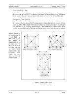
Point imperfections in crystals can be divided into three main defect categories. They
are illustrated in Figure 7.
1. Vacancy defects result from a missing atom in a lattice position. The
vacancy type of defect can result from imperfect packing during the
crystallization process, or it may be due to increased thermal vibrations
of the atoms brought about by elevated temperature.
2. Substitutional defects result from an impurity present at a lattice position.
3. Interstitial defects result from an impurity located at an interstitial site or
one of the lattice atoms being in an interstitial position instead of being
at its lattice position. Interstitial refers to locations between atoms in a
lattice structure.
MS-01 Page 18 Rev. 0
Structure of Metals DOE-HDBK-1017/1-93 IMPERFECTIONS IN METALS
Interstitial impurities called network modifiers act as point defects in
amorphous solids. The presence of point defects can enhance or lessen
the value of a material for engineering construction depending upon the
intended use.
Figure 7 Point Defects
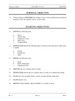
Figure 8 Line Defects (Dislocations)
Line imperfections are called dislocations
and occur in crystalline materials only.
Dislocations can be an edge type, screw
type, or mixed type, depending on how
they distort the lattice, as shown in
Figure 8. It is important to note that
dislocations cannot end inside a crystal.
They must end at a crystal edge or other
dislocation, or they must close back on
themselves.
Edge dislocations consist of an extra row
or plane of atoms in the crystal structure.
The imperfection may extend in a straight
line all the way through the crystal or it
may follow an irregular path. It may
also be short, extending only a small
distance into the crystal causing a slip of
one atomic distance along the glide plane
(direction the edge imperfection is
moving).
Rev. 0 Page 19 MS-01
IMPERFECTIONS IN METALS DOE-HDBK-1017/1-93 Structure of Metals
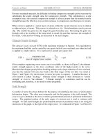
The slip occurs when the crystal is subjected to a stress, and the dislocation moves
through the crystal until it reaches the edge or is arrested by another dislocation, as
shown in Figure 9. Position 1 shows a normal crystal structure. Position 2 shows a force
applied from the left side and a counterforce applied from the right side. Positions 3 to
5 show how the structure is slipping. Position 6 shows the final deformed crystal
structure. The slip of one active plane is ordinarily on the order of 1000 atomic
distances and, to produce yielding, slip on many planes is required.
Screw dislocations can be produced by a tearing of the crystal parallel to the slip
Figure 9 Slips
direction. If a screw dislocation is followed all the way around a complete circuit, it
would show a slip pattern similar to that of a screw thread. The pattern may be either
left or right handed. This requires that some of the atomic bonds are re-formed
continuously so that the crystal has almost the same form after yielding that it had
before.
The orientation of dislocations may vary from pure edge to pure screw. At some
intermediate point, they may possess both edge and screw characteristics. The
importance of dislocations is based on the ease at which they can move through crystals.
MS-01 Page 20 Rev. 0
Structure of Metals DOE-HDBK-1017/1-93 IMPERFECTIONS IN METALS
Interfacial imperfections exist at an angle between any two faces of a crystal or crystal
form. These imperfections are found at free surfaces, domain boundaries, grain
boundaries, or interphase boundaries. Free surfaces are interfaces between gases and
solids. Domain boundaries refer to interfaces where electronic structures are different
on either side causing each side to act differently although the same atomic arrangement
exists on both sides. Grain boundaries exist between crystals of similar lattice structure
that possess different spacial orientations. Polycrystalline materials are made up of many
grains which are separated by distances typically of several atomic diameters. Finally,
interphase boundaries exist between the regions where materials exist in different phases
(i.e., BCC next to FCC structures).
Three-dimensional macroscopic defects are called bulk defects. They generally occur on a much
larger scale than the microscopic defects. These macroscopic defects generally are introduced
into a material during refinement from its raw state or during fabrication processes.
The most common bulk defect arises from foreign particles being included in the prime material.
These second-phase particles, called inclusions, are seldom wanted because they significantly
alter the structural properties. An example of an inclusion may be oxide particles in a pure
metal or a bit of clay in a glass structure.
Other bulk defects include gas pockets or shrinking cavities found generally in castings. These
spaces weaken the material and are therefore guarded against during fabrication. The working
and forging of metals can cause cracks that act as stress concentrators and weaken the material.
Any welding or joining defects may also be classified as bulk defects.
Rev. 0 Page 21 MS-01
IMPERFECTIONS IN METALS DOE-HDBK-1017/1-93 Structure of Metals
The important information in this chapter is summarized below.
Microscopic Imperfections
Point imperfections are in the size range of individual atoms.
Line (dislocation) imperfections are generally many atoms in length. Line
imperfections can be of the edge type, screw type, or mixed type, depending on
lattice distortion. Line imperfections cannot end inside a crystal; they must end
at crystal edge or other dislocation, or close back on themselves.
Interfacial imperfections are larger than line imperfections and occur over a two
dimensional area. Interfacial imperfections exist at free surfaces, domain
boundaries, grain boundaries, or interphase boundaries.
Slip occurs when a crystal is subjected to stress and the dislocations march
through the crystal until they reach the edge or are arrested by another
dislocation.
Macroscopic Defects
Bulk defects are three dimensional defects.
Foreign particles included in the prime material (inclusions) are most
common bulk defect
Gas pockets
Shrinking cavities
Welding or joining defects
MS-01 Page 22 Rev. 0