Material Science_ Vol 2 of 2 - US DOE (1993) WW part 3 docx
Bạn đang xem bản rút gọn của tài liệu. Xem và tải ngay bản đầy đủ của tài liệu tại đây (53.33 KB, 8 trang )
Thermal Shock DOE-HDBK-1017/2-93 OBJECTIVES
TERMINAL OBJECTIVE
1.0 Without references, DESCRIBE the importance of minimizing thermal shock (stress).
ENABLING OBJECTIVES
1.1 IDENTIFY the two stresses that are the result of thermal shock (stress) to plant materials.
1.2 STATE the two causes of thermal shock.
1.3 Given the material’s coefficient of Linear Thermal Expansion, CALCULATE the thermal
shock (stress) on a material using Hooke’s Law.
1.4 DESCRIBE why thermal shock is a major concern in reactor systems when rapidly
heating or cooling a thick-walled vessel.
1.5 LIST the three operational limits that are specifically intended to reduce the severity of
thermal shock.
1.6 DEFINE the term pressurized thermal shock.
1.7 STATE how the pressure in a closed system effects the severity of thermal shock.
1.8 LIST the four plant transients that have the greatest potential for causing thermal shock.
1.9 STATE the three locations in a reactor system that are of primary concern for thermal
shock.
Rev. 0 Page v MS-03
DOE-HDBK-1017/2-93 Thermal Shock
Intentionally Left Blank.
MS-03 Page vi Rev. 0
Thermal Shock DOE-HDBK-1017/2-93 THERMAL STRESS
THERMAL STRESS
Thermal stresses arise in materials when they are heated or cooled. Thermal
stresses effect the operation of facilities, both because of the large components
subject to stress and because they are effected by the way in which the plant is
operated. This chapter describes the concerns associated with thermal stress.
EO 1.1 IDENTIFY the two stresses that are the result of thermal shock
(stress) to plant materials.
EO 1.2 STATE the two causes of thermal stresses.
EO 1.3 Given the material's coefficient of Linear Thermal Expansion,
CALCULATE the thermal stress on a material using
Hooke's Law.
EO 1.4 DESCRIBE why thermal stress is a major concern in reactor
systems when rapidly heating or cooling a thick-walled vessel.
EO 1.5 LIST the three operational limits that are specifically intended
to reduce the severity of thermal shock.
Thermal Shock
Thermal shock (stress) can lead to excessive thermal gradients on materials, which lead to
excessive stresses. These stresses can be comprised of tensile stress, which is stress arising from
forces acting in opposite directions tending to pull a material apart, and compressive stress, which
is stress arising from forces acting in opposite directions tending to push a material together.
These stresses, cyclic in nature, can lead to fatigue failure of the materials.
Thermal shock is caused by nonuniform heating or cooling of a uniform material, or uniform
heating of nonuniform materials. Suppose a body is heated and constrained so that it cannot
expand. When the temperature of the material increases, the increased activity of the molecules
causes them to press against the constraining boundaries, thus setting up thermal stresses.
Rev. 0 Page 1 MS-03
THERMAL STRESS DOE-HDBK-1017/2-93 Thermal Shock
If the material is not constrained, it expands, and one or more of its dimensions increases. The
thermal expansion coefficient (α) relates the fractional change in length , called thermal
∆
strain, to the change in temperature per degree ∆T.
α = (3-1)
∆
∆
= α∆T (3-2)
∆
where:
l = length (in.)
∆l = change in length (in.)
α = linear thermal expansion coefficient (°F
-1
)
∆T = change in temperature (°F)
Table 1 lists the coefficients of linear thermal expansion for several commonly-encountered
materials.
TABLE 1
Coefficients of Linear Thermal Expansion
Material Coefficients of Linear Thermal Expansion (°F
-1
)
Carbon Steel 5.8 x 10
-6
Stainless Steel 9.6 x 10
-6
Aluminum 13.3 x 10
-6
Copper 9.3 x 10
-6
Lead 16.3 x 10
-6
MS-03 Page 2 Rev. 0
Thermal Shock DOE-HDBK-1017/2-93 THERMAL STRESS
In the simple case where two ends of a material are strictly constrained, the thermal stress can
be calculated using Hooke's Law by equating values of from Equations (3-1), (3-2), and
∆
(3-3).
E = = (3-3)
∆
or
= (3-4)
∆
α∆T = (3-5)
F/A = Eα∆T
where:
F/A = thermal stress (psi)
E = modulus of elasticity (psi)
α = linear thermal expansion coefficient (°F
-1
)
∆T = change in temperature (°F)
Example: Given a carbon steel bar constrained at both ends, what is the thermal stress when
heated from 60°F to 540°F?
Solution:
α = 5.8 x 10
-6
/°F (from Table 1)
E = 3.0 x 10
7
lb/in.
2
(from Table 1, Module 2)
∆T = 540°F - 60°F = 480°F
Stress = F/A = Eα∆T = (3.0 x 10
7
lb/in.
2
) x (5.8 x 10
-6
/°F) x 480°F
Thermal stress = 8.4 x 10
4
lb/in.
2
(which is higher than the yield point)
Rev. 0 Page 3 MS-03
THERMAL STRESS DOE-HDBK-1017/2-93 Thermal Shock
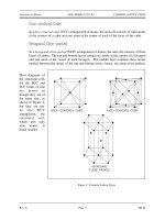
Thermal stresses are a major concern in
Figure 1 Stress on Reactor Vessel Wall
reactor systems due to the magnitude of the
stresses involved. With rapid heating (or
cooling) of a thick-walled vessel such as
the reactor pressure vessel, one part of the
wall may try to expand (or contract) while
the adjacent section, which has not yet been
exposed to the temperature change, tries to
restrain it. Thus, both sections are under
stress. Figure 1 illustrates what takes place.
A vessel is considered to be thick-walled or
thin-walled based on comparing the
thickness of the vessel wall to the radius of
the vessel. If the thickness of the vessel
wall is less than about 1 percent of the
vessel's radius, it is usually considered a
thin-walled vessel. If the thickness of the
vessel wall is more than 5 percent to 10
percent of the vessel's radius, it is
considered a thick-walled vessel. Whether
a vessel with wall thickness between 1
percent and 5 percent of radius is
considered thin-walled or thick-walled
depends on the exact design, construction,
and application of the vessel.
When cold water enters the vessel, the cold water causes the metal on the inside wall (left side
of Figure 1) to cool before the metal on the outside. When the metal on the inside wall cools,
it contracts, while the hot metal on the outside wall is still expanded. This sets up a thermal
stress, placing the cold side in tensile stress and the hot side in compressive stress, which can
cause cracks in the cold side of the wall. These stresses are illustrated in Figure 2 and Figure 3
in the next chapter.
The heatup and cooldown of the reactor vessel and the addition of makeup water to the reactor
coolant system can cause significant temperature changes and thereby induce sizable thermal
stresses. Slow controlled heating and cooling of the reactor system and controlled makeup
water addition rates are necessary to minimize cyclic thermal stress, thus decreasing the
potential for fatigue failure of reactor system components.
Operating procedures are designed to reduce both the magnitude and the frequency of these
stresses. Operational limitations include heatup and cooldown rate limits for components,
temperature limits for placing systems in operation, and specific temperatures for specific
pressures for system operations. These limitations permit material structures to change
temperature at a more even rate, minimizing thermal stresses.
MS-03 Page 4 Rev. 0
Thermal Shock DOE-HDBK-1017/2-93 THERMAL STRESS
Summary
The important information in this chapter is summarized below.
Thermal Stress Summary
Two types of stress that can be caused by thermal shock are:
Tensile stress
Compressive stress
Causes of thermal shock include:
Nonuniform heating (or cooling) of a uniform material
Uniform heating (or cooling) of a nonuniform material
Thermal shock (stress) on a material, can be calculated using Hooke's Law from
the following equation. It can lead to the failure of a vessel.
F/A = Eα∆T
Thermal stress is a major concern due to the magnitude of the stresses involved
with rapid heating (or cooling).
Operational limits to reduce the severity of thermal shock include:
Heatup and cooldown rate limits
Temperature limits for placing systems into operation
Specific temperatures for specific pressures for system operation
Rev. 0 Page 5 MS-03
PRESSURIZED THERMAL SHOCK DOE-HDBK-1017/2-93 Thermal Shock
PRESSURIZED THERMAL SHOCK
Personnel need to be aware how pressure combined with thermal stress can cause
failure of plant materials. This chapter addresses thermal shock (stress) with
pressure excursions.
EO 1.6 DEFINE the term pressurized thermal shock.
EO 1.7 STATE how the pressure in a closed system effects the severity
of thermal shock.
EO 1.8 LIST the four plant transients that have the greatest potential
for causing thermal shock.
EO 1.9 STATE the three locations in a reactor system that are of
primary concern for thermal shock.
Definition
One safety issue that is a long-term problem brought on by the aging of nuclear facilities is
pressurized thermal shock (PTS). PTS is the shock experienced by a thick-walled vessel due to
the combined stresses from a rapid temperature and/or pressure change. Nonuniform temperature
distribution and subsequent differential expansion and contraction are the causes of the stresses
involved. As the facilities get older in terms of full power operating years, the neutron radiation
causes a change in the ductility of the vessel material, making it more susceptible to
embrittlement. Thus, if an older reactor vessel is cooled rapidly at high pressure, the potential
for failure by cracking increases greatly.
Evaluating Effects of PTS
Changes from one steady-state temperature or pressure to another are of interest for evaluating
the effects of PTS on the reactor vessel integrity. This is especially true with the changes
involved in a rapid cooldown of the reactor system, which causes thermal shock to the reactor
vessel. These changes are called transients. Pressure in the reactor system raises the severity
of the thermal shock due to the addition of stress from pressure. Transients, which combine high
system pressure and a severe thermal shock, are potentially more dangerous due to the added
effect of the tensile stresses on the inside of the reactor vessel wall. In addition, the material
toughness of the reactor vessel is reduced as the temperature rapidly decreases.
MS-03 Page 6 Rev. 0