Material Science_ Vol 2 of 2 - US DOE (1993) WW part 6 ppsx
Bạn đang xem bản rút gọn của tài liệu. Xem và tải ngay bản đầy đủ của tài liệu tại đây (205.59 KB, 8 trang )
DOE-HDBK-1017/2-93
Brittle Fracture MINIMUM PRESSURIZATION-TEMPERATURE CURVES
MINIMUM PRESSURIZATION-TEMPERATURE CURVES
Plant operations are effected by the minimum pressurization-temperature curves.
Personnel need to understand the information that is associated with the curves
to better operate the plant.
EO 1.8 STATE the two bases used for developing a minimum
pressurization-temperature curve.
EO 1.9 EXPLAIN a typical minimum pressure-temperature curve
including:
a. Location of safe operating region
b. The way the curve will shift due to irradiation
EO 1.10 LIST the normal actions taken, in sequence, if the minimum
pressurization-temperature curve is exceeded during critical
operations.
EO 1.11 STATE the precaution for hydrostatic testing.
MPT Definition and Basis
Minimum pressurization-temperature (MPT) curves specify the temperature and pressure
limitations for reactor plant operation. They are based on reactor vessel and head stress
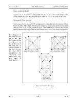
limitations and the need to preclude reactor vessel and head brittle fracture. Figure 4 shows some
pressure-temperature operating curves for a pressurized water reactor (PWR) Primary Coolant
System (PCS).
Note that the safe operating region is to the right of the reactor vessel MPT curve. The reactor
vessel MPT curve ensures adequate operating margin away from the crack arrest curve discussed
above. The curves used by operations also incorporate instrument error to ensure adequate safety
margin. Because of the embrittling effects of neutron irradiation, the MPT curve will shift to the
right over core life to account for the increased brittleness or decreased ductility. Figure 4 also
contains pressurizer and steam generator operating curves. Operating curves may also include
surge line and primary coolant pump operating limitations. The MPT relief valve setting prevents
exceeding the NDT limit for pressure when the PCS is cold and is set below the lowest limit of
the reactor vessel MPT curve.
Rev. 0 Page 7 MS-04
DOE-HDBK-1017/2-93
MINIMUM PRESSURIZATION-TEMPERATURE CURVES Brittle Fracture
Figure 4 PCS Temperature vs. Pressure for Normal Operation
MS-04 Page 8 Rev. 0
DOE-HDBK-1017/2-93
Brittle Fracture MINIMUM PRESSURIZATION-TEMPERATURE CURVES
If the limit of the MPT curve is exceeded during critical operation, the usual action is to scram
the reactor, cool down and depressurize the PCS, and conduct an engineering evaluation prior
to further plant operation.
During hydrostatic testing, minimum pressurization temperature precautions include making sure
that desired hydrostatic pressure is consistent with plant temperatures so that excessive stress does
not occur. Figure 5 shows MPT curves for hydrostatic testing of a PWR PCS. The safe
operating region is to the right of the MPT curves. Other special hydrostatic limits may also
apply during testing.
Figure 5 PCS Temperature vs. Hydrotest Pressure
Rev. 0 Page 9 MS-04
DOE-HDBK-1017/2-93
MINIMUM PRESSURIZATION-TEMPERATURE CURVES Brittle Fracture
Summary
The important information in this chapter is summarized below.
Minimum Pressurization-Temperature Curves Summary
MPT curves are based on reactor vessel and head stress limitations, and the need
to prevent reactor vessel and head brittle fracture.
MPT curve safe operating region is to the right of the curve.
MPT curve will shift to the right due to irradiation.
Normal actions if MPT curves are exceeded during critical operation are:
Scram reactor
Cool down and depressurize
Conduct engineering evaluation prior to further plant operation
The precaution to be observed when performing a hydrostatic test is to make sure
the pressure is consistent with plant temperatures.
MS-04 Page 10 Rev. 0
DOE-HDBK-1017/2-93
Brittle Fracture HEATUP AND COOLDOWN RATE LIMITS
HEATUP AND COOLDOWN RATE LIMITS
Personnel operating a reactor plant must be aware of the heatup and cooldown
rates for the system. If personnel exceed these rates, major damage could occur
under certain conditions.
EO 1.12 IDENTIFY the basis used for determining heatup and cooldown
rate limits.
EO 1.13 IDENTIFY the three components that will set limits on the heatup
and cooldown rates.
EO 1.14 STATE the action typically taken upon discovering the heatup or
cooldown rate has been exceeded.
EO 1.15 STATE the reason for using soak times.
EO 1.16 STATE when soak times become very significant.
BasisBasis
Figure 6 Heatup and Cooldown Rate Limits
Heatup and cooldown rate limits, as
shown in Figure 6, are based upon the
impact on the future fatigue life of the
plant. The heatup and cooldown
limits ensure that the plant's fatigue
life is equal to or greater than the
plant's operational life. Large
components such as flanges, the
reactor vessel head, and even the
reactor vessel itself are the limiting
components. Usually the most
limiting component will set the heatup
and cooldown rates.
Thermal stress imposed by a rapid
temperature change (a fast ramp or
even a step change) of approximately
20
°F (depending upon the plant) is
insignificant (10
6
cycles allowed
depending upon component) and has no effect on the design life of the plant.
Rev. 0 Page 11 MS-04
DOE-HDBK-1017/2-93
HEATUP AND COOLDOWN RATE LIMITS Brittle Fracture
ExceedingExceeding HeatupHeatup andand CooldownCooldown RatesRates
Usually, exceeding heatup or cooldown limits or other potential operational thermal transient
limitations is not an immediate hazard to continued operation and only requires an assessment
of the impact on the future fatigue life of the plant. However, this may depend upon the
individual plant and its limiting components.
Individual components, such as the pressurizer, may have specific heatup and cooldown
limitations that, in most cases, are less restrictive than for the PCS.
Because of the cooldown transient limitations of the PCS, the reactor should be shut down in an
orderly manner. Cooldown of the PCS from full operating temperature to 200
°F or less requires
approximately 24 hours (depending upon cooldown limit rates) as a minimum. Requirements
may vary from plant to plant.
SoakSoak TimesTimes
Soak times may be required when heating up the PCS, especially when large limiting components
are involved in the heatup. Soak times are used so that heating can be carefully controlled. In
this manner thermal stresses are minimized. An example of a soak time is to heat the reactor
coolant to a specified temperature and to stay at that temperature for a specific time period. This
allows the metal in a large component, such as the reactor pressure vessel head, to heat more
evenly from the hot side to the cold side, thus limiting the thermal stress across the head. Soak
time becomes very significant when the PCS is at room temperature or below and very close to
its RT
NDT
temperature limitations.
MS-04 Page 12 Rev. 0
DOE-HDBK-1017/2-93
Brittle Fracture HEATUP AND COOLDOWN RATE LIMITS
SummarySummary
The important information in this chapter is summarized below.
Heatup-Cooldown Rate Li mits Summary
Heatup and cooldown rate limits are based upon impact on the future fatigue life
of the plant. The heatup and cooldown rate limits ensure that the plant's fatigue
life is equal to or greater than the plant's operational life.
Large components such as flanges, reactor vessel head, and the vessel itself are the
limiting components.
Usually exceeding the heatup or cooldown rate limits requires only an assessment
of the impact on the future fatigue life of the plant.
Soak times:
May be required when heating large components
Used to minimize thermal stresses by controlling the heating rate
Become very significant if system is at room temperature or below and
very close to RT
NDT
temperature limitations
Rev. 0 Page 13 MS-04
DOE-HDBK-1017/2-93 Brittle Fracture
Intentionally Left Blank.
MS-04 Page 14 Rev. 0