Soil and Environmental Analysis: Physical Methods - Chapter 5 pot
Bạn đang xem bản rút gọn của tài liệu. Xem và tải ngay bản đầy đủ của tài liệu tại đây (810.09 KB, 55 trang )
5
Unsaturated Hydraulic Conductivity
Christiaan Dirksen
Wageningen University, Wageningen, The Netherlands
I. INTRODUCTION
The unsaturated zone plays an important role in the hydrological cycle. It forms
the link between surface water and ground water and has a dominant influence on
the partitioning of water between them. The hydraulic properties of the unsatu-
rated zone determine how much of the water that arrives at the soil surface will
infiltrate into the soil, and how much will run off and may cause floods and ero-
sion. In many areas of the world, most of the water that infiltrates into the ground
is transpired by plants or evaporated directly into the atmosphere, leaving only
a small proportion to percolate deeper and join the ground water. Surface runoff
and deep percolation may carry pollutants with them. Then it is important to know
how long it will take for this water to reach surface or ground water resources.
Besides providing water for plants to transpire, the unsaturated zone also
provides oxygen and nutrients to plant roots, thus having a dominant influence on
food and fiber production. Water content also determines soil strength, which af-
fects anchoring of plants, root penetration, compaction by cattle and machinery,
and tillage operations. To mention just one other role of the unsaturated zone, its
water content has a great influence on the heat balance at the soil surface. This is
well illustrated by the large diurnal temperature variations in deserts.
To understand and describe these and other processes, the hydraulic prop-
erties that govern water transport in the soil must be quantified. Of these, the
unsaturated hydraulic conductivity is, if not the most important, certainly the
most difficult to measure accurately. It varies over many orders of magnitude not
only between different soils but also for the same soil as a function of water con-
tent. Much has been published on the determination and/or measurement of the
Copyright © 2000 Marcel Dekker, Inc.
unsaturated hydraulic conductivity, including reviews (Klute and Dirksen, 1986;
Green et al., 1986; Mualem, 1986a; Kool et al., 1987; Dirksen, 1991; Van Genuch-
ten et al., 1992, 1999). There is no single method that is suitable for all soils and
circumstances. Methods that require taking ‘‘undisturbed’’ samples are not well
suited for soils with many stones or with a highly developed, loose structure. It is
better to select an in situ method for such soils. Hydraulic conductivity for rela-
tively dry conditions cannot be measured in situ when the soil in its natural situ-
ation is always wet. It is then necessary to take samples and dry them first. The
latter process presents problems if the soil shrinks excessively on drying. These
and other factors that influence the choice between laboratory and field methods
are discussed separately in Sec. IV.
Selection of the most suitable method for a given set of conditions is a major
task. The literature is so extensive that it is neither necessary nor possible to give
a complete review and evaluation of all available methods. Instead, I have focused
on what I think should be the selection criteria (Sec. III) and described the most
familiar types of methods (in Secs. VI to IX) with these criteria in mind. This
includes some very recent work. The need for and selection of a standard method
is discussed separately in Sec. V. Since some of the methods used to study infiltra-
tion are also used to determine unsaturated hydraulic conductivity, reference is
made to the appropriate section in Chap. 6 where relevant.
There are two soil water transport functions which, under restricting condi-
tions, can be used instead of hydraulic conductivity, namely hydraulic diffusivity
and matric flux potential. Diffusivity can be measured directly in a number of
ways that are easier and faster than the methods available for hydraulic conductiv-
ity. Moreover, the latter can also be derived from the former. The same is true for
yet another transport function, the sorptivity, which can also be measured more
easily than the hydraulic conductivity. At the outset I have summarized the theory
and transport coefficients used to describe water transport in the unsaturated zone
(Sec. II). Theoretical concepts and equations associated with specific methods
are given with the discussion of the individual methods. Readers who have little
knowledge of the physical principles involved in unsaturated flow and its mea-
surement can find these discussed at a more detailed and elementary level in soil
physics textbooks (Hillel, 1980; Koorevaar et al., 1983; Hanks, 1992; Kutilek and
Nielsen, 1994) and would be advised to consult one of these before attempting
this chapter.
Apparatus for determining unsaturated hydraulic conductivity is not usually
commercially available as such. However, many of the methods involve the mea-
surement of water content, hydraulic head and/or the soil water characteristic, and
methods and commercial supplies of equipment to determine these properties are
given in Chaps. 1, 2, and 3, respectively. Where specialized or specially con-
structed equipment is required, this is indicated with the discussion of individual
methods.
184 Dirksen
Copyright © 2000 Marcel Dekker, Inc.
In general, it is difficult if not impossible to measure the soil hydraulic trans-
port functions quickly and/or accurately. Therefore it is not surprising that at-
tempts have been made to derive them indirectly. The derivation of the hydraulic
transport properties from other, more easily measured soil properties is discussed
in Sec. X, and the inverse approach of parameter optimization in Sec. XI.
II. TRANSPORT COEFFICIENTS
A. Hydraulic Conductivity
In general, water transport in soil occurs as a result of gradients in the hydraulic
potential (Koorevaar et al., 1983):
H ϭ h ϩ z (1)
where H is the hydraulic head, h is the pressure head, and z is the gravitational
head or height above a reference level. These symbols are generally reserved for
potentials on a weight basis, having the dimension J/N ϭ m. Although h is called
a pressure head, in unsaturated flow it will have a negative value with respect to
atmospheric pressure and can be referred to as a suction or tension. In rigid soils
there exists a relationship between volumetric water content or volume fraction of
water, u(m
3
m
Ϫ3
), and pressure head, called the soil water retention characteris-
tic, u[h] (see Chap. 3). Here, and throughout this chapter, square brackets are used
to indicate that a variable is a function of the quantity within the brackets. The
function u[h] often depends on the history of wetting and drying; this phenome-
non is called hysteresis. Water transport in soils obeys Darcy’s law, which for one-
dimensional vertical flow in the z-direction, positive upward, can be written as
ץH ץh
q ϭϪk[u] ϭϪk[u] Ϫ k[u](2)
ץz ץz
where q is the water flux density (m
3
m
Ϫ2
s ϭ ms
Ϫ1
) and k[u] is the hydraulic con-
ductivity function (m s
Ϫ1
). k is a function of u, since water content determines the
fraction of the sample cross-sectional area available for water transport. Indirectly,
k is also a function of the pressure head. k[h] is hysteretic to the extent that u[h]is
hysteretic. Hysteresis in k[u] is second order and is generally negligible. Determi-
nations of k usually consist of measuring corresponding values of flux density and
hydraulic potential gradient, and calculating k with Eq. 2. This is straightforward
and can be considered as a standard for other, indirect measurements.
B. Hydraulic Diffusivity
For homogeneous soils in which hysteresis can be neglected or in which only
monotonically wetting or drying flow processes are considered, h[u]isasingle-
Unsaturated Hydraulic Conductivity 185
Copyright © 2000 Marcel Dekker, Inc.
valued function. Then, for horizontal flow in the x-direction, or when gravity can
be neglected, Eq. 2 yields
ץu dh
q ϭ D [u] for D[u] ϭ k[u] (3)
ͩͪ
ץxdu
where D[u] is the hydraulic diffusivity function (m s
Ϫ2
). Thus under the above
stated conditions, the water content gradient can be thought of as the driving force
for water transport, analogous to a diffusion process. Of course, the real driving
force remains the pressure head gradient. Therefore, D[u] is different for wetting
and drying. There are many methods to determine D[u], some of which are de-
scribed later. They usually require a special theoretical framework with simplify-
ing assumptions. Once D[u] and h[u] are known, the hydraulic conductivity func-
tion can be calculated according to
du
k[u] ϭ D[u][u] (4)
ͩͪ
dh
Because of hysteresis, one should combine only diffusivities and derivatives of
soil water retention characteristics that are both obtained either by wetting or by
drying. Since k[u] is basically nonhysteretic, the k[u] functions obtained in the
two ways should agree closely.
C. Matric Flux Potential
Water transport in soils in response to pressure potential gradients can also be
described in terms of the matric flux potential (Raats and Gardner, 1971):
h u
f ϭ ͵ k[h] dh ϭ ͵ D[u]du (5)
Ϫϱ 0
Equation 3 then becomes
ץf
q ϭ (6)
ץz
The matric flux potential (m
2
s
Ϫ1
) integrates the transport coefficient and the driv-
ing force. In homogeneous soil without hysteresis, the horizontal water flux den-
sity is simply equal to the gradient of f. This formulation of the water transport
process offers distinct advantages in certain situations, especially in the simulation
of water transport under steep potential gradients (Ten Berge et al., 1987). It also
allows one to obtain analytical solutions for steady-state multidimensional flow
problems, including gravity, where the hydraulic conductivity is expressed as an
exponential function of pressure head (Warrick, 1974; Raats, 1977). Like k and
D, f is a soil property that characterizes unsaturated water transport and is a direct
186 Dirksen
Copyright © 2000 Marcel Dekker, Inc.
function of u and only indirectly of h. A method for measuring f directly is de-
scribed in Sec. VI.E.
D. Sorptivity
Sorptivity is an integral soil water property that contains information on the soil
hydraulic properties k[u] and D[u], which can be derived from it mathematically
(Philip, 1969). Generally, sorptivities can be measured more accurately and/or
more easily than k[u] and D[u], so it is worth considering whether to determine
the latter in this indirect way (Dirksen, 1979; White and Perroux, 1987). One-
dimensional absorption (gravity negligible), initiated at time t ϭ 0 by a step-
function increase of water content from u
0
to u
1
at the soil surface, x ϭ 0, is
described by
1/2
I ϭ S[u , u ] t (7)
10
where I is the cumulative amount of absorbed water (m) at any given time t, and
sorptivity S (m s
Ϫ1/2
) is a soil property that depends on the initial and final water
content, usually saturation. Saturated sorptivity characterizes ponding infiltration
at small times, as it is the first term in the infiltration equation of Philip (1969)
and equal to the amount of water absorbed during the first time unit. With the flux-
controlled sorptivity method (Sec. VIII.F), the dependence of S on u
1
at constant
u
0
is determined experimentally. From this, D[u] can be derived algebraically (see
Eq. 20, below). The t
1/2
-relationship of Eq. 7 has also been used for scaling soils
and estimating hydraulic conductivity and diffusivity of similar soils (Sec. X.D).
III. SELECTION FRAMEWORK
A. Types of Methods
There are many published methods for determining soil water transport proper-
ties. No single method is best suited for all circumstances. Therefore it is neces-
sary to select the method most suited to any given situation. Time spent on this
selection is time well spent. Table 1 lists various types of methods that have been
proposed and evaluates them on a scale of 1 to 5 using the selection criteria listed
in Table 2. These tables form the nucleus of this chapter. In subsequent sections,
the various methods are reviewed in varying detail. In general, the theoretical
framework and/or main working equations are described, and other pertinent in-
formation is added to help substantiate the scores given in Table 1. For the more
familiar methods, mostly only evaluating remarks are made; some experimental
details are given also for the less familiar and newest methods. The scores are a
reflection of my own insight and experience and are not based solely on the infor-
mation provided. Further information is given in the references quoted.
Unsaturated Hydraulic Conductivity 187
Copyright © 2000 Marcel Dekker, Inc.
Table 1 Evaluation of Methods to Measure Soil Water Transport Properties According to Criteria and Gradations in Table 2
Method
Criteria
ABCDEFGHI JKL
steady state
Laboratory
Head-controlled 5 5 5 3(5) 5 3 2(1) 3(2) 3(2) 4 4 4
Flux-controlled 5 5 5 3(5) 5 3(4) 3(2) 3(1) 3(2) 4(3) (4)2 4
Steady-rate (long column) 5 4 4 4 5 2 1 3 3 5 4 4
Regulated evaporation 5 2 2 3 3 2 2 3 3 4 2 4
Matric flux potential 3 3 3 5 3 3 3 4 4 5 5 4
Field
Sprinkling infiltrometer 5 4 3 2 5 3(4) 2(1) 1 2 1 1 3
Isolated column (crust) 5 4 3 3 2 2 3 3 3 2 2 3
Spherical cavity 5 4 3 3 3 4 2 4 2 3 4 3
Tension disk infiltrometer 5, 3 2 3 5 3 2 4 2 4 3 2 3
transient
Laboratory
Pressure plate outflow 4 24532234343
One-step outflow 4 24532334343
Boltzmann, fixed time 4 4 5 2 1 5 4 3 4 5 3 3
Boltzmann, fixed position 4 4 5 2 1 5 5 1 2 4 2 2
Hot air 4 4 1 4 1 5 4 4 4 4 3 2
Flux-controlled sorptivity 4 4, 2 5 4 3 5 4 3(1) 3 3 2 4
Instantaneous profile 5 55223222222
Wind evaporation 5 3 5 3 4 4 2 2 3 3 4 4
Field
Instantaneous profile 5 53223222222
Unit gradient, prescribed 5 2 3 2 2 3 3 4 2 2 4 2
Unit gradient, simple 5, 4 1 1 4 2 3 2 4 3 3 4 2
Sprinkling infiltrometer 5 4 3 2 2 3 2 1 1 1 1 2
Copyright © 2000 Marcel Dekker, Inc.
A major division is made between steady-state and transient measurements.
In the first category, all parameters are constant in time. For this reason, steady-
state measurements are almost always more accurate than transient measurements,
usually even with less sophisticated equipment. Their main disadvantage is that
they take much more time, often prohibitively so. Therefore, the choice between
Unsaturated Hydraulic Conductivity 189
Table 2 Selection Criteria and Gradations for Methods to Measure Soil Water Transport Properties
A. Determined parameter
5. Hydraulic conductivity
4. Hydraulic diffusivity
3. Matric flux potential
2. Sorptivity
1. Any other transport property
B. Theoretical basis
5. Simple Darcy law or rigorously exact
4. Exact, or minor simplifying assumptions
3. Quasi-exact, simplifying assumptions
2. Major simplifying assumptions
1. Minimal theoretical basis
C. Control of initial or boundary conditions
5. Exact, no requirements
4. Indirect and accurate
3. Approximate
2. Approximate part of the time
1. Little control, if any
D. Accuracy of measurements
5. Weight, water volume, time
4. Water content measurements, direct
3. Pressure head measurements
2. Indirect calibrated measurements
1. Approximate uncalibrated measurements
E. Error propagation in data analysis
5. Simple quotient (Darcy law)
4. Accurate operations on accurate data
3. Inaccurate operations on accurate data
2. Accurate operations on inaccurate data
1. Inaccurate operations on inaccurate data
F. Range of application
5. Saturation to wilting point (h ϾϪ160 m)
4. Tensiometer range (h ϾϪ8.5 m)
3. Hydrological range (k Ͼ 0.1 mm/d)
2. Wet range (h ϾϪ0.5 m)
1. Psychrometer range (Ϫ10 Ͼ h ϾϪ160 m)
G. Duration of method
5. 1 hour
4. 1 day
3. 1 week
2. 1 month
1. More than 1 month
H. Equipment
5. Standard for soil laboratory
4. General-purpose, off-the-shelf
3. Easily made in average machine shop
2. Special-purpose, off-the-shelf
1. Special-purpose, custom-made
I. Operator skill
5. No special skill required
4. Some practice required
3. General measuring experience adequate
2. Special training of experimentalist
1. Highest degree of specialization needed
J. Operator time
5. Few simple and fast operations
4. Few elaborate operations
3. Repeated simple and fast operations
2. Repeated elaborate operations
1. Operator required continuously
K. Simultaneous measurements
5. No limit
4. Large number, at significant cost
3. Small number, at little cost
2. Small number, at substantial cost
1. No potential
L. Check on measurements
5. Continuous monitoring of all parameters
4. Easy verification at all times
3. Each verification requires effort
2. Single check is major effort
1. Check not possible
Copyright © 2000 Marcel Dekker, Inc.
these two categories usually involves balancing costs, time available, and the re-
quired accuracy. For one-dimensional infiltration in a long soil column and for
three-dimensional infiltration in general, the infiltration rate after some time be-
comes steady, but the flow system as a whole is transient due to the progressing
wetting front. These flow processes, therefore, form an intermediate category that
will be characterized as steady-rate.
The methods are divided further into field and laboratory methods, the
choice of which is discussed in Sec. IV. Methods for measuring soil water trans-
port coefficients can also be divided into those that measure hydraulic conductivity
directly and all other methods (column A). From what follows it should become
clear that one should measure hydraulic conductivity as a function of volumetric
water content, whenever possible. When the hydraulic diffusivity is measured or
the hydraulic conductivity as a function of pressure head, it is important to make
a distinction between wetting and drying flow regimes in view of the hysteretic
character of soil water retention.
B. Selection Criteria
The methods listed in Table 1 are evaluated on the basis of the criteria in Table 2,
which include the following: the degree of exactness of the theoretical basis (B),
the experimental control of the required initial and boundary conditions (C),
the inherent accuracy of the measurements (D), the propagation of errors in the
experimental data during the calculation of the final results (E), the range of ap-
plication (F), the time (duration) required to obtain the particular transport coef-
ficient function over the indicated range of application (G), the necessary invest-
ment in workshop time and/or money (H), the skill required by the operator (I),
the operator time required while the measurements are in progress (J), the poten-
tial for measurements to be made simultaneously on many soil samples (K), and
the possibility for checking during and/or after the measurements (L).
Depending on the particular situation, only a few or all of these criteria must
be taken into account to make a proper choice. For example, accuracy will be a
prime consideration for detailed studies of water transport processes at a particular
site, whereas for a study of spatial variability the ability to make a large number
of measurements in a reasonably short time is mandatory. These often do not have
to be very accurate. If the absolute accuracy of a newly developed method must
be established, the most accurate method already available should be selected,
since there is no ‘‘standard’’ material with known properties available with which
the method can be tested. The need and selection of a ‘‘standard method’’ for this
purpose is discussed in Sec. V. When facilities for routine measurements must be
set up, the last four criteria are particularly pertinent. Finally, there may be par-
ticular (difficult) conditions under which one method is more suitable than others,
190 Dirksen
Copyright © 2000 Marcel Dekker, Inc.
and these conditions may dominate the choice of method. Such criteria are not
covered by Table 1 but are mentioned with the description of individual methods
when appropriate.
The selection criteria used (Table 2) are mostly self-explanatory and will
become clearer with the discussion of the individual methods. At this stage only
a few general remarks are made about accuracy (relating to criteria B–E) and the
range of application (G), which, out of practical considerations, is associated with
pressure heads. For examples, reference is made to methods that are described
later in more detail.
C. Accuracy
Direct measurements of weight, volume of water, and time, made in connection
with the determination of soil hydraulic properties, are simple and very accurate
(maximum score 5). An exception is measuring very small volumes of water while
maintaining a particular experimental setup, for example a small hydraulic head
gradient. Although the mass and water content of a soil sample can usually be
measured accurately, the water content may not conform to what it should be
according to the theoretically assumed flow system. For example, for Boltzmann
transform methods a water content profile must be determined after an exact time
period of wetting or drying. Gravimetric determinations cannot be performed in-
stantaneously; during the destructive sampling water contents will change due to
redistribution and evaporation of water and due to manipulation of the soil. Indi-
rect water content measurements can be made nondestructively and repeatedly
during a flow process. For high accuracy, these measurements normally require
extensive calibration under identical conditions; usually this is not possible or
takes too much time.
Derivation of hydraulic properties from other measured parameters intro-
duces two kinds of errors. Firstly, the theoretical basis of the method may not be
exact, either because it involves simplifying assumptions or because the theoreti-
cal analysis of the water flow process yields only an approximation of the trans-
port property. Secondly, errors in the primary experimental data are propagated in
the calculations required to obtain the final results. Mathematical manipulations
each have their own inherent inaccuracies, a good example being differentiation.
Another common source of error is that the theoretically required initial and/or
boundary conditions cannot be attained experimentally. For example, it is impos-
sible to impose the step-function decrease of the hydraulic potential at the soil
surface under isothermal conditions, as is assumed with the hot air method.
Hydraulic potential measurements are relatively difficult and can be very
inaccurate. Water pressure inside tensiometers in equilibrium with the soil water
around the porous cup can in principle be measured to any desired accuracy with
Unsaturated Hydraulic Conductivity 191
Copyright © 2000 Marcel Dekker, Inc.
pressure transducers, but temperature variations can render such measurements
very inaccurate. Mercury manometers are probably the least sensitive to large
errors, but their accuracy is at best about Ϯ 2 cm (Chap. 2). Near saturation,
water manometers should respond quickly to changing pressure heads with an
accuracy of about Ϯ 1 mm. Beyond the tensiometer range, soil matric potentials
are mostly determined indirectly from soil water characteristics or by measuring
the electrical conductivity, heat diffusivity, or other properties of probes in equilib-
rium with soil water, with all the inaccuracies associated with indirect measure-
ments. Direct measurements can be made with psychrometers (which also mea-
sure the osmotic component of the soil water potential) but these can be used only
by workers experienced with sophisticated equipment and are at best accurate to
about Ϯ 500 cm. However, for many studies, such as that of the soil-water-plant-
atmosphere continuum, such accuracies are acceptable, because hydraulic con-
ductivities in this dry range are so low that hydraulic head gradients must be very
large to obtain significant flux densities.
D. Range of Application
The range of application of a particular method depends to a large extent on
whether, and if so how, soil water potentials are to be measured. For convenience
and based on practical experience, therefore, the range of application is character-
ized in somewhat vague terms, which are identified further by approximate ranges
of pressure head or flux density. Tensiometers can theoretically be used down to
pressure heads of about Ϫ8.5 m, but in practice air intrusion usually causes prob-
lems at much higher values. Fortunately, hydraulic transport properties need not
be known in the drier range, except where water transport over small distances is
concerned (e.g., evaporation at the soil surface, and water transport to individual
plant roots). Water transport over large distances occurs mostly in the saturated
zone (or as surface water), for which the saturated hydraulic conductivity must be
known. However, there are some exceptions, such as saline seeps, which are
caused by unsaturated water transport over large distances during many years.
Although unsaturated water transport normally occurs over short distances, it
plays a key role in hydrology, as mentioned in the introduction. The unsteady,
mostly vertical water transport in soil profiles is only significant when the hydrau-
lic conductivity is in the range from the maximum value at saturation to values
down to about 0.1 mm d
Ϫ1
, since precipitation, transpiration, and evaporation can
generally not be measured to that accuracy. This ‘‘hydrological’’ range (k Ͼ
0.1 mm d
Ϫ1
) corresponds to a pressure head range between 0 and Ϫ1.0 to Ϫ2.0 m,
depending on the soil type.
The pressure head range over which hydraulic transport properties must be
known should be carefully considered and be a major consideration in the selec-
192 Dirksen
Copyright © 2000 Marcel Dekker, Inc.
tion process. It makes no sense, for instance, to determine hydraulic conductivities
with the hot air method (which yields very inaccurate results over the entire pres-
sure head range) when the results are only required for use in the hydrological
range, for which much better methods are available. Conversely, it is dangerous
to select an attractive method suitable only in the wetter range and to extrapolate
the results to a drier range. In practice, the range of application of a particular
method depends also on the time required to attain appropriate measurement con-
ditions. Criteria F and G are interdependent: the time needed to measure the soil
water property function often increases exponentially as the range of potentials is
extended to lower values.
E. Alternative Approaches
Because measurements of the soil water transport properties leave much to be
desired in terms of their accuracy, cost, applicability, and time, it is not surprising
that other ways to obtain these soil properties have been investigated. The most
extreme of these approaches is not to make any water transport measurements,
but to derive the water transport functions from other, more easily measured soil
properties (e.g., particle size distribution and soil water retention characteristic).
These procedures are usually based on a theoretical model of the relationship, but
they can also be of a purely statistical nature, in which case one should be cautious
in applying the results to soil types outside the range used to derive the relation-
ship. An intermediate approach forms the so-called inverse or ‘‘parameter optim-
ization’’ techniques, which have recently received renewed attention. To be able
to decide how the hydraulic transport functions can best be determined in a given
situation, the possibilities and limitations of these alternative approaches should
also be considered. They are briefly described in Secs. X and XI.
IV. LABORATORY VERSUS FIELD METHODS
A. Working Conditions
A major division between available methods is that of laboratory versus field
methods. Laboratory measurements have many advantages over field measure-
ments. In the laboratory, facilities such as electricity, gas, water, and vacuum are
available, and temperature variations are usually modest and controllable. Stan-
dard equipment (e.g., balances and ovens) is also more readily available than in
the field. Expensive and delicate equipment can often not be used in the field
because of weather conditions, theft, vandalism, etc. One can usually save much
time by working in the laboratory. Samples from many different locations can then
first be collected and measurements carried out consecutively or in series. Consid-
Unsaturated Hydraulic Conductivity 193
Copyright © 2000 Marcel Dekker, Inc.
ering all these advantages, it would seem good practice to carry out measurements
in the laboratory, unless there are overriding reasons to perform them in situ. This
may be necessary for experiments involving plants, but in situ hydraulic conduc-
tivity measurements are normally only needed to determine the hydraulic proper-
ties of a strongly layered soil profile as a whole or when heterogeneity and in-
stability of soil structure make it very difficult if not impossible to obtain large
enough, undisturbed soil samples and transport them to the laboratory.
B. Sampling Techniques
Because the hydraulic conductivity of soil is very sensitive to changes in soil
structure due to sampling and/or preparation procedures, these operations should
be carried out with utmost care. Fractures formed during sampling that are ori-
ented in the direction of flow are disastrous for saturated hydraulic conductivity
determinations but have very little influence on unsaturated hydraulic conductivi-
ties. Fractures perpendicular to the direction of flow have the very opposite effect
on both types of measurements.
To obtain as nearly ‘‘undisturbed’’ soil samples as possible, soil columns
have been isolated in situ by carefully excavating the surrounding soil and shaving
off the top soil to the desired depth. Usually, a plaster of Paris jacket is cast around
the soil column to facilitate applying water from an airtight space above the soil
surface (needed, e.g., for the crust method), installing tensiometers, etc. The
jacket also allows saturated measurements (it is not necessary to seal the soil col-
umn for unsaturated measurements) and protects the soil column in the field and
during transport to a laboratory. Somewhat more disturbed soil columns from en-
tire soil profiles can be obtained by driving a cylinder, supplied with a sharp,
hardened steel cutting edge, into the soil with a hydraulic press. If the stroke of
this press is smaller than the height of the sample, care should be taken to maintain
exactly the same alignment for each stroke. We have been able to accomplish this
easily and satisfactorily by pushing a sample holder hydraulically against a hori-
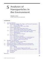
zontal crossbar anchored firmly by four widely spaced tie lines (Fig. 1). To reduce
compaction of the soil inside the cylinder due to the friction between the cylinder
wall and the soil, the diameter of the cylinder should be kept large and/or a sam-
pling tool with a moving sleeve should be used (Begemann, 1988). Driving cyl-
inders into the ground by repeated striking with a hammer should not be tolerated
for quantitative work, not even for short samples, because of the lateral forces that
are likely to be applied. A compromise between a hammer and a hydraulic press
is a cylindrical weight that, sliding along a steady vertical rod, is dropped repeat-
edly onto a sampleholder. For measurements of hydraulic conductivity of packed
soil columns, it is essential that the packing be done systematically to attain the
best possible reproducibility and uniformity. At the moment this appears to be
more an art than a science.
194 Dirksen
Copyright © 2000 Marcel Dekker, Inc.
C. Sample Representativeness
Other important aspects of soil sampling are the size and number of samples re-
quired to be representative in view of soil heterogeneity and spatial variability.
The development and size of the natural structural units (peds) dictate the size of
the sample needed for a particular measurement. If a soil property were measured
repeatedly on soil samples of increasing size, the variance of the results would
normally decrease until it reached a constant value, the variance of the method
alone. The smallest sample for which a constant variance of a specific soil prop-
erty is obtained is called the representative elementary volume (REV) for that
property (Peck, 1980). Assuming that a soil sample should contain at least 20 peds
to be representative, Verlinden and Bouma (1983) estimated REVs for various
combinations of texture and structure. These varied from the commonly used
50-mm-diameter (100 cm
3
) samples to characterize the hydraulic properties of
field soils with little structure, to 10
5
cm
3
soil samples for heavy clays with very
large peds or soils with strongly developed layering. The desirable length of
(homogeneous) soil samples depends on the particular measurement method that
is used.
Considering the number of soil samples needed, Warrick and Nielsen
(1980) listed the unsaturated hydraulic conductivity under the category of soil
Unsaturated Hydraulic Conductivity 195
Fig. 1 Hydraulic apparatus for obtaining short (left) and long (right) ‘‘undisturbed’’ soil
columns. The apparatus is stabilized by a crossbar and four widely anchored tie lines.
Copyright © 2000 Marcel Dekker, Inc.
properties with the highest coefficient of variation. They reported that about 1300
independent samples from a normally distributed population (field) were needed
to estimate mean hydraulic conductivity values with less than a 10% error at the
0.05 significance level. The theory of regionalized variables or geostatistics (Jour-
nel and Huibregts, 1978) provides insight into the minimum number and spatial
distribution of soil samples required to obtain results with a certain accuracy and
probability. Of course, the same applies to the required number and locations of
sites for in situ measurements.
V. STANDARD METHOD
A major problem associated with the determination of soil hydraulic transport
properties is the lack of uniform soils or other porous materials with constant,
known transport properties, which could serve as standard reference materials
with which to establish the absolute accuracy of any method. It is impossible to
pack granular material absolutely reproducibly, and consolidated porous materials
(e.g., sandstone) are not suitable for most of the methods used on soils. Also,
repeated wetting or drying of a soil sample to the same overall water content does
not lead to the same water content distribution and hydraulic conductivity. Given
these insuperable difficulties, hydraulic transport properties are almost always
presented without any indication of their accuracy. Only the method used to de-
termine them is described and sometimes, for good measure, a comparison be-
tween the results of two methods is given. Agreement between two methods is still
not a guarantee that both are correct. Often the results of two methods are said to
correspond well when in fact they differ by as much as an order of magnitude.
There is no way to decide which is the more accurate. The only recourse is to
evaluate the potential accuracy of the required measurements, possibility of ex-
perimentally attaining the theoretically required initial and boundary conditions,
and error propagation in the required calculations. In this way, instead of a stan-
dard material with accurately known properties, a ‘‘standard method’’ can be se-
lected for reference. While searching for such a standard method, a number of
features that enhance the accuracy should be kept in mind.
Since hydraulic conductivity is defined by Darcy’s law (Eq. 2), its determi-
nation as the quotient of simultaneously and directly measured water flux density
and hydraulic head gradient is most accurate. Determinations according to other
equations, such as those of the Boltzmann transform methods (see Eq. 13), or
derivations from other measured parameters, such as flux density derived from
measured water contents for the instantaneous profile method, introduce (addi-
tional) errors in the measurements that are propagated in the more complex alge-
braic operations. Water flux densities and hydraulic head gradients can be mea-
sured most accurately when they do not change in time. Attainment of such steady
196 Dirksen
Copyright © 2000 Marcel Dekker, Inc.
flow in a soil column can be checked by verifying that the measured influx and
outflux are equal (Fig. 2). This also increases the accuracy of the water flux den-
sity determination. Because resistances of tubing and at the contact between the
soil and porous plates are often too large and unpredictable to permit reliance on
measurement of an externally applied hydraulic gradient, the hydraulic head gra-
dient within the soil should be measured with sensitive and accurate tensiometers
(Fig. 2).
Unless measured hydraulic conductivities are associated with an identifying
parameter, they are, literally, useless. Hydraulic conductivity depends on the dis-
tribution of water in the pore space, usually adequately characterized by the vol-
ume fraction of water. A relationship with pressure head is valid only for the
specific conditions of the measurements. It can be converted to a water content
relationship only if the soil column was homogeneous, hysteresis was negligible,
Unsaturated Hydraulic Conductivity 197
Fig. 2 Schematic experimental apparatus for head-controlled hydraulic conductivity
measurements, illustrating the accuracy-enhancing features.
Copyright © 2000 Marcel Dekker, Inc.
and the soil water retention characteristic is known accurately. Since it is virtually
impossible to carry out hydraulic conductivity measurements so that all parts of a
soil column have only been consistently wetting or drying, measured hydraulic
conductivities should be related to simultaneously measured water contents. When
the water content in the soil column is not uniform, there is a question about which
water content should be associated with the obtained hydraulic conductivity.
When water flows vertically downward in a soil column under unit hydraulic head
gradient, gravity is the only driving force. The pressure head is then everywhere
the same and, without hysteresis, the water content will be as uniform as possible.
Under monotonically attained gravitational flow conditions , therefore, the indi-
cated ambiguity hardly exists.
The features described above approach most closely the requirements for
a ‘‘standard method’’ for measuring soil hydraulic conductivity. A soil hydraulic
conductivity function k[u] can be determined most accurately by performing these
measurements on a series of such steady flow systems, preferably all in one soil
column and changing the water content monotonically to minimize errors due to
hysteresis. This requires nondestructive water content measurements. These can
be made conveniently by time-domain reflectometry (Chap. 1) or improved di-
electric measurements in the frequency domain (Dirksen and Hilhorst, 1994).
This leaves the application and measurement of small, uniform water flux densi-
ties to soil columns often for extended time periods as the major experimental
hurdle to this approach. If the system is flux controlled, such as the atomized spray
system described in Sec. VI, the hydraulic conductivity that will be measured is
predictable. Head-controlled flow through a porous plate, crust, etc. often is un-
steady and yields unpredictable hydraulic gradients and conductivities. Very small
water fluxes can be measured accurately by weighing and by observing the move-
ment of air bubbles in thin glass capillaries.
Theoretically, these measurements are limited to pressure heads in the ten-
siometer range, approximately 0 to Ϫ8.5 m water. Before this ‘‘dry’’ limit is
reached, however, the time needed to reach a steady state becomes prohibitively
long, either due to practical considerations or because long term effects (e.g., mi-
crobial activity, loss of water through tubing walls) reduce the overall accuracy to
an unacceptable level. Therefore, the practical range probably does not extend
much below a pressure head of Ϫ2.0 m. This is sufficient for characterization of
water transport over the relatively large distances of a soil profile. However, for
analyses of water transport to plant roots, and of evaporation near the soil surface,
hydraulic conductivities for much lower pressure heads and water contents are
needed. These can be determined only with other, usually indirect methods. Se-
lection of a standard method for this higher tension range does not yet seem to
be possible. For field measurements, steady infiltration over a large surface area
(with tensiometer measurements in the center) with a sprinkling infiltrometer ap-
proaches most closely to the requirements for a ‘‘standard method’’ (Sec. VI).
198 Dirksen
Copyright © 2000 Marcel Dekker, Inc.
VI. STEADY-STATE LABORATORY METHODS
A. Head-Controlled
The classical head-controlled method used by Darcy is featured in most soil phys-
ics textbooks. It involves steady-state measurements on a soil column in which
water flows under a hydraulic gradient controlled by means of a porous plate at
both ends. Principles, apparatus, procedures, required calculations, and general
comments are given in great detail by Klute and Dirksen (1986).
The head-controlled setup of Fig. 2 shows all the accuracy-enhancing fea-
tures discussed in Sec. V. Soil water contents can be measured nondestructively
with sensors for dielectric measurements in the time or frequency domain (see
Chap. 1), making this setup suitable as a standard method. This is reflected in the
maximum scores in Table 1 for theoretical basis (B), control of initial and bound-
ary conditions (C), and error propagation in data analysis (E). As the flux density
decreases, the ease and accuracy with which it can be measured also decreases,
whereas the time to attain steady state increases. Therefore while theoretically the
entire tensiometer range of pressure heads can be covered, the practical limit of
this method is probably Ϫ2.0 m (F). When used as standard, water contents and
hydraulic heads can be measured with greater than normal accuracy and the ap-
plication can be extended beyond the practical range by using more expensive
equipment and spending more time, as indicated by the additional score within
parentheses for criteria D, F. G, H, and I.
Indirect determinations of hydraulic conductivity (see Sec. X) call for one
measured hydraulic conductivity value as a correction (matching) factor. Usually
the saturated hydraulic conductivity is used for this, but it is a poor choice because
of the dominating influence of macropores on these measurements. At slightly
negative pressure heads (Ͻh ϭϪ10 cm), these macropores are empty, and the
hydraulic conductivity is then a much truer reflection of the soil matrix. The head-
controlled setup of Fig. 2 presents few problems, and one measurement takes little
time for all but the least permeable soils. For these reasons and the inherent ac-
curacy of the measurements, I recommend that the type of setup shown in Fig. 2
be used as the standard method.
B. Flux-Controlled
Hydraulic conductivities can also be measured at steady state by controlling the
flux density rather than the hydraulic head at the input end of a vertical soil col-
umn (Klute and Dirksen, 1986). The major experimental hurdle of flux-controlled
measurements is a device that can deliver small, uniform, steady water flux den-
sities for extended time periods (Wesseling and Wit, 1966; Kleijn et al., 1979). To
determine k[u] functions, it is desirable that rates can be changed easily to pre-
dictable values that can be measured accurately. This was true for the reservoir
Unsaturated Hydraulic Conductivity 199
Copyright © 2000 Marcel Dekker, Inc.
with hypodermic needles and pulse pump described in the first edition of this book
(Dirksen, 1991). When this apparatus proved still less than satisfactory, Dirksen
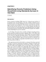
and Matula (1994) developed an automated atomized water spray system (Fig. 3)
capable of delivering steady average fluxes down to about 0.1 mm d
Ϫ1
, which was
considered the minimum flux density needed for hydrological applications (crite-
rion F3).
In this system, water and air are mixed in a nozzle assembly to produce an
atomized water spray. By decreasing the water pressure and increasing the air
pressure, a minimum continuous uniform water spray of about 200 mm d
Ϫ1
has
been obtained. The average water application rate can be reduced further by spray-
ing intermittently under control of a timer with independent ON and OFF periods.
Figure 3 shows the spray system in the laboratory set up for 20-cm diameter soil
columns. The soil columns are placed on very fine sand that can be maintained at
200 Dirksen
Fig. 3 Laboratory setup of atomized water spray system for 20-cm diameter soil col-
umns, with very fine sand box and hanging water column, and tensiometry and TDR
equipment.
Copyright © 2000 Marcel Dekker, Inc.
constant pressure heads of minimally Ϫ120 cm water by means of a hanging water
column with overflow. With proper protection of the exposed sand surface, the
discharge from the overflow is a measure of the flux density out of the soil column.
Hydraulic heads are measured with a sensitivity of 1 mm water at 5 cm depth
intervals. Water contents are measured with 3-rod TDR sensors installed halfway
between and perpendicular to the tensiometers. Thus all the accuracy-enhancing
features are present.
Figure 4 shows the hydraulic conductivities as function of water content
measured in a (Typic Hapludoll) soil column. The water flux density was easily
varied over more than three orders of magnitude from virtual saturation (h ϭ
Ϫ0.9 cm) to an average flux density of 0.22 mm d
Ϫ1
, attained with 0.1% actual
spraying time. After this lowest application rate was discontinued, hydraulic heads
changed within two days to essentially hydrostatic equilibrium with the sand, in-
dicating that this low water application rate had indeed produced steady down-
ward flow. In the intermediate range, the discharge from the sand agreed exactly
with the applied water flux densities. The time needed to attain steady state varied
from about one hour at the highest water application rate to about four days at the
lowest rate.
The atomized water spray setup has been tested successfully under field
conditions, using a gasoline-powered 220 VAC electric generator. If 12 VDC
Unsaturated Hydraulic Conductivity 201
Fig. 4 Hydraulic conductivity as a function of volumetric water content, for a Typic
Hapludoll measured with the setup shown in Fig. 3.
Copyright © 2000 Marcel Dekker, Inc.
solenoid valves and a compressed-air cylinder are used, measurements could
be made in situ without an electric generator. After months of inoperation, the
assembly can be started up almost instantaneously without problems of clog-
ging. It has proven to be a reliable, versatile apparatus for measuring quickly and
accurately any soil hydraulic conductivity from that near saturation to about
0.1 mm d
Ϫ1
. The flux densities, and thus the hydraulic conductivities, are predict-
able. These features make it very attractive to incorporate this flux-controlled sys-
tem into a standard method.
C. Steady Rate
An early flux-controlled variant is the so-called Long Column Infiltration method.
By applying a constant flux density to the soil surface of a long, vertical (dry)
soil column (Childs and Collis-George, 1950; Wesseling and Wit, 1966; Childs,
1969), the potentials on both ends of the flow system approach constant values,
while the distance between them increases with time. If the pressure head gradient
becomes negligible with respect to the constant gravitational potential gradient
before the wetting front reaches the bottom of the column, a ‘‘quasi-steady’’ state
will be attained in which the infiltration rate approaches a steady value. During
this ‘‘steady-rate’’ condition, the upper part of the column automatically ap-
proaches the water content at which the hydraulic conductivity is equal to the
externally imposed, known flux density. Thus if that water content is measured,
tensiometers are not needed, and the method can theoretically be used beyond the
tensiometer range. As long as there is still dry soil in the bottom of the column,
porous plates are not needed, and problems with plate and contact resistances are
eliminated. When the wetting front reaches the bottom of the soil column, water
can exit only after it reaches zero suction (water table). This limits the range of
pressure heads and water contents that can be covered, unless there is a (negative)
head-controlled boundary at the bottom of the column. Youngs (1964) applied
water directly at constant pressure head to a long soil column.
D. Regulated Evaporation
Steady state can also be attained when water from a water table or a supply at
constant negative pressure head is evaporated at the soil surface at a constant rate.
Under these conditions of regulated evaporation, there is no measuring zone with
a uniform pressure head and water content. The water content, and thus the hy-
draulic conductivity, decreases towards the surface. Since at steady state the flux
density is everywhere the same, the hydraulic gradient is inversely proportional to
the hydraulic conductivity and thus will become larger and more difficult to mea-
sure accurately towards the soil surface. The hydraulic conductivity obtained will
202 Dirksen
Copyright © 2000 Marcel Dekker, Inc.
be some kind of average for the range of water contents, and the correct water
content to which it should be assigned will be uncertain.
A slightly different experimental arrangement was used by Gardner and
Miklich (1962). Their soil column was closed at one end, which makes it theo-
retically impossible ever to reach a steady state. Nevertheless, they claimed that
various constant fluxes could be attained by regulating the evaporation from the
column by the size and number of perforations in a cover plate. This would seem
to require a lot of manipulation. The rates of water loss were determined by weigh-
ing the column. The hydraulic gradient was measured with two tensiometers. By
assuming k and u were constant between the tensiometers for each evaporation
rate, they derived an approximate equation for the hydraulic conductivity. The
rather severe assumptions limit the applicability of the method and it has not been
frequently used.
E. Matric Flux Potential
A controlled evaporative flux from a short soil column in which the pressure
head at the other end is controlled (previous section) was used by Ten Berge
et al. (1987) in a steady-state method for measuring the matric flux potential as
function of water content. They assumed that the matric flux potential function
has the form
A u
f[u] ϭϪ for x ϭ 1 Ϫ (8)
x ϩ B u
0
where A is a scale factor (m
2
s
Ϫ1
) and B is a dimensionless shape factor, both
typical for a given soil, and u
0
is a reference water content, experimentally con-
trolled at the bottom of the soil column. Whereas these authors used the diffusivity
function proposed by Knight and Philip (1974),
Ϫ2
D[u] ϭ a(b Ϫ u) (9)
where a and b are constants, the method can be used with any set of two-parameter
functions of f[u] and D[u].
After a small soil column is brought to a uniform water content (pressure
head) and weighed, it is exposed to artificially enhanced evaporation at the top,
while the bottom is kept at the original condition with a Mariotte-type water
supply. When the flow process has reached steady state, the flux density is mea-
sured, as well as the wet and oven dry weights of the soil column. From these
simple, accurate experimental data the parameters A and B, and thus f[u] and
D[u], can be evaluated by assuming that gravity can be neglected. In this case the
matric flux potential at steady state decreases linearly with height so that this
method does not suffer from any ambiguity (generally associated with upward
Unsaturated Hydraulic Conductivity 203
Copyright © 2000 Marcel Dekker, Inc.
flow) in the assignment of appropriate values of water content and pressure head
to the calculated values of the water transport parameter.
It is better not to start from saturation, but at a small negative pressure head,
to reduce the influence of gravity and to be able to meet the theoretically required
upper boundary condition (u ϭ 0). The method is rather slow and covers a limited
range of u and h, but the measurements require little attention while in progress.
The major source of errors appears to be that the theoretically prescribed initial
and boundary conditions are hard to obtain experimentally. Furthermore, the theo-
retical basis involves a number of assumptions. However, direct measurement of
f[u] is likely to be more accurate than methods involving separate measurements
of h[u] and D[u] for flow processes involving steep gradients such as thin, brittle
soil layers. For an analysis of the propagation of errors, see Ten Berge et al.
(1987).
VII. STEADY-STATE FIELD METHODS
A. Sprinkling Infiltrometer
Analogous to the measurements in long laboratory soil columns (Sec. VI.C), hy-
draulic conductivities can be measured in the field under steady-rate conditions
delivered by a sprinkling infiltrometer (Hillel and Benyamini, 1974; Green et al.,
1986). It is the counterpart to the flux-controlled atomized spray laboratory setup
(Sec. VI.B) and appears to be the best candidate for ‘‘standard field method.’’ In
such applications, elaborate sprinkling equipment, which must normally be at-
tended whenever in operation, is justified. Measurements may extend over days or
even weeks, depending on the range of water contents to be covered. This range
is technically limited by the ability to reduce the sprinkling rate while retaining
uniformity. This can be done best by intercepting an increasing proportion of the
artificial rain, rather than reducing the discharge from a nozzle (Amerman et al.,
1970; Rawitz et al., 1972; Kleijn et al., 1979). Green et al. (1986) give 1 mm h
Ϫ1
as a practical lower limit for the flux density. To prevent hysteresis, the flux den-
sity of the applied water should be increased monotonically with time. Because
soil profiles are frequently inhomogeneous, and because of possible lateral flow,
the hydraulic gradient cannot be assumed to be unity, and it should be measured
when a high accuracy is required. Sprinkling infiltrometers are used frequently for
soil erodibility studies. In such applications, the impact energy of the water drops
emitted by the sprinkling infiltrometer should be as nearly equal to that of natural
rain drops as possible (Petersen and Bubenzer, 1986), since changes of the soil
physical properties due to structural breakdown (e.g., crust formation) have a
great effect on the erosion process (Baver et al., 1972; Lal and Greenland, 1979).
For hydraulic conductivity measurements, in contrast, the soil surface should be
204 Dirksen
Copyright © 2000 Marcel Dekker, Inc.
protected against crust formation as much as possible (e.g., by covering the soil
surface with straw).
Field measurements of hydraulic conductivity with a sprinkling infiltro-
meter may take a long time, during which large temperature variations may occur.
Temperature changes and gradients may have a significant influence on the water
transport process, especially for small water flux densities and/or hydraulic head
gradients near the soil surface. Therefore it is good practice to ensure that all field
measurements minimize temperature changes as much as possible (e.g., by shield-
ing the soil surface from direct sunlight).
B. Isolated Soil Column with Crust
Instead of applying water over a large soil surface and concentrating the measure-
ments in the center of the wetted area to approach a one-dimensional flow system
(preceding Sec.), true one-dimensionality can be obtained in situ by carefully ex-
cavating the soil around a soil column (Green et al., 1986; Dirksen, 1999, Fig. 8.1).
Although not strictly necessary for unsaturated conditions, a plaster of Paris jacket
is usually cast around the ‘‘isolated’’ soil column assembly for protection or for
saturated conductivity measurements. Use of such truly undisturbed soil columns
is especially suitable for soils with a well-developed structure, since large-scale
‘‘undisturbed’’ samples, which are easily damaged during transport, would other-
wise be required. The isolated soil column in its jacket may also be broken off its
pedestal and transported to the laboratory for (additional) measurements.
Water has been applied to such soil columns via crusts of different hydraulic
resistance, usually made of mixtures of hydraulic cement and sand (Bouma et al.,
1971; Bouma and Denning, 1972). If the space above the crust is sealed off air-
tight, water can be applied to the soil column at constant pressure head regulated
by a Mariotte device. Initially, it was commonly assumed that the crust soon
causes the flux density to become steady at unit hydraulic gradient (Hillel and
Gardner, 1969), so that a single tensiometer just below the crust could provide the
pressure head to be associated with the hydraulic conductivity obtained. However,
the hydraulic head gradient generally does not attain unity and should be mea-
sured with at least two tensiometers. By using different values of the controlled
pressure head and/or crust resistance, a number of points on the k[h] function can
be obtained. In practice, the minimum pressure head that can thus be attained
appears to be about Ϫ50 cm.
In comparison with ponding infiltration, the claim that crusts enhance the
attainment of a steady flux is correct, but I suspect that often the final measure-
ments are made before a steady-rate condition has been reached. If measurements
are made at a range of pressure heads, one should proceed from dry to progres-
sively wetter conditions (by replacing more resistant crusts with progressively less
Unsaturated Hydraulic Conductivity 205
Copyright © 2000 Marcel Dekker, Inc.
resistant ones), since a wetter wetting front will quickly overtake a preceding dryer
one. Letting the soil dry before applying a smaller flux density takes much time
and introduces hysteresis into the measurements. The latter is unacceptable if the
obtained hydraulic conductivities are related only to the pressure head. Crust re-
sistances have proved to be quite unpredictable, often nonuniform, and unstable
in time. Making and replacing good crusts is tedious work, and curing takes at
least 24 hours. Crusts may also add to the soil solution chemicals that alter the
hydraulic conductivity. I advocate, therefore, that the ‘‘crust method’’ no longer
be used.
C. Spherical Cavity
In one dimension, steady state can be achieved under two types of steady bounda-
ries, either potentials or flux densities. In the field, it is not too difficult to force
the flow to be one-dimensional by isolating a small cylindrical soil column (pre-
vious Sec.) or a large rectangular soil block. The latter can be done easily by
excavating (preferably with a mechanical digger) narrow vertical trenches, cov-
ering the inside vertical walls with plastic sheets and refilling the trenches with
soil. However, a major experimental effort is required to impose a steady bound-
ary condition at the bottom of a flow system in the field. The practical alternative
of a constant-shape wetting front moving downward at a steady rate in the center
of a large wetted area (Sec. VI.C) can be attained only in a uniform soil profile
that is deep enough for the pressure head gradient to become negligible compared
to gravity.
In three-dimensional flow, the influence of gravity is much smaller than in
one- or two-dimensional flow. As a result, three-dimensional infiltration from
a point source reaches a large-time steady-rate condition irrespective of the influ-
ence of gravity (Philip, 1969). Without gravity, three-dimensional infiltration from
a point source is spherically symmetric. Raats and Gardner (1971) showed that
the hydraulic conductivity can be derived from a series of such steady-rate condi-
tions in which the pressure heads also approach steady values. This presents a
very attractive set of conditions for measuring hydraulic conductivity, especially
in situ, because (1) only one controlled boundary is required, (2) the influence of
gravity, which must be neglected, is especially small, and (3) steady-rate and
steady tensiometer measurements are inherently accurate. For these reasons, I
have explored the possibilities of this ‘‘spherical cavity’’ method and have ana-
lyzed the influence of gravity (Dirksen, 1974).
Water is supplied to the soil (which needs to be initially at uniform pressure
head) through the porous walls of a spherical cavity maintained at a constant pres-
sure head until both the flux Q and the pressure head h
a
, at the radical distance
r ϭ a from the center of the spherical cavity, have become constant. This is re-
206 Dirksen
Copyright © 2000 Marcel Dekker, Inc.
peated for progressively larger (less negative) controlled pressure heads in the
cavity. Hydraulic conductivity can then be calculated according to
1 dQ
k[h ] ϭ (10)
r
rdh
r
which is simply the slope of the graphs in Fig. 5 at any desired pressure head,
divided by the radial distance of the particular measuring point. In this way hy-
draulic conductivities down to h ϭϪ700 cm were obtained in about 2 weeks,
with each tensiometer and the cavity yielding its own result. This overlap provides
an internal check. Note that the pressure head range can be expanded downward
easily by increasing the radial distance of the measuring point. Of course, the time
required to attain a constant pressure head increases with radial distance. It is
possible to use the regulated pressure head in the cavity as the only ‘‘tensiometer’’
data. This reduces the experimental duration and operations to a minimum. The
resistance between the water supply and the soil (porous walls and soil– ceramic
interface) must then be negligible. The effect of gravity is minimized when ten-
siometers, if used, are placed directly below the cavity. The method has been dem-
onstrated only in the laboratory, although there have been some exploratory mea-
surements in the field. Because of its very attractive features, especially as an in
situ method, the approach is worthy of further investigation. If tensiometer mea-
Unsaturated Hydraulic Conductivity 207
Fig. 5 Steady fluxes from a spherical cavity versus steady pressure heads in the cavity
and in three tensiometers at the radial distances indicated. (From Dirksen, 1974.)
Copyright © 2000 Marcel Dekker, Inc.