Mobile Robots book 2011 Part 6 ppsx
Bạn đang xem bản rút gọn của tài liệu. Xem và tải ngay bản đầy đủ của tài liệu tại đây (2.45 MB, 25 trang )
Mobile Robots - State of the Art in Land, Sea, Air, and Collaborative Missions116
4.3 Body with Massive Network of Sensors
A human being’s body is not only agile in performing motions, but also sensible in
capturing visual, auditory, kinesthetic, olfactory, taste, and thermal signals. Most
importantly, a human being’s body is a massive network of sensors. Such a massive sensing
capability helps simplify the complexity of decison-making in undertaking appropriate
actions in response to sensed signals.
Due to cost, today, it is still difficult to develop a humanoid robot which is as sensible as a
human beings.
4.4 Behavioral Control
A human being can perform a wide range of manipulation tasks through the execution of
motions by his/her arms and hands. Hence, it is clear that the motions at the joints of hands
and arms are dictated by an intended task. In industrial robotics, it is well-understood that
the inputs to the motion control loops at the joint level come from a decision-making process
started with an intended task of manipulation. And, such a decision-making process
includes:
z Behavior selection among the generic behaviors of manipulation as shown in Figure
12(a).
z Action selection among the generic actions of manipulation as shown in Figure 12(b).
z Motion description for a selected action.
Fig. 12. Generic behaviours and actions for manipulation.
On the other hand, in the effort toward the design of planning and control algorithms for
biped walking, not enough attention has been paid to this top-down approach of behavioral
control. For instance, a lot of works is focused on the use of ZMP (i.e. zero-moment point) to
generate, or control, dynamically stable gaits. Such stability-centric approaches do not
answer the fundamental question of how to walk along any intended trajectory in real-time
and in real environment. Because of the confusion on the relationship between cause and
Biologically-Inspired Design of Humanoids 117
effect, one can hardly find a definite answer to the question of how to reliably plan and
control a biped walking robot for any real application.
Here, we advocate the top-down approach to implement the behavioral control for biped
locomotion. And, the inputs to the decision-making process for biped walking can be one, or
a combination, of these causes:
z Locomotion task such as traveling from point A to point B along a walking surface.
z Self-intention such as speed-up, slow-down, u-turn, etc.
z Sensory-feedback such as collision, shock, impact, etc.
The presence of any one of the above causes will invoke an appropriate behavior and action
(i.e. effect) to be undertaken by a humanoid robot’s biped mechanism. And, the mapping
from cause to effect will be done by a decision-making process, which will also include:
z Behavior selection among the generic behaviors of a biped mechanism as shown in
Figure 13(a).
z Action selection among the generic actions of a leg shown in Figure 13(b).
z Motion description for a selected action.
Fig. 13. Generic behaviours and actions for biped locomotion.
In order to show the importance of top-down approach for behavioral control, we would
like to highlight the following correct sequence of specifying the parameters of walking:
z Step 1: To determine the hip’s desired velocity from task, intention, or sensory
feedback.
z Step 2: To determine the step length from the knowledge of the hip’s desired velocity.
z Step 3: To determine the walking frequency (i.e. steps per unit of second) from the
knowledge of the hip’s desired velocity and the chosen step length.
In the above discussions, the motion description inside a behavioral control is to determine
the desired values of joint positions, joint velocities, and/or joint torques, which will be the
inputs to the automatic control loops at the joint level, as shown in Figure 14.
Mobile Robots - State of the Art in Land, Sea, Air, and Collaborative Missions118
Fig. 14. Interface between behavioural control and automatic control.
4.5 Cognitive Vision
The behavioral mind of a humanoid robot will enable it to gain the awareness of its stability,
and the awareness of its external disturbance. However, a human being is able to
autonomously and adaptively perform both manipulation and location in a dynamically
changing environment. Such an ability is quite unique due to a human being’s vision which
is intrinsically cognitive in nature.
In engineering terms, if we will design a humanoid robot with the innate ability of gaining
the awareness of its workspace and/or walking terrain, it is necessary to discover the
blueprint behind a cognitive vision and to implement such a blueprint onto a humanoid
robot.
4.6 Cognitive Linguistics
Human beings can communicate effectively in using a natural language. And, the
instructions to human beings can be conveyed in both written and spoken languages. In
engineering terms, such a process of instructing a human being on what to do is very much
similar to programming. But, this type of programming is at the level of a natural language.
This is why it is called a linguistic programming. And, the purpose of linguistic
programming is to make a human being to be aware of next tasks that he or she is going to
perform.
Today, it is still a common practice for a human being to master a machine language in
order to instruct a robot or machine on what to do. Clearly, this process of using machine
language in order to communicate with robots has seriously undermined the emergence of
humanoid robots in a home environment. In near future, it is necessary to design a
humanoid robot which incorporates the blueprint of cognitive linguistics (yet to be
discovered) so that it can gain the awareness of next tasks through the use of natural
languages.
Biologically-Inspired Design of Humanoids 119
5. Implementations
5.1 Appearance and Inner Mechanisms
Our LOCH humanoid robot has the appearance and inner mechanisms as shown in Figure
15. And, the general specifications of the robot body are given in Table 1.
Fig. 15. LOCH humanoid robot: a) appearance and b) inner mechanisms.
Body weight: 80 kg
Body height: 1.75 m
Body width: 0.60 m
Body depth: 0.25 m
Table 1. Specifications of body.
5.2 Robot Head
The primary function of robot head is to sense the environment in which a humanoid robot
is going to perform both manipulation and location. In our design, we have incorporated
four types of environmental sensing capabilities, namely: a) monocular vision, b)
stereovision, c) distance finder (up to 200 meters) and d) laser range finder (within 4 meters).
Figure 16a shows the CAD drawing of the robot head, while the real prototype without
external cover is shown in Figure 16b. And, the specifications of the robot head are listed in
Table 2.
Mobile Robots - State of the Art in Land, Sea, Air, and Collaborative Missions120
Fig. 16. Head of LOCH humanoid robot: a) CAD model and b) actual prototype.
Weight: 4 kg
Height: 22 cm
Width: 25 cm
Depth: 25 cm
Degrees of
Freedom:
z Two DOFs at the neck (Yaw +
Pitch)
Sensors z One PTZ camera
z Two stereo cameras
z One distance finder
z One laser range finder
z Absolute encoder at each neck
joint
Actuators: z Two DC brush motors
z Two low-power amplifiers
z One micro-controller
Functions z Visual perception
z Nod
z Gaze
Table 2. Specifications of Robot Head
5.3 Robot Trunk
The primary function of robot trunk is to house the host computers and power units. In
addition, the robot trunk has two degrees of freedom which enable a humanoid robot to
turn left and right, and also to swing left and right.
In Figure 17, we can see both the CAD model of the robot trunk and the real prototype of
the robot trunk. And, the specifications of robot trunk are listed in Table 3.
Biologically-Inspired Design of Humanoids 121
Fig. 17. Trunk of LOCH humanoid robot: a) CAD model and b) actual prototype.
Height: 58 cm
Width: 40 cm
Depth: 20 cm
Weight: 24 kg
Computing Units: z Two PC104
z One wireless hub
Power Units: z Capacity: 20 AH at 48 VDC
z Current: 20 A
z Voltage: 5V, 12V, 24V and 48V
z Weight: 15 kg
Degrees of
Freedom:
z Two DOFs at the waist (Yaw +
Roll)
Sensors: z One 3-axis GYRO/Accelerometer
z Three microphones
Actuators z Two DC brush motors
z Two low-power amplifiers
z One microcontroller
Functions z Torso turn
z Torso swing
Table 3. Specifications of robot trunk.
5.4 Arms and Hands
Arms and hands are very important to a humanoid robot if it will perform human-like
manipulation. And, the design of arms and hands should enable a humanoid robot to
achieve these five generic manipulation behaviors: a) grasp, b) push, c) pull, d) follow and e)
throw.
In Figure 18, we show both the CAD model and the real prototype of LOCH humanoid
robot’s arms and hands. We can see that LOCH humanoid robot has human-like hands,
each of which has five fingers. And, the specifications of arms and hands are shown in Table
4.
Mobile Robots - State of the Art in Land, Sea, Air, and Collaborative Missions122
Figure 18. Arms and hands of LOCH humanoid robot: a) CAD model and b) actual
prototype.
Length: z Upper arm: 32 cm
z Forearm: 28 cm
z Hand: 16 cm
Weight: z Upper arm: 2.0 kg
z Forearm: 2.5 kg
z Hand: 1.8 kg
Degrees of
Freedom:
z 3 DOFs in shoulder
z 1 DOF in elbow (Pitch)
z 2 DOFs in wrist (Pitch + Roll)
z 2DOFs in the thumbs
z 2 DOF in other fingers (one DOF is passive)
Sensors: z 6-axis force/torque sensor at each wrist
z Absolute encoder at each arm joint
z Potentiometer at each hand joint
z Incremental encoder at each joint
z Pressure sensors at palm and fingers
Actuators: z Six DC brush motors for each arm
z Six DC brush motors for each hand
z Six low-power amplifiers for each arm
z Six low-power amplifiers for each hand
z Three microcontrollers for each arm
z Three microcontrollers for each hand
Biologically-Inspired Design of Humanoids 123
Functions: z Grasp
z Pull
z Push
z Move
z Throw
z Hand-shaking
z Hand gesture
z Handling soft objects
Table 4. Specifications of robot arms and hands.
5.5 Legs and Feet
Legs and feet are unique features which differentiate a humanoid robot from an industrial
robot. And, it is also very important to design legs and feet so that a humanoid robot could
perform human-like biped walking/standing.
In Figure 19, we show both the CAD model and the real prototype of LOCH humanoid
robot’s legs and feet. It is worthy noting that LOCH humanoid robot has a ZMP joint in each
joint, which is implemented by a six-axis force/torque sensor. This ZMP joint allows the
control of the so-called in foot ZMP for leg stability (Xie et al, 2008). And, the specifications
of arms and hands are shown in Table 5.
Figure 19. Legs and feet of LOCH humanoid robot: a) CAD model and b) actual prototype.
Length: z Thigh: 42 cm
z Shank: 42 cm
z Foot: 31 cm
Weight: z Thigh: 8.0 kg
z Shank: 6.0 kg
z Foot: 2.2 kg
Mobile Robots - State of the Art in Land, Sea, Air, and Collaborative Missions124
Degrees of
Freedom:
z 3 DOFs in each hip joint
z 1 DOF in each knee joint (Pitch)
z 2 DOFs in each ankle joint (Pitch + Roll)
z 1 DOF in each foot
Sensors: z 6-axis force/torque sensor below each ankle joint
z Absolute encoder at each joint
z Incremental encoder at each joint
z Six pressure sensors below each foot
Actuators: z Five DC brushless motors for each leg
z One DC brush motor for hip yaw
z One DC brush motor for each foot
z Five high-power amplifiers for each leg
z One low-power amplifier for hip yaw
z One low-power amplifier for each foot
z Four microcontrollers for each leg/foot
Functions: z Foot-hold
z Leg support
z Leg carry
z Leg push
z Leg swing
z Standing
z Sitting
z Stepping
z Walking
z Running
z Climbing
z Crawling
z Entering/exiting car
Table 5. Specifications of robot legs and feet.
6. Discussions
A good design will enable a sophisticated analysis, control and programming of a
humanoid robot.
6.1 Kinematics
In terms of analysis, two important aspects are kinematics and dynamics. As a humanoid
robot can be treated as an open kinematic chain with bifurcation, the tools for analysing
industrial arm manipulator are applicable to model the kinematics of a humanoid robot
(Xie, 2003).
However, one unique feature with a humanoid robot is that there is no fixed base link for
kinematic modelling. Therefore, an interesting idea is to describe the kinematics of a
humanoid robot with a matrix of Jacobian matrices. For instance, if a humanoid robot has N
coordinate systems assigned to N movable links, a NxN matrix of Jacobian matrices is
Biologically-Inspired Design of Humanoids 125
sufficient enough to fully describe the kinematic property of a humanoid robot. And, in
Figure20,
ij
J
refers to the Jacobian matrix from link i to link
j
.
Fig. 20. A matrix of Jacobian matrices to describe the kinematics of a humanoid robot.
6.2 Dynamics
Given an open kinematic chain, the dynamic behaviour can be described by the general
form of differential equation as shown in Figure21.
However, biped walking is not similar to manipulation. As a result, a common approach is
to simplify a biped mechanism into a model called linear inverted pendulum. And, a better
way to understand inverted pendulum model is the illustration by the so-called cart-table
model (Kajita et al, 2003).
Mobile Robots - State of the Art in Land, Sea, Air, and Collaborative Missions126
Fig. 21. General dynamic equation of an open kinematic chain.
Here, we believe that we can treat a leg as an inverted arm with the foot to serve as the base
link. In this case, the leg supporting the upper body of a humanoid robot is undergoing a
constrained motion. And, it has both horizontal and vertical dynamics as shown Figure22.
Fig. 22. Inverted arm model to describe the dynamics of a biped mechanism.
In Figure22, we assume that a leg has a six degrees of freedom. J is the Jacobian matrix of a
leg.
P
is the hip’s velocity vector and Q
is the vector of the joint velocities of the leg. And,
m
is the mass of a humanoid robot’s upper body.
Biologically-Inspired Design of Humanoids 127
6.3 Human-Aided Control
Today’s robots still have limited capabilities in gaining the situated awareness through
visual perception and in making meaningful decisions. Therefore, it is always useful to
design a humanoid robot in such way that a human operator can assist a humanoid robot to
perform complex behaviours of manipulation and/or biped walking.
Therefore, it is interesting to implement virtual versions of a real humanoid robot, which
serve as the intermediate between a human operator and a real humanoid robot, as shown
in Figure23.
Fig. 23. Human-aided control through the use of virtual robots.
Refer to Figure 23. A human operator could teach a virtual robot to perform some intended
tasks. Once a virtual robot has mastered the skill of performing a task, it will instruct the
real robot to perform the same task through synchronized playback. On the other hand, a
virtual robot could also play the role of relaying the sensory data of a real humanoid robot
back to a human operator so that he/she will feel the sensation of interaction between a
humanoid robot and its working environment.
7. Summary
In this chapter, we have first highlighted some characteristics observed from human abilities
in performing both knowledge-centric activities and skill-centric activities. Then, we apply
the observations related to a human being’s body, brain and mind to guide the design of a
humanoid robot’s body, brain and mind. After the discussions of some important
considerations of design, we show the results obtained during the process of designing our
LOCH humanoid robot. We hope that these results will be inspiring to others.
Mobile Robots - State of the Art in Land, Sea, Air, and Collaborative Missions128
8. Acknowledgements
The authors would like to thank the project sponsor. In particular, the guidance and advices
from Lim Kian Guan, Cheng Wee Kiang, Ngiam Li Lian and New Ai Peng are greatly
appreciated. Also, we would like to thank Yu Haoyong, Sin Mong Leng and Guo Yongqiang
for technical support. Supports and assistances from Zhong Zhaowei, Yang Hejin, Song
Chengsen and Zhang Li are gratefully acknowledged.
9. References
Xie, M.; Zhong, Z. W.; Zhang, L.; Xian, L. B.; Wang, L.; Yang, H. J.; Song, C. S. & Li, J. (2008).
A Deterministic Way of Planning and Controlling Biped Walking of LOCH
Humanoid Robot. International Conference on Climbing and Walking Robots.
Xie, M.; Dubowsky, S.; Fontaine, J. G.; Tokhi, O. M. & Virk, G. (Eds). (2007). Advances in
Climbing and Walking Robots, World Scientific.
Bruneau, O. (2006). An Approach to the Design of Walking Humanoid Robots with
Different Leg Mechanisms or Flexible Feet and Using Dynamic Gaits. Journal of
Vibration and Control, Vol. 12, No. 12.
Kim, J.; Park, I.; Lee, J.; Kim, M.; Cho, B. & Oh, J. (2005). System Design and Dynamic
Walking of Humanoid Robot KHR-2. IEEE International Conference on Robotics and
Automation.
Ishida, T. (2004). Development of a Small Biped Entertainment Robot QRIO. International
Symposium on Micro-Nanomechatronics and Human Science, pp23-28
Xie, M.; Kandhasamy, J. & Chia, H. F. (2004). Meaning Centric Framework for Natural
Text/Scene Understanding by Robots, International Journal of Humanoid Robotics,
Vol. 1, No. 2, pp375-407.
Xie, M. (2003). Fundamentals of Robotics : Linking Perception to Action. World Scientific.
Kajita, S. ; Kanehiro, F. ; Kaneko, K. ; Fujiwara, K. ; Harada, K. ; Yokoi, K. & Hirukawa, H.
(2003). Biped Walking Pattern Generation by Using Preview Control of Zero-
Moment Point, IEEE International Conference on Robotics and Automation.
Sakagami, Y. ; Watanabe, R. ; Aoyama, R. ; Matsunaga, C. ; Higaki, S. & Fujimura, K. (2002).
The Intelligent ASIMO : System Overview and Integration. IEEE International
Conference on Intelligent Robots and Systems, pp2478-2483.
Espiau, B. & Sardain, P. (2000). The anthropomorphic Biped Robot BIPED2000. IEEE
International Conference on Robotics and Automation, pp3996-4001.
Hirai, K. ; Hirose, M. ; Hikawa, Y. & Takanaka, T. (1998). The Development of Honda
Humanoid Robot. IEEE International Conference on Robotics and Automation.
Zhu, H. H. ; Xie , M. & Lim, M. K. (2000). Modular Robot Manipulator Apparatus. PCT
Patent Application, No. PCT/SG00/00002.
Kaneko, K. ; Kanehiro, F. ; Yokoyama, S. ; Akachi, K. ; Kawasaki, K. ; Ota, T. & Isozumi, T.
(1998). Design of Prototype Humanoid Robotics Platform for HRP. IEEE
International Conference on Intelligent Robots and Systems, pp2431-2436.
7
The State-of-Art of Underwater Vehicles
– Theories and Applications
W.H. Wang
1
, R.C. Engelaar
2
, X.Q. Chen
1
& J.G. Chase
1
1
University of Canterbury, New Zealand
2
University of Technology, Eindhoven, Netherlands
1. Introduction
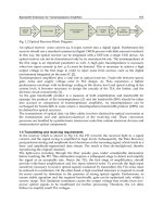
An autonomous underwater vehicle (AUV) is an underwater system that contains its own
power and is controlled by an onboard computer. Although many names are given to these
vehicles, such as remotely operated vehicles (ROVs), unmanned underwater vehicles
(UUVs), submersible devices, or remote controlled submarines, to name just a few, the
fundamental task for these devices is fairly well defined: The vehicle is able to follow a
predefined trajectory.
AUVs offer many advantages for performing difficult tasks submerged in water. The main
advantage of an AUV is that is does not need a human operator. Therefore it is less
expensive than a human operated vehicle and is capable of doing operations that are too
dangerous for a person. They operate in conditions and perform task that humans are not
able to do efficiently or at all (Smallwood & Whitcomb, 2004; Horgan & Toal, 2006; Caccia,
2006).
First developed in the 1960’s, development was driven by the demand from the US Navy
(Wernli, 2001), which required them to perform deep sea rescue and salvage operations. In
the 1970s, universities, institutes and governmental organizations started with the
experimentation with AUV technology. Some of them were successful, most were not.
Despite this, there was significant advancement in the development of AUVs. Since then,
other sectors have realized the potential of such devices for all manner of tasks. The first of
these was the oil and gas industry. These companies employed AUVs to reinforce in the
development of off shore oil fields (Williams, 2004). In the 1980’s, AUVs came into a new era
as they were able to operate at depths well below commercial diver limits. Falling oil prices
and a global recession resulted in a stagnant period in terms of AUV development in the
mid 1980s. During the 1990s there was a renewed interest in AUVs in academic research.
Many universities developed AUVs. This research was followed by the first commercial
AUVs in 2000 (van Alt, 2000; Blidberg, 2001). Since then, AUVs have been developing at a
fast rate (Smallwood et al., 1999; Griffiths & Edwards, 2003).
AUVs are now being used in a wide range of applications, such as locating historic ship
wrecks like the Titanic (Ballard, 1987), mapping the sea floor (Tivey et al., 1998). More
mundane applications consist of object detection (Kondoa & Ura, 2004), securing harbours,
searching for seamines (Willcox et al., 2004), and, most recently, in scientific applications
Mobile Robots - State of the Art in Land, Sea, Air, and Collaborative Missions130
(Curtin & Bellingham, 2001; Rife & Rock, 2002; Lygouras et al., 1998). In the past few years,
advances in battery design and manufacture have led to batteries with high power densities,
which have significantly increased the endurance of AUVs (Wilson & Bales, 2006). At the
same time, the development of new technologies made the AUVs more accurate.
This book chapter aims to highlight theories and applications of technologies that are
suitable for AUVs by literature review and a detailed AUV design. The chapter is therefore
organized as follows. Firstly, Sections 2-6 provide an overview of the latest developments of
five different subjects of an AUV, including: 1) the structure of AUVs; 2) controls and
navigation; 3) propulsion, drive and buoyancy; 4) sensors and instrumentation of AUVs;
and 5) power supply of AUVs. Next, Section 7 reports a relatively low-cost AUV recently
developed at the University of Canterbury for shallow waters. Finally, future work and
conclusions are given in Section 8.
2. Structure of AUVs
One of the most important aspects of an AUV is the hull. There are a number of different
ways in which hull design can be approached (Allmendinger, 1990). These different design
methods are typically specific to the situation/task. The main hull must be able to meet a
number of key challenges.
Aspects that must be considered during hull design include:
x Pressure and/or depth required
x Operating temperature ranges
x Structural integrity for additions and tapings
x Impact conditions
x Water permeability
x Visual appeal and aesthetics
x Accessibility
x Versatility
x Practicality
x Restrictions for future additions
x Size requirements
x Corrosion and chemical resistance
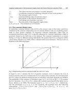
Among these considerations, the hull of the AUV must be able to withstand the hydrostatic
pressure at the target depth. Furthermore, it is desired that the hull is designed in such a
way that the drag is minimized. When the vehicle moves at a constant speed, the thrust
force is equal to the drag force. The less drag the AUV experiences, the less propulsive
power is needed. These two requirements, the ability to withstand the hydrostatic pressure
and the minimization of the drag, are dependent of the shape and size of the vehicle. The
hydrostatic pressure is given by Equation (1).
P = P
a
+
U
gh
(1)
With P the hydrostatic pressure in N/m
2
, P
a
the atmospheric pressure at sealevel in N/m
2
,
U
the density of the water in kg/m
3
, g the gravitational acceleration in m/s
2
and h the depth in
m. The hydrostatic pressure increases with approximately 10
5
N/m
2
per 10 meters. The hull
must be able to withstand this force. A sphere is probably the first shape that comes into
The State-of-Art of Underwater Vehicles – Theories and Applications 131
ones head, it is a good shape for withstanding pressure, but not for stability (Paster, 1986). A
circular cylindrical hull is a good shape to resist the pressure (Ross, 2006). Many of the
current AUVs have a circular cylindrical hull including the most popular in military and
scientific use, the REMUS100 (Hsu et al., 2005; Evans & Meyer, 2004; Maurya et al., 2007).
Some examples are shown in Figures 1. to 3.
Fig. 1. The HUGIN 4500 autonomous underwater vehicle during deployment for sea trials
(Kauske et al., 2007)
Fig. 2. The Cal Poly AUV model (Monteen et al., 2000)
Fig. 3. The Seahorse AUV (Tangirala & Dzielski, 2007)
Some of the advantages of a cylindrical hull are (Ross, 2006):
x It is a good structure to resist the effects of hydrostatic pressure;
x Extra space inside the hull can be achieved by making the cylinder longer;
x It is a better hydrodynamic form than a spherical form of the same volume; and
x It can be easily docked.
Mobile Robots - State of the Art in Land, Sea, Air, and Collaborative Missions132
The disadvantages of a cylindrical hull are the cavitation (Paster, 1986), and the instability of
the vehicle (Ross, 2006). Cavitation is a phenomenon caused by the pressure distribution
generated by the moving vehicle. The difference in local velocity of the body surface results
in a pressure distribution. The point that has the maximum rate of change in curvature of
the body has the negative minimum pressure. If this pressure reaches the vapor pressure of
water, the water will start to boil. The bubbles formed by this boiling collapse when they
reach the point where the pressure increases again. The collapse of the bubbles generates
very high pressure. This leads to high noise levels and the possibility of damaging the
vehicle (Paster, 1986).
Every object that moves in the water experiences drag force. This drag force (in Newton) is
given by Equation (2).
F
dra
g
= 1/2
U
v
2
c
d
S
(2)
With
U
the density of water [kg/m
3
], v the velocity of the vehicle in m/s, c
d
the unitless drag
coefficient of the vehicle and S the surface area of the vehicle normal to the moving direction
in m
2
. The drag coefficient is dependent on the shape of the underwater vehicle. The nose of
the circular cylinder used to be spherical, but this caused instability and cavitation (Paster,
1986). The shape of the nose was finetuned to resemble the front of a teardrop (Paster, 1986).
A good hydrodynamic body shape design will reduce the drag and improves the range of
the vehicle by 2 to 10 times, according to (Paster, 1986).
Another choice that needs to be made in the design phase is the choice for the material of the
hull. The material should have a good resistance to corrosion, have a high strength to weight
ratio and must be affordable. In the past, the most used material was steel. In (Ross, 2006)
four materials are compared; high strength steel, aluminium, titanium and composites.
The advantages of high strength steel are the price and the fact that it is commonly used, so
there is much knowledge of it. The major disadvantage of steel is the low strength to weight
ratio.
Aluminium has a better strength to weight ratio than steel and is widely available. The
drawback of aluminium is that it is anodic to most other structural alloys, making it
vulnerable to corrosion. The strength to weight ratio of titanium is even better than that of
aluminium, but it is an expensive material.
The most commonly used composite for marine vehicles is glass-fiber reinforced plastic
(GFRP). GFRP is cheap with respect to other composites and has a very high strength to
weight ratio. Carbon fiber reinforce composites (CFRP) are about 3 times more expensive
than GFRP, but have a much higher tensile modulus than GFRP. Metal matrix composites
(MMC) have a lot of advantages over GFRP and CFRP but are still in the development
phase, making them very expensive (about 15 times more expensive than GFRP).
Another material that can be used for AUVs is acrylic plastic. Acrylic is already the most
used material for pressure resistant viewports (Stachiw, 2004). The main advantages of
acrylic are that it does not corrode and has a good strength to weight ratio. Furthermore,
acrylic is transparent and there are acrylic submersibles that operate at depths up to 1000
meters below the surface.
The State-of-Art of Underwater Vehicles – Theories and Applications 133
AUVs that have an operating depth of tens of meters can also be constructed of PVC. The
material is widely available and very cheap. With a hull made of PVC it is also easy to
mount components on it (Monteen et al., 2000). Table 1 summarizes the properties of each
material discussed. The specific strength is given by the ratio of the yield strength and the
density.
Material
Density
(kg/dm
3
)
Yield
strength
(MPa)
Tensile modulus
(GPa)
Specific
strength
(kNm/kg)
High strength Steel (HY80) 7.86 550 207 70
Aluminium alloy (7075-6) 2.9 503 70 173
Titanium alloy (6-4 STOA) 4.5 830 120 184
GFRP (Epoxy/S-lass) 2.1 1200 65 571
CFRP (Epoxy/HS) 1.7 1200 210 706
MMC (6061 Al/SiC) 2.7 3000 140 1111
Acrylic 1.2 103 3.1 86
PVC 1.4 48 35 34
Table 1. Material properties, from (Ross, 2006) and (Stachiw, 2004)
According to numerous authors the cylindrical shape is a very good one for an AUV. In the
future MMC may be the best choice for the material, but until then GFRP is a good choice
for AUVs. If the operating depth is only tens of meters, PVC is a good and cheap alternative.
3. Controls and navigation
An AUV must be able to operate autonomously. In order to achieve this it is essential that
the computer in the AUV knows its current location at all time. This can be done by means
of an accurate navigation system. Another reason that the AUV has got to know its location
is because of the fact that gathered data is pretty much useless if the location from which it
has been acquired is unknown (Leonard et al., 1998). To navigate properly a good, accurate
controller is necessary for which first a mathematical model of the AUV is needed. The basic
model for the AUV is described in Equation (3).
W
K
)()()( gDCM vvvvv
v)(
K
K
J
(3)
Where M is the inertia matrices for rigid body and added mass,
K
= [x, y, z,
I
,
T
,
\
]
T
the
position and orientation (Euler angles) in inertial frame,
Q
= [u, v, w, p, q, r]
T
the linear and
angular velocities in body-fixed frame, C is the Coriolis matrix for rigid body and added
mass, D is the quadratic and linear drag matrix, g is the buoyancy and gravity forces,
W
is the
thruster input vector and J is the coordinate matrix which brings the inertial frame into
alignment with the body-fixed frame. The model is described in detail in (Fossen, 1994).
When a model is made for the vehicle it is possible to design a controller. For low speed
vehicles, the horizontal and vertical movements can be decoupled, which makes the model
of the vehicle less complex (Maurya et al., 2007; Williams et al., 2006; Ridao et al., 2001).
Because a single fixed linear controller is not sufficient to deal with all the vehicle dynamics,
a gain-scheduled controller is often used (Kaminer et al., 1995). First, a number of controllers
Mobile Robots - State of the Art in Land, Sea, Air, and Collaborative Missions134
are designed for a finite number of linearized models using H
f
-control. H
f
-control rests on a
good theoretical basis and offers clear guidelines to achieve robust performance in the case
of uncertainties in the plant (Zeng & Allen, 2004; Fryxell et al., 1996). These controllers are
then combined using gain-schedule on some variables, making the overall controller a linear
time-varying system. In multiple articles (e.g. Zeng & Allen, 2004; Jalving, 1994) three
different controllers are designed. One is used to control the speed, the other for the heading
and the last one for the depth.
In (Valavanis et al., 1997) four different architectures for control are described. The
hierarchical architecture is a top-down approach which uses levels. The higher levels are
responsible for overall mission goals, while the lower levels solve particular problems. It has
a serial structure, which means that the higher levels send commands to lower levels. It is a
well-defined structure, but has a lack of flexibility. The heterarchical architecture is a parallel
structure. It has flexibility and is suitable for parallel processing. However, due to lack of
supervision the communication can be intensive. With the subsumption architecture the
different behaviors work in parallel, however one layer can subsume another layer. This
architecture is robust and exhibits true dynamic reactive behavior. The disadvantage is the
difficulty to synchronize the system.
Finally, the hybrid architecture is a combination of the three architectures. It is divided into
two levels. The higher level uses hierarchical architecture while the lower uses either
heterarchical or subsumption to control the hardware. It combines the advantages of the
three architectures and is used in many vehicles (Williams et al., 2006; Valavanis et al., 2997;
Gaccia & Veruggio, 2000). (Gaccia & Veruggio, 2000) makes use of an inner and an outer
control loop. The inner loop is used for the control of the velocity and the outer loop is used
for guidance control and to set the reference velocities.
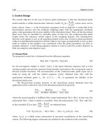
When a controller is designed for the vehicle, the navigation system can be implemented.
According to (Stutters et al., 2008) the accuracy of position estimation will degrade over time
if the position of the AUV is not externally referenced. The lack of easy observable external
references makes AUV navigation very difficult.
Leonard et al. (1998) describes the three primary methods of navigation, dead-reckoning
and inertial navigation systems, acoustic navigation and geophysical navigation techniques.
The sensors and instrumentation used for the measurement of the different variables are
described in Section 5. Dead-reckoning integrates the vehicle velocity in time to obtain the
position. The information is then processed by a Kalman filter which gives an estimate of
the current position. The velocity measurement can be affected by sea currents, so
operations near the seabed use Doppler velocity logs (DVL, see Section 5) to measure the
velocity with respect to the ground. Inertial navigation uses the acceleration of the vehicle
and integrates this twice. This is more accurate then the velocity measurement, but the
initialization can be difficult (Lee et al., 2007).
The problem with both systems is that the position error increases as the distance traveled
increases. This can be solved by surfacing the vehicle from time to time to obtain the correct
position via GPS, but this is not always an option. There are some vehicles, using DVL, that
are accurate to 0.01% of the distance traveled (Leonard et al., 1998).
A typical block diagram of an inertial navigation system is shown in Figure 4. Acoustic
navigations use external transducers which return the acoustic signal send out by the
vehicle. The travel time of the signal determines the position of the vehicle. However,
The State-of-Art of Underwater Vehicles – Theories and Applications 135
reflections and differences in signal speed can negatively influence the measurement.
Geophysical navigation uses a priori knowledge of terrain to identify the current position.
The disadvantage of this system is that the maps of the terrain must exist, and this is not
always the case. It also requires a lot of computational power to find the current position. To
minimize this, the sys tem can be used in combination with dead-reckoning to limit the
search area. The reliability of the system depends on the accuracy of the a priori map. With
concurrent mapping and localization the vehicle builds up a map of its environment and
uses that map to navigate in real time.
Fig. 4. Aided inertial navigation system (Fauske et al., 2007)
For short-range missions, up to 10km, calibrated inertial navigations systems can provide
sufficient accuracy. The system can be extended with a DVL. For longer missions, up to
100km, the path taken by the AUV has a large effect on the accuracy. Concurrent mapping
and localization works well for these missions, as long as the path contains many crossover
points the technique corrects inaccuracies. Above 100km a geophysical navigation system is
the only suitable solution. However, this technique is limited by the availability of maps
(Stutters et al., 2008).
4. Propulsion, dive and buoyancy
The most common form of propulsion is via thrusters. For vertical movement thrusters or
variable buoyancy systems can be used. The thrusters provide more accuracy and a faster
response. If it is not a problem that the vehicle has to move horizontally in order to move
vertically the vehicle can also use a single thruster for both the horizontal and vertical
movement with the use of diving planes or a robotic wrist.
Mobile Robots - State of the Art in Land, Sea, Air, and Collaborative Missions136
The kind of propulsion, the drive and the choice for the buoyancy are of great influence on
the dynamics of the vehicle. There are a lot of choices that have to be made in the design
phase. The horizontal movement of an AUV is usually empowered by thrusters. One of the
reasons for this is that most underwater vehicles are powered by batteries (Smith et al., 1996)
(see Section 6 for more information). In (Valavanis et al., 1997), 25 AUVs are described, of
which the majority use thrusters for propulsion. The vertical movement can be done with
thrusters or by a variable buoyancy system. The buoyancy of an AUV is the upward force
on the vehicle that is caused by the surrounding water. If the buoyancy force is equal to the
gravitational force on the vehicle, the vehicle is said to be neutral buoyant. It will neither
sink nor rise.
When thrusters are used, the vehicle has neutral buoyancy (Serrani & Conte, 1999). The
vehicle is then able to move vertically by using the thrusters. One of the advantages of this
method is that the vehicle is able to hover without propulsion. A disadvantage of the
technique is that the thrusters must remain on will moving vertically, thus consuming
power.
There are four static and dynamic diving principles (Wolf, 2003): i) a piston type ballast tank;
ii) a hydraulic pump based ballast system; iii) an air compressor based system; and iv) direct
thrust systems. The first three concepts come from static diving technology, while the last
concept is a dynamic diving technology.
The piston ballast tank (Figure 5a) is one of the most common static diving methods applied
in submarine modeling. A piston ballast tank consists of a cylinder and a movable piston,
and it works as a large syringe pump. With one end of the cylinder connected to
surrounding water, movement of the piston sucks water in or pushes it out. When water
fills the tank, negative buoyancy is achieved, so the AUV starts to descend. Conversely,
when the tank is emptied, the AUV is positively buoyant, so it ascends. This setup also
allows control of pitch motions of the AUV. Moreover, the pistons can be moved by a linear
actuator, which is electrically easy to control. Hence, accurate depth control can be achieved
with proper, yet straightforward, programming.
A hydraulic pumping system (Figure 5b) is similar to the piston ballast tank, but uses an
internal reservoir of hydraulic fluid and a pump to actuate the piston’s linear motion.
Control of the valves and the pump for the hydraulic fluid allows it to flow in and out of the
cylinders, so the surrounding water can be pumped in and out. Consequently, buoyancy of
the AUV is changed.
Fig. 5. Examples of two diving principles. (a) Piston ballast system with two tanks. (b)
Schematic sketch of hydraulic pumping system
(
a
)
(
b
)
tan
k
tan
k
p
iston
moto
r
The State-of-Art of Underwater Vehicles – Theories and Applications 137
Air compressor systems are commonly used in some classes of submarine. The system is
composed of a storage tank of compressed air, a water tank and two valves that are
normally closed. To descend, the vent valve is opened, so the pressure difference results in
water flowing in from the opening in the bottom of the water tank. When a desired amount
of water is obtained for ballast, the vent valve is closed. In order to force the water out, the
blow valve is opened to allow the compressed air into the tank so that water is pushed out
via the bottom opening. Thus, by letting the water in and out of the water tank, the
buoyancy of the AUV is changed.
Thrusters are a dynamic diving method. They require the AUV to be near neutrally buoyant.
This approach uses the vertically mounted thrusters to force the AUV to dive. Turning off
the thrusters or using them at a thrust less than the positive buoyancy allows controlled
ascent. However, this method consumes a lot of power to keep the AUV under water, as the
thrusters must remain powered at virtually all times. Being positively buoyant, however,
this method is intrinsically failsafe, as the vehicle will come to the surface in the event of a
power failure.
With a variable buoyancy system the vehicle is able to vary its buoyancy. The system
usually contains a number of tanks that can be filled with water or gas. With this system the
vehicle is able to move vertically by changing its buoyancy. Vertical movement and
hovering is then possible without propulsion. The drawback of the system is that it is not as
accurate as using thrusters. In (Tangirala & Dzielski, 2007) a variable buoyancy system is
described that consists of two water tanks with pumps and valves. If more negative
buoyancy is needed, the tanks are open to seawater. If positive buoyancy is needed, the
water is pumped out of the tanks. In (Wasserman, 2003) a vehicle is proposed that uses air to
acquire more positive buoyancy. The vehicle has a tank which can be filled with air coming
from a compressed air tank. Water is drained from the tank when it is filled with air and
more positive buoyancy is generated. There are also vehicles that use only one thruster for
propulsion and do not have a variable buoyancy system (Cavallo & Michelini, 2004; Maurya
et al., 2007). The vehicle described in (Cavallo & Michelini, 2004) uses a robotic wrist to
position the thruster. This enables the vehicle to move horizontally and vertically. The
vehicle is not able to move vertically without moving horizontally; however it is able to do
vice versa. The vehicle described in (Maurya et al., 2007) cannot move vertically either
without moving horizontally (again, vice versa it can), but instead of using a robotic wrist, it
uses diving planes to move vertically.
5. Sensors and instrumentation
As described in Section 3 it is essential for an AUV to know its current position. In order to
calculate that position a number of sensors are necessary. The most common sensor is a
pressure sensor, it is used to measure the external pressure experienced by the vehicle. This
pressure can be converted to a depth (Williams et al., 2006). For dead-reckoning navigation
the vehicle speed is needed. There are numerous ways to measure the speed of the vehicle.
Usually the velocity is measured using a compass and a water speed sensor. In (Modarress
et al., 2007) a sensor is described which can measure the speed of the vehicle using particles
that are present in the water. The speed of the particles is measured with diffractive optic
elements. Small particles pass through two parallel light sheets and scatter light. The
scattered light is collected and the speed of the particles is computed using the time-of-light
Mobile Robots - State of the Art in Land, Sea, Air, and Collaborative Missions138
and the physical separation of the two light sheets. The sensors are small, very accurate and
insensitive for temperature changes and water pressure (Modarress et al., 2007). The
problem with these techniques is that sea currents can add velocity components which are
not detected by the speed sensor (Leonard et al., 1998).
For operations near the seabed, Doppler velocity logs (DVLs) can be used to measure the
vehicle's velocity with respect to the ground. With these measurements the accuracy of the
position estimation by the Kalman filter can improve greatly (Leonard et al., 1998; Lee et al.,
2007). A DVL measures the Doppler shift of sonar signals reflected by the ground to obtain
the velocity (Keary et al., 1999). The system becomes less accurate at low speeds. The
correlation velocity log (CVL) is based on the same principle as the DVL, but emits two
pulses in close succession. The echoes from the seabed are compared and used to calculate
the velocity. This technique is more accurate at low speeds (Keary et al., 1999). Both systems
are not influenced by sea currents.
The inertial navigation system (INS) uses accelerometers and gyroscopic sensors to detect
the acceleration of the vehicle (Stutters et al., 2008). The measurements are not influenced by
sea currents and are therefore more accurate. However, the system is more expensive than
the velocity sensors (Leonard et al., 1998). INSs used to be equipped with mechanical
gyroscopes. The latest INS uses laser gyroscopes or fiber optic gyroscopes that have no
moving parts. This means no friction, leading to more accuracy. In (Fauske et al., 2007)
sensor fusion is used to provide more accuracy to the INS. An error-state Kalman filter
estimates the drift of the inertial sensors, using external information as measurement, e.g. a
DVL and position updates by a mother ship, see Figure 4. With the use of more sensors for a
number of parameters, a higher accuracy is achieved (Majumder et al., 2001).
Another aspect for which sensors are needed is obstacle detection. The vehicle must be able
to detect obstacles before crashing into them. According to (Majumder et al., 2001)
underwater cameras and active sonar are two of the most common sensors for obstacle
detection. (Majumder et al., 2001) also states that there should always be at least two
sensors, because in a sub-sea environment the information from one sensor can be of poor
quality. Therefore, in the technique proposed both the information from the sonar and the
camera are used for obstacle detection. Ultrasonic/acoustic sensor systems allow detection
of objects far beyond the range of video. Current AUVs detect objects with long range sonar.
Lower frequency waves suffer less attenuation in water than higher frequencies. However,
the resolution for imaging sonars is better at higher frequencies (Toal et al., 2005).
In (Toal et al., 2005) a new technique is proposed using optical fibers for object detection.
Two different sensors are used: one provides information without contact, the other
provides information using contact with the object. The first is an extrinsic sensor which
transmits light from the sensor end, if there is an object the light will reflect and received by
a detector. The second sensor is an intrinsic sensor which does not transmits the light but
contains the light within the fiber. A deformation of the fiber, so if the fiber touches an
object, has a detectable effect on the light within the fiber. The vehicle described in (Williams
et al., 2006) has two sonars. One is used for the determination of depth and obstacle
detection. The other is an imaging sonar, which is used to build a map of the environment.
The main sensors for an AUV are a depth sensor, a compass and a speed sensor. With these
sensors the vehicle can estimate its position. It is desirable to equip the vehicle with a
Doppler velocity log to increase the accuracy of the estimates. Inertial navigation systems
The State-of-Art of Underwater Vehicles – Theories and Applications 139
with laser or fiber optic gyroscopes are more expensive but also more accurate than the
standard speed sensors. Sonar, underwater cameras or optical fibers can be used for obstacle
detection.
6. Power supply
As mentioned in Section 1 an AUV must contain its own power. The most common power
supply for AUVs is batteries (Smith et al., 1996). A number of AUVs use fuel cells for their
power supply (Takagawa, 2007; Haberbusch et al., 2002) and a few use solar power (Jalbert
et al., 2003). The advantages of using an electric propulsion over thermal propulsion are
silent operation, ease of speed control and the simplicity (Smith et al., 1996).
The silver zinc battery was the most used power source in AUVs for 40 years (Smith et al.,
1996; Winchester et al., 2002). But due to recent developments in lithium-ion batteries this
has changed (Wilson & Bales, 2006). In (Bradley et al., 2001) different sorts of batteries are
summarized. Batteries can be either primary or secondary, meaning non-rechargeable and
rechargeable respectively. Most batteries described in the paper are secondary because the
majority of batteries in AUVs are rechargeable. Primary batteries usually have a better
endurance than secondary, but are more expensive in use.
The most common primary battery is alkaline. It is cheap and easy to work with. However
they outgas hydrogen and are temperature sensitive. The lithium primary battery has a very
high energy density, but is expensive. Of the secondary batteries lead acid cells are the
easiest to work with, but they also leak hydrogen. Nickel cadmium cells are well known and
have a flat discharge curve, but it is difficult to determine the state of charge. Nickel zinc
cells have a good cycle life and a good energy density. Lithium-ion cells have the highest
energy density of the secondary cells. However the circuitry to operate them in a system is
complex. Silver zinc cells can handle high power spikes, but are expensive and have a very
limited cycle life. As stated before the developments in the technology for lithium-ion
batteries made them an attractive alternative to the silver zinc batteries (Wilson & Bales,
2006).
An overview of the batteries and their characteristics is given in Table 2. Usually every load
has its own inverter which is powered directly from the main bus (Bradley et al., 2001), as
opposed to the situation where the batteries powers several inverters that generate the
voltages needed by the different components. This is because inverters are inexpensive and
efficient.
Takagawa (Takagawa, 2007) describes a fuel cell for the power supply of the AUV. The fuel
cell has a fairly larger capacity than batteries, but the problem with the system is that it is
required to be installed in pressure vessels. Also proposed is a mechanism similar to the
pressure compensation mechanism used in batteries, for the fuel/oxidant container. The
system is small compared to systems using pressure resistant containers. Hydrogen
peroxide has already been used with pressure compensation mechanism and is therefore
chosen as oxidant, methanol is selected as fuel. The system can be used for underwater
vehicles with a very long cruising capability (~10, 000km). The fuel cells can also reduce the
logistics burden of the vehicle if the fuel and oxidant are stored in a high density format.
Fuel cells that operate on hydrogen and oxygen are attractive power sources for AUVs
because they are efficient, quiet, compact and easy to maintain. The total energy delivered
by a fuel cell is limited only by the available fuel and oxygen (Haberbusch et al., 2002).
Mobile Robots - State of the Art in Land, Sea, Air, and Collaborative Missions140
In (Jalbert et al., 2003) an AUV is described that operates on solar power. The main
advantage is of course that the vehicle can stay in the water for months without having to be
recharged. The vehicle surfaces daily to recharge its lithium-ion batteries.
The most commonly used power supply for AUVs nowadays is lithium-ion batteries. If a
long operation time is required fuel cells are a good alternative. For very long operation
times, solar power in combination with lithium-ion batteries is a good choice.
Chemistry Energy density
(Whr/kg)
Outgassing Cycles Comments
Alkaline 140 Possible, at higher
temperature
1 Inexpensive, easy to work with
Li Primary 375 1 Very high energy density
Lead Acid 31.5 Yes ~100 Well established, easy to work
with
Ni Cad 33 If overcharged ~100 Very flat discharge curve
Ni Zn 58.5 None ~500 Emerging technology
Li Ion 144 None ~500 Complex circuitry
Silver Zn 100 Yes ~30 Can handle very high power
spikes
Table 2. Battery chemistries and their characteristics (Bradley et al., 2001)
7. Canterbury AUV
7.1 Background
As more than half of our oceans are deeper then 3km, one direction of the AUV
developments is to explore deep waters. However, development of such AUVs imposes
extreme design specifications for the hardware (Uhrich & Watson, 1992), incurring an
unaffordable cost for most labs. By contrast, AUVs for shallow waters recently have gained
more attention because of their potentially wide use combined with affordable cost. At the
University of Canterbury, an AUV prototype has been recently designed with the primary
purpose for inspecting and cleaning the sea chests of ships (Figure 6a), an application with
significant impact in the area of bio-security.
Sea chests are the intake areas in the hulls of ships for seawater used for ballast, engine-
cooling and fire-fighting. Grates on the outside of the chests prevent large organisms from
being entrained in the water but many smaller organisms (Figure 6b) survive in the sea
chests and are transported around the world creating a bio-security risk. The New Zealand
government has placed a high priority on the development of systems and tools to protect
native flora and fauna against invasion by unwanted foreign organisms.