What Went Wrong Part 6 pdf
Bạn đang xem bản rút gọn của tài liệu. Xem và tải ngay bản đầy đủ của tài liệu tại đây (1.09 MB, 30 trang )
Storage
Tanks
123
The source of ignition was never found, but a report
E191
on the
explosion lists six possible causes, thus confirming the view-well
known to everyone except those who designed and operated the
plant-that sources of ignition are
so
numerous that we can never
be sure they will not turn up even though we do what we can to
remove known sources. Flammable mixtures should not be delib-
erately allowed to form except under rigidly defined circumstances
where the chance of an occasional ignition is accepted. This is
par-
ticularly true where hydrogen is handled, as it is more easily ignit-
ed than most other gases or vapors.
The plant was restarted after 23 days. Most of the tanks are now
blanketed with nitrogen, but a few, which were difficult to blanket,
are fitted with an air sparge system designed to keep the hydrogen
concentration well below 25% of the lower flammable limit.
(f)
Paper mills use large quantities of water, and the water is usually
recycled. Buffer storage is needed, and at one paper mill, it took the
form of a
740-rn3
tank. Experience showed that this was insuffi-
cient, and another tank of the same size was installed alongside.
To
simplify installation it was not connected in parallel with the origi-
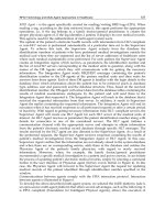
nal tank but on balance with it, as shown in Figure 5-13.
A
week
after the new tank was brought into use, welders were completing
the handrails on the roof when an explosion occurred in the tank.
Two welders were killed, and the tank was blown 20 m into the air,
landing on a nearby building.
L
Figure
5-13.
Extra buffer storage for water was provided by installing a second
tank on balance with the first one. Lack of aeration allowed hydrogen-forming
bacteria to grow, and an explosion occurred.
(Reproduced with permission
of
the American Institute
of
Chemical Engineers. Copyright
0
199.5
AIChE. All
rights reserved.)
124
What Went Wrong?
Investigation showed that the explosion was due to hydrogen
formed by anaerobic bacteria. In the original tank the splashing of
the inlet liquor aerated the water and prevented anaerobic condi-
tions. This did not apply in the new tank
[20].
The incident shows once again how a simple modification, in
this case adding liquid to the bottom
of
a tank instead of the top,
can produce an unforeseen hazard. In the
oil
and chemical indus-
tries we are taught to add liquid to the bottom of a tank, not the
top, to prevent splashing, the production of mist, and the genera-
tion of static electricity (see Section 5.4.1).
No
rule is universal.
Hydrogen produced by corrosion has also turned up in some
unexpected places [see Section
16.2).
As mentioned in Section 1.1.4, bacterial action on river water
can also produce methane.
Fires and explosions that occurred while repairing or demolishing stor-
age tanks containing traces of heavy oil are described in Section 12.4.1 and
an
explosion of a different type is described at the end of Section 1.1.4.
5.4.3
An
Explosion
in an Old Pressure Vessel Used as a Storage Tank
Sometimes old pressure vessels are used as storage tanks. It would
seem that by using a stronger vessel than is necessary we achieve greater
safety. But this may not be the case. as if the vessel fails,
it
will do so
more spectacularly (see Section
2.2
a).
A
tank truck hit a pipeline leading to a group of tanks. The pipeline
went over the top of the dike wall, and
it
broke off inside the dike. The
engine of the truck ignited the spillage, starting a dike fire, which dam-
aged or destroyed 21 tanks and
5
tank trucks.
An
old
lOO-m3 pressure vessel, a vertical cylinder, designed for a
gauge pressure of
5
psi
(0.3
bar). was being used to store. at atmospheric
pressure, a liquid
of
flash point 40°C. The fire heated the vessel to above
40°C and ignited the vapor coming out of the vent: the fire flashed back
into the tank, where an explosion occurred. The vessel burst at the bot-
tom seam, and the entire vessel, except for the base, and contents went
into orbit like a rocket [4].
If the liquid had been stored in an ordinary low-pressure storage tank
with a weak seam roof, then the roof
would have come
off,
and the burn-
ing liquid would have been retained in the rest of the tank.
Storage
Tanks
125
The incident also shows the importance of cooling. with water,
all
tanks or vessels exposed to fire. It
is
particularly important to cool ves-
sels. They fail more catastrophically, either by internal explosion
or
because the rise in temperature weakens the metal (see Section
8.1).
Another tank explosion
is
described in Section
16.2
(a).
5.5
FLOATING-ROOF
TANKS
This section describes some incidents that could only have occurred on
floating-roof tanks.
5.5.1
How
to Sink the
Roof
A
choke occurred in the flexible pipe that drained the roof
of
a float-
ing-roof tank.
It
was decided to drain rainwater off the roof with a hose.
To prime the hose and establish a siphon, the hose was connected
to
the
water supply. It was intended to open the valve on the water supply
f~r
just
long enough to fill the hose. This valve would then be closed and the
drain valve opened (Figure
5-14).
However, the water valve was opened
in
error and left open, with the drain valve shut. Water flowed
onto
the
floating roof and it sank
in
30
minutes (see also Section
18.8).
Temporary modifications should be examined with the same thorough-
ness
as permanent ones (see Section
2.4).
5.5.2
Fires
and
Explosions
(a)
Most
fires
on
floating-roof tanks are small rim fires caused by
vapor leaking through the seals. The source of ignition
is
often
atmospheric electricity.
It
can be eliminated as a source of ignition
-++l
Normal
drain
Figure
5-14.
How
to
sink
the
roof of
a
floating-roof
tank.
126
What Went Wrong?
by fitting shunts-strips of metal-about every meter or
so
around
the rim to ground the roof to the tank walls.
Many rim fires have been extinguished by a worker using a
handheld fire extinguisher. However. in
1979,
a rim fire had just
been extinguished when a pontoon compartment exploded, killing
a fireman. It
is
believed that there was a hole in the pontoon and
some of the liquid in the tank leaked into it.
Workers should not go onto floating-roof tanks
to
extinguish rim
fires
[5].
If fixed fire-fighting equipment is not provided, foam
should be supplied from a monitor.
(b)
The roof of a floating-roof tank had to be replaced. The tank was
emptied, purged with nitrogen. and steamed for six days. Each of
the float chambers was steamed for four hours. Rust and sludge
were removed from the tank. Demolition of the roof was then start-
ed.
Fourteen days later a small fire occurred. About a gallon of
gasoline came out of one of the hollow legs that support the roof
when it is off-float and was ignited by a spark. The fire was put out
with dry powder.
It is believed that the bottom of the hollow leg was blocked with
sludge and that, as cutting took place near the leg, the leg moved
and disturbed the sludge (Figure
5-15).
Before welding or burning is permitted on floating-roof tanks,
the legs should be flushed with water from the top. On some tanks,
the bottoms of the legs are sealed. Holes should be drilled in them
so
they can be flushed through.
(c) Sometimes a floating roof is inside a fixed-roof tank. In many
cases, this will reduce the concentration of vapor in the vapor space
below the explosive limit.
But
in other cases it can increase the
hazard, because vapor that was previously too rich to explode is
brought into the explosive range.
A
serious fire that started in a tank filled with an internal float-
ing roof is described in Reference
[6].
As
a result of a late change in design, the level at which a float-
ing roof came off-float had been raised. but this was not marked on
the drawings that were given to the operators.
As
a result, without
intending to, they took the roof off-float. The pressurehacuum
Storage
Tanks
127
Pontoon Floating rc
Pin
to
locate
leg
L
I
Holes
in leg
so
that height can
P
be
varied
Floor
of
tank
Figure 5-15. Oil
trapped in
the
leg
of
a
floating-roof tank
caught fire
during
demolition.
valve (conservation vent) opened. allowing air to be sucked
into
the space beneath the floating roof.
When the tank was refilled with warm crude oil at
37°C
vapor was
pushed
out
into the space above the floating roof and then out into the
atmosphere through vents on the fixed-roof tank (Figure
5-16).
This
vapor was ignited at a boiler house some distance away.
The fire flashed back
to
the storage tank, and the vapor burned
as it came out
of
the vents. Pumping was therefore stopped.
Vapor
no longer came out of the vents. air got in, and a mild explosion
occurred inside the fixed-roof tank. This forced the floating
TQO~
down like
a
piston. and some
of
the crude oil came up through the
seal past the side of the floating roof and out
of
the vents on the
fixed-roof
tank. This
oil
caught fire. causing
a
number
of
pipeline
joints
to fail, and this caused further
oil
leakages. One small tank
burst; fortunately, it had a weak seam
roof.
More than
50
fire
appliances and
200
firemen attended, and the fire was under con-
trol
in a few hours.
The water level outside the dike rose because the dike drain
valve had been left open. and the dike wall was damaged by the
128
What
Went
Wrong?
Vapor space
Internal floating
roof
Figure
5-16.
Tank
with
internal
floating roof.
fire-fighting operations. The firemen pumped some of the water
into another dike, but
it
ran out because the drain valve on this dike
had also been left open.
An
overhead power cable was damaged by the fire and fell
down, giving someone an electric shock. The refinery staff mem-
bers therefore isolated the power
to
all the cables in the area.
Unfortunately they did not tell the firemen what they were going to
do. Some electrically driven pumps that were pumping away some
of the excess water stopped, and the water level rose even further.
Despite a foam cover, oil floating on top of the water was ignited
by
a
fire engine that was parked in the water. The fire spread rapid-
ly for
150
m. Eight firemen were killed and two seriously injured.
A
naphtha tank ruptured, causing a further spread of the fire, and it
took
15
hours to bring it under control.
The main lessons from this incident are:
1.
Keep plant modifications under control and keep drawings
2.
Do
not take floating-roof tanks off-float except when they
3.
Keep dike drain valves locked shut. Check regularly to
4.
Plan now how to get rid of fire-fighting water. If the drains
5.
During a fire, keep in close touch with the firemen and tell
up
to
date
(see
Chapter
2).
are being emptied for repair.
make sure they are shut.
will not take it, it will have to be pumped away.
them what you propose to do.
Storage
Tanks
429
(d) Roof cracks led
to
an extensive fire on a large (94,000 m3) tank
containing crude oil. The cracking was due to fatigue. the result of
movement of the roof in high winds, and a repair program was
in
hand.
A
few days before the fire, oil was seen seeping from several
cracks, up to
11
in. long, on the single-skin section of the floating
roof, but the tank was kept in use. and no attempt was made
to
remove the oil. The oil was ignited, it
is
believed, by hot particles
of carbon dislodged from a flarestack
108
m away and
76
m
high,
the same height
as
the tank. The fire caused the leaks
to
increase.
and
the
tank was severely damaged. Six firemen were injured when
a release of oil into the dike caused the fire
to
escalate. The fire
lasted
36
hours.
25,000
tons of oil were burned, and neighboring
tanks,
60
m away. were damaged. The insulation
on
one of these
tanks caught fire. and the tank was sucked in, but the precise mech-
anism was not clear [9, 101.
The release
of
oil
into the dike was due to boilover, that
is,
pro-
duction of steam froin the fire-fighting foam by the hot
oil.
As
the
steam leaves the tank, it brings oil with it. Boilover usually occurs
when the heat from the burning
oil
reaches the water layer at the bot-
tom
of the tank, but in this case
it
occurred earlier than usual when
the heat reached pockets of water trapped on the sunken roof
[
14.1,
Most
large floating roofs are made from a single layer
of
steel,
except around the edges, where there are hollow pontoons to give
the roof its buoyancy. The single layer of steel
is
liable to crack,
and any spillage should be covered with foam and then removed as
soon
as possible. Double-deck roofs are obviously safer
but
much
more expensive
[
141.
5.6
MISCELLANEOUS INCIDENTS
5.6.1
A
Tank
Rises
Out
of
the
Ground
A
tank was installed in a concrete-lined pit. The pit was then filled
with sand, and a layer of concrete
6
in. thick was put over the top. Water
accumulated in the pit, and the buoyancy of the tank was sufficient
to
break the holding-down bolts and push it through the concrete covering.
A
sump and pump had been provided for the removal of water. But
either the pump-out line had become blocked
or
pumping had not been
carried out regularly
[7].
130
What Went Wrong?
Underground tanks are not recommended for plant areas. They cannot
be inspected for external corrosion, and the ground is often contaminated
with coirosive chemicals.
5.6.2
Foundation Problems
Part
of the sand foundation beneath
a
12-year-old tank subsided. Water
collected in the space that was left and caused corrosion. This was not
detected because the insulation
on
the tank came right down to the
ground.
When the corrosion had reduced the wall thickness from
6
mm to 2
mm, the floor of the tank collapsed along a length of 2.5 m, and
30,000
m3
of
hot fuel oil came out. Most of
it
was collected in the dike. Howev-
er, some leaked into other dikes through rabbit holes in the earth walls.
All
storage tanks should be scheduled for inspection every few years.
And on insulated tanks the insulation should finish 200 mm above the
base
so
that checks can be made for corrosion.
Tanks containing liquefied gases that are kept liquid by refrigeration
sometimes have electric heaters beneath their bases to prevent freezing of
the ground. When such a heater on
a
liquefied propylene tank failed, the
tank became distorted and leaked-but fortunately, the leak did not ignite.
Failure of
the
heater should activate an alarm.
As
stated in Section 5.2.
frequent complete emptying of
a
tank can weaken the base/wall weld.
5.6.3
Nitrogen Blanketing
Section 5.4.1 discussed the need for nitrogen blanketing. However, if it
is to be effective, it must be designed and operated correctly.
Incorrect design
On one group of tanks the reducing valve on the nitrogen supply was
installed at ground level (Figure
5-17).
Hydrocarbon vapor condensed in
the vertical section of the line and effectively isolated the tank from the
nitrogen blanketing.
The reducing valve should have been installed at roof height. Check
your tanks-there may be more like this one.
Storage
Tanks
131
Hydrocarbon
Valve
Figure 5-17.
Incorrect
installation
of
nitrogen
blanketing.
Incorrect operation
An
explosion and €ire occurred on a fixed-roof tank that was supposed
to
be blanketed with nitrogen. After the explosion,
it
was found that the
nitrogen supply had been isolated. Six months before the explosion the
manager had personally checked that the nitrogen blanketing was
in
operation. But no later check had been carried out
[8].
All
safety equipment and systems should be scheduled
for
regular
inspection and test. Nitrogen blanketing systems should be inspected at
least weekly. It
is
not sufficient to check that the nitrogen is open
to
the
tank. The atmosphere in the tank should be tested with a portable oxygen
analyzer to make sure that the oxygen concentration is below
5%.
Large tanks (say. over
1,000
m;) blanketed with nitrogen should be
fit-
red with low-pressure alarms to give immediate warning of the
loss
of
nitrogen blanketing.
5.6.4
Brittle
Failure
On several occasions a tank has split open rapidly from top to bottom,
as if
it
were fitted with a zipper and someone pulled it. An official report
1151
describes one incident in detail:
The tank. which was nearly
full,
contained
15.000
m3
of
diesel
oil,
which surged out of the failed tank like a tsunami. washing over the dike
walls.
Abo'ut
3.000
m3
escaped from the site into a river that supplied
drinking water for neighboring towns, disrupting supplies for a week.
Fortunately no one was killed.
The collapse was due to a brittle failure that started at
a
flaw in the
shell about
2.4
m
above the base. The fault had been there since the tank
132
What Went Wrong?
was built more than
40
years earlier, and the combination of a full tank
and a low temperature triggered the collapse. For most of the
40
years,
the tank had been used for the storage of a fuel oil that had to be kept
warm; the high temperature prevented a brittle failure. However, two
years before the collapse, the tank had been dismantled, re-erected on a
new site, and used for the storage
of
diesel oil at ambient temperature.
The flaw was close to the edge of a plate, and if the contractor that
moved the tank had cut it up along the welds-the usual practice-some
or all of the flaw might have been removed. However. the tank was cut
up close to the welds but away from them. The flaw was obscured by rust
and residue and could not be seen.
The owner and contractor are strongly criticized in the report for not
complying with the relevant American Petroleum Institute codes. They
did not radiograph all T-joints (the flaw was close to a T-joint and would
have been detected), and they did not realize that the grade of steel used
and the quality of the original welding were not up to modern standards.
The comments about the engineers in charge are similar to those made in
the Flixborough report (see Section
2.4
a): their lack of qualifications
“does not necessarily affect their ability to perform many aspects of a
project engineer’s job. However, when tough technical issues arise, such
as whether
to
accept defective welds, a stronger technical background is
required. If help on such matters was available
.
.
.,
there is no evidence
that
.
.
. utilized
it
.
.
.” (p. 69 of the report).
The summing up of the report reminds us
of
similar comments made
about many serious accidents in other industries: the company (a large
independent
oil
refiner) “failed to take
any
active or effective role in con-
trolling its contractors or establish any procedures which might lead to a
quality job. It was a passive consumer of the worst kind-apathetic as to
potential problems, ignorant
of
actual events, unwilling to take any
engaged role.
Its
employees were
both
institutionally and often personal-
ly unable to respond in any other way. Both the details and the big pic-
ture equally escaped [the company’s] attention. Compared against the
applicable standards, its industry peers, or even common sense [the coni-
pany’s] conduct and procedures can only be considered grossly negli-
gent. The structural collapse
.
.
.
can be directly traced to the supervisory
bankruptcy at [the company]” (p. 79 of the report).
The report also includes a list of other similar tank collapses: six in the
U.S.
in the period 1978-1986 (p. 102).
A
similar incident involving a liq-
uefied propane tank occurred in Qatar in 1977 (see Section 8.1
S).
Storage
Tanks
133
5.7
FRP
TANKS
Tanks made from fiberglass-reinforced plastic are being increasingly
used, but a number
of
failures have occurred. In the United Kingdom 30
catastrophic failures are known to have occurred during the period
1973-1980, and a 1996 report shows that they seem to have been contin-
uing at a similar rate 1211. The following typify the catastrophic failures
that have occurred
[
111:
(a)
A
50
m3 tank made from bolted sections failed because the bolts
holding the steel reinforcements together were overstressed. The
contents-liquid clay-pushed over a wall and ran into the street.
(b) Ninety cubic meters of sulfuric acid was spilled when a tank failed
as the result of stress corrosion cracking.
It
had not been inspected
regularly. and the company was not aware that acid can affect
FRP
tanks. The failure was so sudden that part of the dike wall
was
washed away.
(c)Another tank, used
to
store a hot, acidic liquid, failed because
it
was heated above its design temperature and damaged when dig-
ging out residues. Again, it had not been inspected regularly, and
the company was not aware of the effects of acid.
(d) Forty-five cubic meters of
10%
caustic soda solution was spilled
when the end came off a horizontal cylindrical tank. The
polypropylene lining was leaking, and the caustic soda attacked the
FRP.
(e)Three hundred fifty cubic meters of hot water was spilled and
knocked over a wall when a tank failed at a brewery. The grade of
FRP
used was unsuitable, and the tank had never been inspected
during the three years
it
had been in use. Another failure of a plas-
tic hot water tank is described in Section 12.2.
(f)Thirty tons of acid were spilled when a tank failed.
A
weld was
below standard, and stress corrosion cracking occurred. There had
been no regular inspections.
(g)
An internal lining failed as the result of bending stresses, and the
acidic contents attacked the
FRP.
Cracks in the tank had been
noticed and repaired, but no one investigated why they had
occurred. Finally, the tank failed catastrophically, and the contents
knocked over a wall.
134
What Went Wrong?
@)An FRP tank leaked near a manway after only
18
months in ser-
vice. The wall thickness was too low, the welding was substandard,
and this poor construction was not detected during inspection. The
tank failed the first time it was filled to 85% capacity, and this
sug-
gests that
it
was never tested properly after installation
[2
11.
These incidents show that. to prevent failures of FRP tanks, we should:
1.
Use equipment designed for the conditions
of
use.
2.
Know the limitations of the equipment.
3.
Inspect regularly.
4. Not repair faults and carry on until their cause is known.
These rules, of course, apply generally, but they are particularly
applicable to FRP tanks.
REFERENCES
1.
T.
A. Kletz and
H.
G.
Lawley, in
A.
E. Green (editor).
High Risk
Safe5 Technology,
Wiley, Chichester, UK, 1982, Chapter 2.1.
2.
T. A. Kletz, “Hard Analysis-A Quantitative Approach to Safety,” Sym-
posium Series No.
34,
Institution of Chemical Engineers, 1971, p. 75.
3,
A. Klinkenberg and
J.
L.
van der Minne,
Electrostatics in the Petrole-
iiin
Irzdiutry,
Elsevier, Amsterdam, 1958.
4.
Loss
Prevention,
Vol. 7, 1972, p.
119:
and Manufacturing Chemists
Association,
Case Histov
No.
1887,
Washington, D.C., 1972.
5.
D.
K. McKibben, “Safe Design of Atmospheric Pressure Vessels,”
Paper presented at Seminar on Prevention of Fires and Explosions in
the Hydrocarbon Industries. Institute
of
Gas
Technology, Chicago.
June 21-26, 1982.
6.
Press release issued by the City of Philadelphia Office of the City
Representatives, Dec. 12. 1975.
7.
Petroleum Review,
Oct. 1974. p.
683.
8.
T.
A. Kletz,
Leariziizg
from
Accidents,
2nd edition, Butterworth-
9.
Report
of
the Investigation
into
the Fire ut Anzoco Refinery,
30
Heinemann. Oxford,
UK.
1994, Chapter
6.
August
1983,
Dyfed County Fire Brigade,
UK.
Storage
Tanks
135
10.
Ha,-ardous
Cargo
Bulletin,
Sept. 1983. p.
32;
and Dec. 1983,
p.
32.
1
i.
T.
E. Maddison,
Loss
Prevention Bulletirz,
No.
076. Aug. 1987. p.
3
1.
13.
D. Nevi11 and
G.
C.
White, “Research into the Structural Integrity
of
LNG Tanks,”
New Directions in Process Safeh,
Symposium Series
No.
124, Institution of Chemical Engineers, 1991, p. 425 (discussion).
13.
Loss Preverztion Bulletin,
No. 106. Aug. 1992, p. 5.
1-4.
L.
Streinbrecher.
Loss
Prevention Bullerirz,
No.
088. Aug. 1989.
p.
25.
15.
Report
of
the Investigcition into the Collapse
of
Eink
1338,
Common-
wealth of Pennsylvania Department of Environmental Resources.
Harrisburg, Pa June 1988.
16.
R.
E.
Sanders.
Mmagenzer7t
of
Chaiige in Chemical Plants-Lenix-
ingfrom
Case Histories,
Butterworth-Heinemann. Oxford.
UK,
1993.
17.
F.
E.
Self
and J. D. Hill. ”Safety Considerations When Treating VOC
Streams with Thermal Oxidizers,”
Proceedings
of
the
Tlzirh-firsi
Ariiizial
Loss
Pretyeiztion
Synzposiwrz,
AIChE, New York, 1997.
p.
51.
18.
Loss
Prevention Bulletin,
No.
131, Oct. 1996,
p.
8.
19.
N.
Maddison, “Explosion Hazards in Large Scale Purification
by
Metal Dust,”
Hazards XII-Europearz Acharzces
IIZ
Process Sa-fen.
Symposium Series
No.
134. Institution
of
Chemical Engineers,
Rugby,
UK,
1994.
20.
R.
S.
Rowbottom,
Pulp and Paper Caizada,
Vol. 90.
No.
4.
1989,
p.
“138.
21.
A. Trevitt,
The Chemical Engineer;
No.
27. Oct. 10, 1996. p. 27.
Stacks, like storage tanks, have been the sites of numerous explosions.
They have also been known to choke.
6.1
STACK
EXPLOSIONS
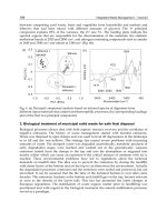
(a) Figure 6-1 shows the results of an explosion in a large flarestack.
The stack was supposed to be purged with inert gas. However, the
flow was not measured and had been cut back almost to zero to
save nitrogen. Air leaked in through the large bolted joint between
unmachined surfaces. The flare had not been lit for some tinie.
Shortly after
it
was relit, the explosion occurred-the next time
some gas was put to stack. The mixture of gas and air moved up
the stack until it was ignited by the pilot flame.
To prevent similar incidents from happening again:
1.
Stacks should be welded. They should not contain bolted joints
between unmachined surfaces.
2.
There
should be a continuous flow
of
gas up every stack to pre-
vent air diffusing down and to sweep away small leaks of air into
the stack. The continuous flow of gas does not have to be nitro-
gen-a waste-gas stream
is
effective. But if gas is not being
flared continuously,
it
is usual to keep nitrogen flowing at a linear
velocity of
0.03-0.06
ds.
The
flow
of gas should be measured. A
higher rate is required if hydrogen or hot condensable gases are
being flared.
If
possible, hydrogen should be discharged through a
separate vent stack and not mixed with other gases in
a
flarestack.
136
Stacks
137
Figure
6-1.
Base
of
flarestack.
3.
The atmosphere inside every stack should be monitored regular-
ly, say daily, for oxygen content. Large stacks should be fitted
with oxygen analyzers that alarm at
5%
(2%
if hydrogen is pre-
sent). Small stacks should be checked with
a
portable analyzer.
These recommendations apply to vent stacks as well as
flarestacks.
138
What Went Wrong?
(b) Despite the publicity given to the incident just described, another
stack explosion occurred nine months later in the same plant.
To prevent leaks of carbon monoxide and hydrogen from the
glands of a number of compressors getting into the atmosphere of
the compressor house, they were sucked away by a fan and dis-
charged through a small vent stack. Air leaked into the duct
because there was a poor seal between the duct and the compressor.
The mixture of air and gas was ignited by lightning.
The explosion would not have occurred if the recommendations
made after the first explosion had been followed-if there had been
a flow of inert gas into the vent collection system and if the atmos-
phere inside had been tested regularly for oxygen.
Why were they not followed? Perhaps because
it
was not obvi-
ous that recommendations made after an explosion on a large
flarestack applied to a small vent stack.
(c)Vent stacks have been ignited by lightning or in other ways on
many occasions. On several occasions, a group of ten or more
stacks have been ignited simultaneously. This
is
not dangerous pro-
vided that:
1.
The gas mixture in the stack is not flammable
so
that the flame
cannot travel down the stack.
2.
The flame does not impinge on overhead equipment. (Remember
that in a wind,
it
may bend at an angle of
45".)
3. The flame can be extinguished by isolating the supply of gas or
by injecting steam or an increased quantity of nitrogen. (The gas
passing up the stack will have to contain more than
90%
nitrogen
to prevent it from forming
a
flammable mixture with air.)
(d)
A
flare stack and the associated blowdown lines were prepared for
maintenance by steaming for
16
hours. The next job was to isolate
the system from the plant
by
turning a figure-8 plate in the 3541-1.
(0.9-m) blowdown line.
As
it was difficult to turn the figure-8 plate
while steam escaped from the joint, the steam purge was replaced
by a nitrogen purge two hours beforehand.
When the plate had been removed for turning, leaving a gap
about
2
in.
(50
min) across, there was an explosion.
A
man was
blown off the platform and killed.
Stacks
139
The steam flow was
0.55
tonkr, but the nitrogen
flow
was only
0.4
ton/hr, the most that could be made available.
As
the system
cooled. air was drawn in. Some liquid hydrocarbon had been left in
a blowdown vessel, and the air and hydrocarbon vapor formed a
flammable mixture. According to the report. this moved up the stack
and was ignited by the pilot burner, which was still lit. It
is
possible.
however, that it was ignited by the maintenance operations.
As
she steam was hot and the nitrogen was cold, much more
nitrogen than steam was needed to prevent air from being drawn
into the stack. After the explosion, calculations showed that
1.6
tons/hu were necessary. four times as much as the amount supplied.
After the explosion, the company decided
to
use only nitrogen in
the future. not steam
[5].
Should the staff have foreseen that steam in the system would
cool and that the nitrogen
flow
would be too small to replace
It?
Probably the method used seemed
so
simple and obvious that
no
one stopped to ask if there were any hazards.
(e) Three explosions occurred in a flarestack fitted, near the tip, with a
water seal. which was intended to act as a flame arrestor and pre-
vent flames from passing down the stack. The problems started
when, as a result
of
incorrect valve settings, hot air was added to the
stack that was burning methane. The methane/air mixture was in the
explosive range, and as the gas was hot
(300°C),
the flashback
speed from the flare
(12
ds)
was above the linear speed
of
the gas
(10
ids
in the tip,
5
ds
in the stack). An explosion occurred, which
probably damaged the water seal, though no one realized this
at
the
time. Steam was automatically injected into the stack, and the flow
of
methane was tripped. This extinguished the flame. When
flow
was restarted, a second explosion occurred, and as the water seal
was damaged, this one traveled right down the stack into the knock-
out drum at the bottom. Flow was again restarted, and this time the
explosion was louder.
The
operating team then decided
to
shut
down the plant
[6].
We should not restart
a
plant after an explosion
(or other hazardous event) until we know why it occurred.
(f)
Another explosion, reported in
1997,
occurred, like that described
in
(a)
above, because the nitrogen flow to a stack was too
low.
It
was cut back by an inexperienced operator; there was no low-flow
alarm or high-oxygen alarm
[7].
The author shows commendable
140
What
Went Wrong?
frankness in describing the incident
so
that others may learn from
it, but nowhere in the report (or editorial comment) is there any
indication that the lessons learned were familiar ones, described in
published reports decades before.
For
other stack explosions see Section
7.13
c and Reference
1.
6.2
BLOCKED
STACKS
(a) Section
2.5
a described how an 8-in diameter vent stack became
blocked by ice because cold vapor (at
-lOO°C) and steam were
passed up the stack together. The cold gas met the condensate run-
ning down the walls and caused
it
to freeze.
A
liquefied gas tank
was overpressured, and a small split resulted. The stack was
designed to operate without steam. But the steam was then intro-
duced to make sure that the cold gas dispersed and did not drift
down to ground level.
(b) The vent stack was replaced by a 14-in diameter flarestack with a
supply of steam to a ring around the top of the stack.
A few years
later this stack choked again, this time due to a deposit of refracto-
ry debris from the tip, cemented together by ice (as some conden-
sate from the steam had found its way down the stack). Fortunate-
ly, in this case the high pressure in the tank was noticed before any
damage occurred. There was no boot at the bottom of the stack to
collect debris (Figure
6-2).
A
boot was fitted
[2].
(c) On other occasions, blowdown lines or stacks have become
blocked in cold weather because benzene or cyclohexane, both
of
which have freezing points of
5°C
were discharged through them.
Steam tracing of the lines or stacks may be necessary.
(d)
Blowdown
lines should never be designed with a dip in them, or
liquid may accumulate in the dip and exert a back pressure. This
has caused vessels to be overpressured
[3].
(e)A blowdown line that was not adequately supported sagged when
exposed to fire and caused a vessel to be overpressured.
(f)
Water seals have frozen in cold weather. They should not be used
except in locales where freezing cannot occur.
Stacks
141
Actual
Better
Figure
6-2.
Flarestack after fall of debris.
Flare and vent systems should be simple. It is better
to
avoid
water seals than install steam heating systems and low-temperature
alarms, which might fail.
(g)
Vent stacks are sometimes fitted with flame arrestors to prevent a
flame on the end of the stack from traveling back down the stack.
The arrestors are liable
to
choke unless regularly cleaned. They are
also unnecessary. because unless the gas mixture in the stack is
flammable, the flame cannot travel down the stack. If the gas mix-
ture in the stack is flammable, then it may be ignited in some other
way. Stacks should therefore be swept by
a
continuous Row
of
gas
to
prevent
a
flammable mixture from forming, as discussed
in
Sec-
tion
6.1.
There are. however, two cases in which flame arrestors
in
vent
stacks are justified:
1.
If the gas being vented can decompose without the addition of
air; an example is ethylene oxide. Whenever possible, such gases
should be diluted with nitrogen.
If
this
is
not always possible, a
flame arrestor may be used.
2.
In the vent pipes of storage tanks containing a flammable
mix-
ture of vapor and air (Section
5.4.1).
Such flame traps should be
inspected regularly and cleaned if necessary. Section
5.3
a
described how a tank was sucked in because the flame arrestors
on
all
three vents had not been cleaned €or two years.
A
type
of
flame arrestor that can be easily removed for inspec-
tion without using
tools
is
described in Reference
4.
(h)
Molecular seals have been choked by carbon from incompletely
burned gas, and water seals could be choked in the same way.
For
142
What Went Wrong?
this reason, many companies prefer not to use them. If they are
partly choked, burning liquid or particles of hot carbon may be
expelled when flaring rates are high [9] (see Section 5.5.2 d).
(i) The relief valve on a liquid hydrogen tank discharged to atmos-
phere through a short stack. The escaping hydrogen caught fire. The
fire service poured water down the stack: the water froze, and the
tank was overpressured and split. The fire should have been extin-
guished by injecting nitrogen up the stack, as discussed in Section
6.1 c.
The common theme of many of these items
is
that blowdown lines and
flare and vent stacks should be kept simple because they are part
of
the
pressure relief system. Avoid flame arrestors, molecular seals, water
seals, and U-bends. Avoid steam, which brings with it rust and scale and
may freeze.
6.3
HEAT RADIATION
The maximum heat radiation that people are exposed to from a
flarestack should
not
exceed 4.7 kW/m2
(1,500
Btu/ft'/hr), about three
times the peak solar radiation in the tropics. Even this amount of radia-
tion can be withstood without injury for only a minute or two. The maxi-
mum to which people may be exposed continuously is about 1.7 kW/m2
(500 Btu/ftVhr).
In
the neighborhood of flarestacks (say, wherever the
radiation could exceed 1.7 kW/m?), the temperatures reached by cables,
roofing materials. and plastic equipment should all be reviewed to make
sure they cannot be damaged [8,9].
REFERENCES
1.
J.
L.
Kilby,
Chemical Engirzeerirzg Progress,
June 1968, p. 419.
2.
T.
A. Kletz.
Chemical Engineering Progress,
Vol. 70,
No.
4,
Apr.
1974, p. 80.
3.
T.
J.
Laney, in
C.
H.
Vervalin (editor),
Fire Protectiori Manual
for
Hydrocarbon Processing Plants,
Vol. 1, 3rd edition, Gulf Publishing
Co.,
Houston, Texas, 1985, p. 101.
Stacks
143
4.
T.
A.
Kletz,
Learning
from
Acciderzts,
2nd edition, Butterworth-
5.
Loss
Prevention Bulletirz,
No.
107, Oct. 1992.
p.
23.
6.
V.
&I.
Desai,
Process Safety Progress,
Vol.
15,
No.
3,
Fall
1996,
7.
T.
Fishwick,
Loss Prevention Bulletin,
No.
135, June 1997.
p.
18.
8.
F.
P.
Lees.
Loss
Prevention in tlie Process Iizdustries,
2nd edition,
9.
D.
Shore,
J~ZWFZC~
of
Loss
Prevention
in
the Process Industries,
Vol.
Heinemann, Oxford,
UK.
1994, Section 7.6.
p.
166.
Butterworth-Heinemann, Oxford,
UK,
1996, Chapter 16.
9.
No.
6,
Nov.
1996.
p.
363.
Chapter
7
leaks
A
small leak will sink
a
great
ship.
-Thomas
Fuller.
1732
Leaks of process materials are the process industries’ biggest hazard.
Most of the materials handled will not burn or explode unless mixed with
air in certain proportions.
To
prevent fires and explosions. we must there-
fore keep the fuel
in
the plant and the air out of the plant. The latter is
relatively easy because most plants operate at pressure. Nitrogen is wide-
ly used to keep air out of low-pressure equipment, such as storage tanks
(Section
5.4),
stacks (Section
6.1).
centrifuges (Section
10.
I),
and equip-
ment that is depressured for maintenance (Section
1.3).
The main problem in preventing fires and explosions is thus prevent-
ing the process material from leaking out of the plant. that
is,
maintaining
plant integrity. Similarly. if toxic or corrosive materials are handled, they
are hazardous only when they leak.
Many leaks have been discussed under other headings, including
leaks
that occurred during maintenance (Chapter
l),
as the result of human
error (Chapter
3),
or
as
the result of overfilling storage tanks (Section
5.1).
Other leaks have occurred as the result of pipe or vessel failures
(Chapter
9),
while leaks of liquefied flammable gas are discussed in
Chapter
8
and leaks from pumps and relief valves in Chapter
10.
Here, we discuss some other sources of leaks and the isolation and
control of the leaking material.
144
Leaks
145
9.1
SOME COMMON SOURCES
OF
LEAKS
7.t.
.I
Small
Cocks
Small cocks have often been knocked open or have vibrated open.
They should never be used as the sole isolation valve (and preferably not
at
all)
on
lines carrying hazardous materials, particularly flammable or
toxic liquids. at pressures above their atmospheric boiling points (for
example, liquefied flammable gases or most heat transfer oils when hot).
These liquids turn to vapor and spray when they leak and can spread long
distances.
It
is
good practice to use other types of valves for the first isolation
valve. as shown in Figure
7-
1.
7.1.2
Drain
Valves
and
Vents
Many leaks have occurred because workers left drain valves open
while draining water from storage tanks or process equipment and then
returned to find that oil was running out instead of water.
In
one incident,
a
man was draining water, through a ?-in diameter
line. from a small distillation column rundown tank containing benzene.
He left the water running for a few minutes to attend to other jobs. Either
there
was
less water than usual
or
he was away longer than expected. He
returned
to
find benzene running out of the drain line. Before he could
close
it.
the benzene was ignited by the furnace which heated the distilla-
tion column. The operator was badly burned and died from his injuries.
The furnace was too near the drain point (it was about
10
m away),
and the slope of the ground allowed the benzene to spread toward the
Primary Isolation Secondary Isolation
nonhazardous
Figure
7-1.
Sinal1
cocks
should
not
be
used
as
primary
isolation
valves.
146
What
Went
Wrong?
furnace. Nevertheless, the fire would not have occurred if the drain valve
had not been left unattended.
Spring-loaded ball valves should be used for drain valves. They have
to be held open, and they close automatically if released. The size
of
drain valves should be kept as small as practicable. With liquefied flam-
mable gases and other flashing liquids,
%
in. should be the maximum
allowed.
Drain valves that are used only occasionally
to empty equipment for
maintenance should be blanked when not in use. Regular surveys should
be made to see that the blanks are in position. On one plant, a survey
after a turnaround showed that
50
blanks were loose, each hanging on
one bolt.
If water has to be drained regularly from liquefied flammable gases or
other flashing liquids, and if a spring-loaded valve cannot be used, then a
remotely operated emergency isolation valve (see Section 7.2.1) should
be installed in the drain line.
When flammable materials are used, drain valves should not be locat-
ed above hot pipework or equipment. A fire
on
an ethylene plant started
when a mixture
of
water and naphtha was drained through a %-in. drain
valve onto pipework at 315°C. It took a long time to replace damaged
control and electric cables [21].
Drain valves should not be located above places where pools of water
are liable to form. as leaks may then spread a long way (see Section
1.4.4).
While drain valves are installed to get rid of unwanted liquid, vent
lines get rid of unwanted gas or vapor. They should be located
so
that the
vapor is unlikely to ignite,
so
that damage is minimal if it does ignite,
and
so that people are not affected by the gas or vapor discharged. One
fire destroyed
a
small plant. It started because the vent on
a
distillation
column condenser discharged into the control room. possibly to prevent
pollution of the surroundings, which had given rise to complaints about
the smell
[
11
(see Section 2.11.3).
An electrician went up a ladder to repair a light fitting and was affect-
ed by fumes corning out of a vent about a meter away. The electrical haz-
ards and the hazards of working from a ladder were considered, but no
one thought about the hazards introduced by the vent-yet vents are
designed
to vent.
Leaks
147
While contractors were working in a building, they inadvertently
burned some insulation material. The ventilation system spread the
fumes around the building. Two people were affected by them. and an
expensive experiment taking place in a laboratory was ruined
[15].
Before authorizing hot work in a building, consider the effects of any
fumes that might be produced and, if necessary. switch of€ or isolate
the
ventilation system.
7.1.3
Open Containers
Buckets and other open-topped containers should never be used for
collecting drips
of
flammable, toxic. or corrosive liquids or for carrying
small quantities about the plant. Drips. reject samples, etc., should be
collected
in
closed metal cans, and the caps should be fitted before the
cans are moved.
One man was badly burned when he was carrying gasoline in a bucket
and
it
caught fire. The source of ignition was never found. Another man
was
carrying phenol in a bucket when he slipped and fell. The phenol
spdbed onto his legs. One-half hour later he was dead.
A
third man was
moving a small open-topped drum containing hot cleaning fluid. He
slipped: liquid splashed onto him and scalded him.
A
workman was draining hot tar from a portable kettle into a bucket
when
it
caught fire.
As
he stepped back his glove stuck to the handle of the
bucket, tipping it up and spilling the burning tar over the ground. The drain
valve
on
the kettle was leaking, and this allowed the fire to spread. Two
small liquefied-petroleum-gas containers (about
100
L).
a trailer, and the
kettle were destroyed. The end of one
of
the tanks was thrown
40
m
[22].
Other incidents are described in Sections 12.2 c and
15.1.
These incidents may seem trivial compared with those described in
other pages. But for the men concerned, they were their Flixborough.
Similarly. glass sample bottles should never be carried by hand. Workers
have been injured when bottles they were carrying knocked against projec-
tions
and broke. Bottles should be carried in baskets or other containers,
such as those used €or soft drinks. Bottles containing particularly haz-
ardous chemicals, such
as
phenol. should be carried in closed containers.
Flammable liquids should. of course, never be used for cleaning floors
or
for cleaning up spillages of dirty oil. Use nonflammable solvents or
water plus detergents.