What Went Wrong Part 7 ppsx
Bạn đang xem bản rút gọn của tài liệu. Xem và tải ngay bản đầy đủ của tài liệu tại đây (1.12 MB, 30 trang )
Leaks
153
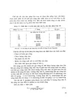
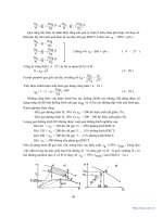
Figure
7-4.
A
soft plastic “top hat” plug (left) was fitted
to
the end of a railway
carriage brake pipe to keep it clean. It was the same color as the end
of the pipe
and was not noticed and removed before the pipe was installed. The brakes
failed, and the train overran.
A
more rigid plug with a larger lip (right) would
have failed the brake test and would have been more visible.
(Photo
courtesy
of
Roger Ford.)
A
more rigid plug with a larger lip, as fitted to the other end
of
each pipe (Figure
7-4
right), would have caused the brake test to
fail. The larger lip, and a different color, would have made the plug
more visible. However, plastic bags tied over the ends would be a
better way of keeping the hoses clean
[25].
Other hose failures are described in Section
13.2.
7.1.7
Cooling Coils
The cooling coil in a storage tank developed a small leak. To prevent
the liquid in the tank from leaking into the cooling water, the coil was
isolated but kept up to pressure by closing and slip-plating the exit water
valve but leaving the inlet valve open. The tank contained an aqueous
solution of a toxic acid,
so
a small leak of water into the tank contents
did not matter and was far preferable to a leak of the acid into the cooling
water. Another coil provided all the cooling necessary.
Ten years later, there was a pressure surge on the cooling water lines
when the cooling water pumps were changed over; this caused a sample
154
What Went Wrong?
valve on the inlet water line to the coil to leak inside the building. The
leaking water was contaminated with acid, which had been lying in the
coil for ten years since the leak first occurred. There were no instructions
for the changeover of the cooling water pumps, and on the occasion of
the incident the valves were operated in an unusual order.
7.2
CONTROL
OF
LEAKS
7.2.1
Emergency
Isolation
Valves (EIVs)
Many fires have been prevented or quickly extinguished by remotely
operated emergency isolation valves. We cannot install them in the lines
leading to all equipment that
might
leak. However, we can install them in
the lines leading to equipment that, experience shows, is particularly liable
to leak (for example, very hot or cold pumps or drain lines, as described in
Section 7.1.2) or in lines from which, if a leak did occur, a very large quan-
tity of material, say 50 tons or more, would be spilled (for example, the
bottoms pumps or reflux pumps on large distillation columns).
In all these cases, once the leak starts. particularly if it ignites, it is
usually impossible to approach the normal hand-isolation valves to close
them. Emergency isolation valves are discussed in detail in Reference
3,
and the following incidents show how useful they can be. They can be
operated electrically, pneumatically, or in some cases, hydraulically.
(a) A leak of light oil from a pump caught
fire.
The flames were
10
m
high. From the control room, the operator closed a remotely operated
valve in the pump suction line. The flames soon died down, and the
fire burned itself out in 20 minutes. It would have been impossible to
have closed a hand-operated valve in the same position. And if the
emergency valve had not been provided, the fire would have burned
for
many hours. The emergency valve had been tested regularly.
It
could not be fully closed during testing but was closed part way.
Backflow from the delivery side of the pump was prevented by a
check (nonreturn) valve. In addition. a control valve and a hand
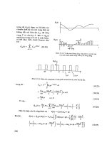
valve well away from the fire were closed (Figure 7-5).
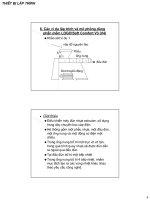
(b) The bearing on the feed pump to a furnace failed, causing a gland
failure and a leak of hot oil. The oil caught fire, but an emergency
isolation valve in the pump suction line was immediately closed,
and the fire soon died out (Figure 7-6).
Leaks
155
Feed Vessel at
Remotely Operated
Isolation Valve
Control Valve
Valve
Spare
Pump
Figure
7-5.
An emergency isolation valve stopped a fire.
Heat exchanger
Figure 7-6.
Another emergency isolation valve stopped a fire.
The control valve in the delivery line to the furnace was also
closed. Unfortunately, this valve was bypassed by the line through
the heat exchanger. In the heat of the moment, no one remembered
to close the valve in the bypass line. In addition, the check (nonre-
turn) valve did not hold. The return flow of oil from the furnace
was stopped by closing a hand valve next to the furnace, which was
about
30
m from the fire. Afterward, another
EIV
was installed in
the pump delivery line.
156
What Went Wrong?
After the fire, the check valves on all three pumps were found to
be out of order, On one the seat had become unscrewed. On anoth-
er the fulcrum pin was badly worn. On the third the pin was worn
right through, and the flap was loose. The valves had not been
inspected since the plant was built.
Check valves have a bad name among many plant operators.
However, this is because many of these valves are never inspected
or tested.
No
equipment, especially that containing moving parts,
can be expected to work correctly forever without inspection and
repair. When check valves are relied on for emergency isolation,
they should be scheduled for regular inspection.
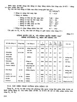
Figure
7-7
shows a fluidic check valve that contains no moving
parts. There is a low resistance to flow out of the tangential open-
ing but high resistance to flow,
200
times higher, in the other direc-
tion. There is thus at times a small flow in the wrong direction, but
if this can be tolerated the valves are very reliable and good at stop-
ping pressure surges that might damage upstream equipment
[26j.
The EIV was not affected by the fire. But it was close to it, and
the incident drew attention to the need to either place EIVs where
they are unlikely to be affected by fire or to provide them with fire
protection. Fire-resistant sacks and boxes are available
[9,
101.
The impulse lines-electrical or pneumatic-leading to EIVs
should also be fire-protected
[
111.
If control valves are used for emergency isolation, a special
switch may be necessary, out on the plant, to close them in an
emergency
so
that operators do not have to go to the control room
to alter the set-points on the controllers.
Forward
Flow
(Low Resistance)
Reverse
Flow
(High
Resistance)
Figure
7-7.
Fluidic
check
valve.
(Illustration courtesy
of
AEA
Technology.)
Leaks
157
Not
e that the operation of an emergency isolation valve should
automatically shut down any pump in the line and trip the fuel sup-
ply to any furnace.
!c) In contrast, on other occasions, EIVs failed to control fires because
the installation was not up to standard. In one case. a fire burned
for
six
hours because the button controlling the EIV was too close
to
the leaking pump for anyone to operate it safely
[4].
It should
have been at least
10
m away. In another case, an EIV failed
to
work because
it
had not been tested regularly. All EIVs should be
tested regularly, say monthly. If they cannot be closed without
upsetting production. they should be closed part way and tested
fully at shutdowns.
(d)
Emergency isolation valves are. of course.
of
no value if they are
not
used when required. Sometimes when there has been
a
leak of
a
hazardous material, the operators have been tempted
to
try
to
iso-
late the leak without shutting down the plant. In doing
so
they have
taken unnecessary risks. For example, there was
a
bad leak of
propylene on a pump inside
a
building. Four workers were badly
injured. Afterward.
a
lot of money was spent on moving the pumps
into the open air. surrounding them with
a
steam curtain
[5]
and fit-
ting remotely operated isolation valves and blowdown valves. If
another leak should occur, then it would be possible
to
stop the
leak by closing the pump suction valve, opening the blowdown
valve, and switching off the pump motor without any need for any-
one to go near the pumps
[16]
(see Section
8.1.3).
Eight years went by before another bad leak occurred. When
it
did occur. the area around the pumps was filled with
a
visible cloud
of propylene vapor
1
in
deep. Instead
of
using the emergency
equipment. which would have stopped the
flow
of propylene and
shut down the plant, two very experienced foremen went into the
compound, shut down the leaking pump, and started the spare up in
its
place. Fortunately the leak did not fire.
Afterward, when one of the foremen was back in his office, he
realized the risk he had been talung. He complained that he should
not be expected to take such risks. He had forgotten, in his eager-
ness
to
maintain production. that emergency equipment had been
provided
to
avoid the need for such risk taking.
158
What Went Wrong?
Other incidents that might have been controlled by EIVs are described
in Sections
1.5.4
(e)
and 16.1
(g).
EIVS should close quickly but not too quickly, or they may produce
hammer pressures in the pipework, especially if the valves are located in
long lines.
An
extra
30
seconds closing time is unlikely to be serious.
Similarly, EIVs should not open too quickly. If there is a control valve in
the pipework, it should also be closed to back up the EIV; afterward, it
should be opened last, as it will open slowly
[
171.
The actuators fitted to EIVs should be somewhat more powerful than
those recommended by manufacturers, especially if the liquid in the line
is viscous. Some manufacturers do not allow for valve-packing friction
forces
[18].
EIVs, like all safety equipment, should be tested regularly
(see Section
14.2.2).
7.2.2
Other Methods
of
Controlling
Leaks
The following methods have been used successfully:
(a) Injecting water
so
that it leaks out instead of oil. This method can,
of course. be used only when the water pressure is higher than the
oil pressure.
(b) Reducing the plant pressure, thus reducing the size of the leak.
(c) Closing an isolation valve some distance away.
(d) Freezing a pipeline. This method requires time to organize the nec-
essary equipment and can only be used with materials of relatively
high freezing points, such as water or benzene.
(e) Injecting a sealing fluid into a leaking flange or valve gland using a
proprietary process such as Furmaniting. Caution: accidents have
occurred because correct procedures were not followed. Take care
that bolts are not overstressed
[12].
(f)
Confining the spread of the leak by water spray [6,
81
or steam cur-
tains
[5].
The latter have to be permanently installed, but the former
can be temporary or permanent.
(g) Controlling the evaporation from liquid pools by covering with
foam. This method can be used for chlorine and ammonia spillages
as well as hydrocarbon spillages if suitable foams are used.
(h)Adding a less volatile liquid to
a
spillage to reduce its volatility.
When some liquefied petroleum gas
(LPG)
got into the drains,
Leaks
159
some gas oil was poured down them to absorb the LPG and reduce
the chance of an explosion.
7.2.3
How
Not to Control
a
Leak
On many occasions employees have entered a cloud
of
flammable gas
or
vapor to isolate
a
leak. In the incident described in Section
7.2.1
(dj,
this was done to avoid shutting down the plant. More often, it has been
done because there was
no
other way of stopping the leak. The persons
concerned would have been badly burned if the leak had ignited while
they were inside the cloud.
It
would be going
too
far to say that
no
one should ever enter a cloud
of flammable vapor to isolate a leak. There have been occasions when.
by taking
a
risk
for a minute, a man has isolated a leak that would other-
wise have spread a long way and probably ignited. perhaps exploded.
However, we should try to avoid putting people in such situations by pro-
viding remotely operated emergency isolation valves to isolate likely
sources
of
leak.
It may
be
possible to isolate a leak by hand by forcing back the vapor
with water spray and protecting the man who closes the ~al~e in the
same way. The National Fire Protection Association can provide a set
of
slides or a film showing how this is done.
It
is possible to measure the extent
of
a leak
of
flammable gas or vapor
with
a combustible gas detector.
If
the leak is small, a person may be
allowed (but not expected) to
put
his hands. suitably protected, inside the
flammable cloud. But only in the most exceptional circumstances should
a person be allowed to put more
of
his body into the cloud.
7.3
LEAKS ONTO WATER, WET GROUND, OR INSULATION
7.3.1
Leaks
Onto Water or Wet Ground
Section
1.4.4
describes two leaks onto pools
of
water that spread much
farther
than
anyone expected. One was ignited by a welder
20
m
away.
and the other spillage. onto a canal, caught fire
1
km
away.
Hn
other #cases, spillages of oil have soaked into the ground and have
then come to the surface after heavy rain.
A
spillage of gasoline in Essex,
England,
in
1966,
came back
to
the surface two years later. The vapor
accumulated
on
the ground floor of a house, ignited, and blew
a
hole in
160
What Went Wrong?
the stairs, injuring two people.
A
trench
7
m deep was dug to recover the
rest of the gasoline
[7].
In other cases, spillages of oil have leaked into sewers and from there
into houses.
If a substantial quantity of oil is spilled into the ground, attempts
should be made to recover it by digging a well or trench.
7.3.2
Leaks
Onto
Insulation
When organic compounds come into contact with many hot insulation
materials, they can degrade, and the auto-ignition temperature can fall by
100"-200°C.
Many fires have started in this way (see Section
12.4.4).
Most of them have been small, but some have been serious. For example,
on a plant in Belgium in
1989,
ethylene oxide (EO) leaked through a
hairline crack in a weld on a distillation column and contaminated the
rock wool insulation
on
a level indicator. The
EO
then reacted with mois-
ture to form nonvolatile polyethylene glycols. The metal covering of the
insulation was removed
so the level indicator could be repaired. Air
leaked in, and later the same day the polyethylene glycols ignited. This
heated the wall of the piping system, in which there was no flow. The
heat caused the
EO
to decompose explosively-a well-known reaction-
and the decomposition traveled into the distillation column. which
exploded. Figure
7-8
shows the result.
The source of ignition of the polyethylene glycol was probably auto-
ignition of the degraded material. The report recommends the use of non-
absorbent insulation for equipment containing heat-sensitive materials
such
as EO
[19,
201.
In another incident, a long-chain alcohol leaked into the insulation of a
pipeline. When the covering over the insulation was opened, allowing air
to enter, the temperature
(60°C)
was sufficient for ignition
[
191.
7.4
DETECTION
OF
LEAKS
On
many occasions combustible gas detectors have detected a leak
soon after it started, and action to control
it has been taken promptly.
Installation of these detectors is strongly recommended whenever lique-
fied flammable gases or other flashing liquids are handled or when expe-
rience shows there is a significant chance of a leak [3]. Detectors are also
162
What Went Wrong?
available for common toxic gases. However, these detectors do not do
away with the need for regular patrols of the plant by operators. Several
plants that have invested heavily in gas detectors report that, neverthe-
less. half the leaks that have occurred have been detected by people.
On
one plant, liquid leaks drained into a sump that was fitted with a
level detector. When a leak actually occurred, it dripped onto a hot pipe
and evaporated and was not detected for many hours (see Section
20.2.4).
A similar incident occurred on another plant. The liquid in the plant was
cold,
so
a low-temperature alarm was installed in the sump. It was tested
with cold water and worked well. When a leak occurred, the leaking liquid,
which was acidic, reacted with the steelwork on its way to the sump and
warmed up; the temperature element could not, of course, tell the differ-
ence between warm air and warm liquid and failed to detect the leak.
Whenever possible we should measure directly what we need to know
and not some other property from which it can be deduced (see Section
14.6).
Electric cables that detect liquid leaks are available. They can be run
through areas where leaks are possible, and they indicate the presence
and location of a leak.
Large leaks can be detected by comparing flow rates in different parts
of a plant. This can be done automatically on plants that are computer-
controlled.
7.5
FUGITIVE
EMISSIONS
There is increasing interest in fugitive emissions, small continuous
leaks from flanges, valve and pump glands, relief valves, etc., which pro-
duce small but ever-present concentrations of chemicals
in
the workplace
environment and some of which may produce long-term toxic effects.
Reference
13
summarizes published data on the leak rates from various
items
of
equipment and ways of reducing them. According to Reference
14,
more than half the total emission from a refinery comes from valve
glands. Actual figures are:
Leaks
163
Source Percent
of
Total
Emission
Flanges
Valves
Compressors
Pumps
Relief valves
Separators
Cooling towers
Drains
8
57
3
12
1
4
7
8
REFERENCES
1. Health and Safety Executive,
The Explosion and Fire
at
Chenzstnr
Ltd.!
6
September
1981,
Her Majesty’s Stationery Office, London,
1982.
2.
C.
T.
Adcock and J.
D.
Weldon,
Chemical Engineering Progress,
Vol.
63,
No.
8,
Aug. 1967, p. 54.
3.
T.
A.
Kletz,
Clzemical Engineering Progress,
Vol.
71,
No.
9, Sept.
1975, p. 63.
4.
T.
A.
Metz.
Hydrocarbon Processing,
Vol.
58,
No.
1,
Jan.
1979.
p.
243.
5.
H.
G.
Simpson,
Pori-er
and Works Engineering,
May
8.
1974,
p.
8.
6. J. McQuaid and
R.
D.
Fitzpatrick,
J.
of
Hazardous Materials,
Vol.
5,
1983,
p.
121; and
J.
McQuaid,
J.
of
Hazardous Materials,
Vol.
5,
1983, p. 135.
7.
Petroleum Times,
Apr.
11, 1969.
8.
K.
Moodie.
Plant/Operations Progress,
Vol.
4,
No.
4.
Oct. 1985,
p.
234.
9.
M.
Symalla,
Hydrocarbon Processing,
Vol. 63.
No.
7, July 1984,
p.
83.
10. A.
E.
Choquette,
Hydrocarbon Processing,
Vol. 63,
No.
7, July 1984,
11.
G.
K.
Castle.
Hydrocarbon Processing,
Vol.
63,
No.
3,
Mar.
1984,
12.
H.
J. Maushagen,
Loss Prevention Bulletirz,
No.
055, Feb. 1984, p.
1.
p. 85.
p.
113.
164
What Went Wrong?
13. British Occupational Hygiene Society,
Fugitive Emissions
of
Vapo~~rs
froin
Process Equipment,
Report in
Science Reviews,
Northwood,
UK, 1984.
14. C. R. Freeberg and C. W. Ami,
Chemical Engineering Progress,
Vol.
78,
No.
6, June 1982, p. 35.
15.
Coordinating
Corzstruction/Mairzterzance
Plans nyith FaciliQ Manag-
er May Deter Uizexpected Problems and Accidents,
Safety Note
DOEEH-0127,
U.S.
Dept. of Energy, Washington, D.C., Apr. 1990.
16.
T.
A. Kletz,
Lessons
From
Disaster:
How
Organizations Have
No
Menzory and Accidents Recur;
co-published by Institution of Chemi-
cal Engineers, Rugby, UK. and Gulf Publishing
Co.,
Houston, Texas,
1993, Sections 2.2 and
8.10.
17. B. T. Matusz and D.
L.
Sadler, “A Comprehensive Program for Pre-
venting Cyclohexane Oxidation Process Piping Failures,” Paper pre-
sented at AIChE
Loss
Prevention Symposium. Houston, Texas,
Mar./Apr. 1993.
18.
Undersized Wve Actuators,
Safety Note DOEEH-0113,
U.S.
Dept.
of Energy, Washington. D.C Oct. 1989.
19. Loss
Prevention Bulletin,
No.
100, Aug. 1991, p.
1.
20.
L.
Britton,
Plant/Operatiorzs Progress,
Vol. 9,
No.
2, Apr. 1990, p.
21.
Loss
Prevention Bulletin,
No. 131, Oct. 1996, p. 13.
22.
Occupational Health and Safety Obsewer;
Vol.
3,
No.
12, U.S. Dept.
23.
Loss Prelyentiorz Bulletin,
No. 134, Apr. 1997, pp.
3.
5,
and 6.
24.
Operating Experience Weekly
Sunzmary,
No. 96-45, Office of
Nuclear and Facility Safety,
U.S.
Dept. of Energy, Washington, D.C.,
1996.
p.
10.
75; and Vol.
10,
No.
1,
Jan. 1991. p. 27.
of
Energy. Washington, D.C., Dec. 1994, p. 4.
25.
R.
Ford,
Modern Railuwys,
Vol. 53,
No.
579, Dec. 1996, p. 752.
26. Literature available
from
AEA Technology, Huntersville, N.C., and
Wairington, UK.
This chapter describes a number of incidents involving liquefied flam-
mable gases (LFG) that could have occurred only with these materials
(or other flashing flammable liquids).
The property
of
LFG that makes
it
so
hazardous is that
it
is usually
stored and handled under pressure at temperatures above normal boiling
points. Any leak thus flashes, much
of
it
turning to vapor and spray. This
can spread for hundreds
of
meters before
it
reaches a source
of
ignition.
The amount
of
vapor and spray produced can far exceed the theoreti-
cal amount of vapor produced, estimated by heat balance
[l].
The vapor
carries some of the liquid with
it
as spray. It may evaporate on contact
with the air.
In
any case, it
is
just as likely to burn or explode.
Any flammable liquid under pressure above its normal boiling point
will
behave like LFG. Liquefied flammable gases are merely the most
common example
of
a flashing liquid. Most unconfined vapor cloud
explosions, including the one at Flixborough (Section
2.4),
have been
due to leaks
of
such flashing liquids
[2].
The term
liquefied
yerl-oZeurn
gas
(LPG)
is
often used to describe those
liquefied flammable gases that are derived from petroleum. The term
LFC
is
preferred when the discussion applies
to
all liquefied flammable
gases. It includes materials such as ethylene oxide, vinyl chloride, and
methylamines. which behave similarly
so
far as their flashing and flam-
mable properties are concerned.
LFGs stored at atmospheric pressure and
low
temperature behave
rather differently from those stored under pressure at atmospheric tem-
165
166
What
Went Wrong?
perature. Incidents involving these materials are described in Sections
2.5, 5.2.2 d,
5.6.2,
and
8.1.5.
8.1
MAJOR
LEAKS
8.1
.I.
Feyzin
The bursting of a large pressure vessel at Feyzin, France. in 1966 was
at the time one of the worst incidents involving LFG that had ever
occurred but has since been overshadowed by the events at Mexico City
(see Section
8.1.4).
It
caused many companies to revise their standards
for the storage and handling of these materials. Because no detailed
account has been published, it is described here. The information is based
on
References
3
through
6
and on a discussion with someone who visited
the site soon after the fire.
An operator had to drain water from a l,20O-m3 spherical storage ves-
sel nearly full of propane (Figure
8-1).
He opened valves A and
B.
When
traces of oil showed that the draining was nearly complete, he shut A and
then cracked it to complete the draining.
No
flow came.
He
opened A
fully. The choke-presumably hydrate, a compound of water and a light
hydrocarbon with a melting point above 0°C-cleared suddenly, and the
operator and two other men were splashed with liquid. The handle came
off valve A, and they could not get it back
on.
Valve
B
was frozen and
could not be moved. Access was poor because the drain valves were
immediately below the tank, which was only
1.4
m
above the ground.
B
Drain Valve
C
Sample Valve
Figure
8-1.
Drain valves underneath propane tank
at
Feyzin.
Liquefied Flammable Gases
167
A
visible cloud of vapor,
1
m deep, spread for
150
m
and was ignited
by a car that had stopped on a nearby road
25
minutes after the leak start-
ed. The road had been closed by the police, but the driver approached
from a side road. The fire flashed back to the sphere, which was sur-
rounded by flames. There was no explosion. The sphere was fitted with
water sprays. But the system
was designed to deliver only half the quan-
tity of water normally recommended
(0.2
U.S.
gal/ftz min. or 8 L/ml
min.), and the supply was inadequate. When the fire brigadc started to
use its hoses, the supply to the spheres ran
dry.
The firemen seemed
to
have used most of the available water for cooling neighboring spheres to
stop the fire from spreading, in the belief that the relief valve would pro-
tect the vessel on fire.
The ground under the sphere was level
so
that any propane that did not
evaporate or bum immediately collected under the sphere and burned later.
Ninety minutes after the fire started, the sphere burst. Ten
out
of
12
firemen within
50
m were killed. Men
140
m
away were badly burned by
a wave of propane that came over the compound wall. Altogether.
15-18
men were lulled (reports differ), and about
80
were injured. The area was
abandoned. Flying debris broke the legs of an adjacent sphere, which fell
over.
Its
relief valve discharged liquid, which added to the €ire, and
45
minutes later this sphere burst. Altogether, five spheres and two other
pressure vessels burst, and three were damaged. The fire spread to gaso-
line and fuel
oil
tanks.
At
first
it
was thought that the spheres burst because their relief valves
were
too
small. But later it was realized that the metal in the upper por-
tions of the spheres was softened by the heat and lost
its strength. Below
the liquid level, the boiling liquid kept the metal cool. Incidents such as
this
one in which a vessel bursts because the metal gets
too
hot are
known
as Boiling Liquid Expanding Vapor Explosions or BLEVEs.
To
prevent such incidents from occurring, many companies-after
Feyzin-adopted recommendations similar to the following:
Recommendations
to
prevent
a
fire from starting
[7]
Restrict the size of the second drain valve
to
%
in., and
plat?
it at least
1
m from the first valve. The drain line should be robust
and
firmly sup-
ported.
Its
end should be located outside the shadow of the tank.
e
Fit
a remotely controlled emergency isolation valve (see Section
7.2.1)
in the drain line.
168
What Went Wrong?
New installations should be provided with only one connection
below the liquid level, fully welded
up
to a first remotely operated
fire-safe isolation valve located clear of the tank area.
9
Install combustible gas detectors to provide early warning of a leak.
Recommendations to prevent a fire from escalating
[7,8]
Insulate vessels with a fire-resistant insulation, such as vermiculite
concrete. This is available as an immediate barrier to heat input.
Unlike water spray,
it
does not have to be commissioned.
In some countries, mounding is used instead of conventional insu-
lation. The tank is completely covered with clean sand or other clean
material. Portions of the covering must be removed from
time
to time
so
that the outside of the tank can be inspected.
*Provide water spray or deluge (unless the vessel is mounded). If
insulation is provided. then water deluge at a rate of
0.06
U.S.
gal/ft2
min.
(2.4
L/m? min.) is sufficient.
If
insulation is not provided, then
water spray at a rate of
0.2
U.S.
gal/ft2 min. (8 L/mZ min.) is neces-
sary. (Deluge water is poured on the top of a vessel; spray is directed
at the entire surface.)
Slope the ground
so that any spillage runs off to a collection pit.
Fit an emergency depressuring valve
so
that the pressure in the vessel
can be reduced to one fifth
of
design in ten minutes to reduce the strain
on
the metal
[13].
The time can be increased to 30 minutes if the vessel
is insulated and to one hour if, in addition, the ground is sloped.
Figure
8-2
summarizes these proposals.
8.1.2
Duque
De
Caxias
A similar incident
to
that at Feyzin occurred at this refinery in Brazil
in
1972. According to press reports, the relief valve failed to open when
the pressure in an LPG sphere rose. To try to reduce the pressure. the
operators opened the drain valve. Little water came out, and the LPG that
followed it caused the valve to freeze, and the flow could not be stopped.
There was only one drain valve. The LPG ignited, the vessel BLEVEd,
and
37
people were killed.
Liquefied Flammable Gases
169
Figure 8-2.
Methods
of
protecting
a
pressure vessel against fire.
If the operators did, in fact, try to reduce the pressure by draining
water. they did not realize that the vapor pressure above a liquid
is
the
same whatever the quantity present.
8.1.3
United
Kingdom
This fire occurred some years ago because those concerned did
not
fully appreciate the difference in behavior between liquid hydrocarbons,
such as naphtha or gasoline, and
LFGs.
The vapor from a spillage of
gasoline will spread only a short distance-about the diameter
of
the
pool.
But the vapor from a spillage of
LFG
can spread for hundreds of
meters.
Some equipment that had been designed and used
for
handling
gaso-
line and similar liquids was adapted to handle propylene.
A
leak occurred
from the gland of a high-pressure reciprocating pump operating at a
gauge pressure of
3,625
psi
(250
bar) due to the failure of the studs hold-
ing the gland in position. The pump was located in an unventilated build-
ing. But the vapor escaped through a large doorway opposite the pump
and was ignited by a furnace
75
m away. Four men were badly burned.
170
What Went Wrong?
The vapor from a spillage of gasoline in the same position would not
have spread anywhere near the furnace.
After the fire, the pump (and others) was relocated in the open air,
under a canopy,
so
that small leaks would be dispersed by natural ventila-
tion. It was surrounded by a steam curtain to disperse larger leaks. This
would not have been necessary
if
the pump could have been located
more than 150 m from sources of ignition. Gas detectors were installed
to give early warning of any leaks. Emergency isolation valves (Section
7.2.1) were provided
so
that the pumps could be isolated safely froin a
distance [9]. What happened when another leak occurred
is
described in
Section 7.2.1 (d).
Note that a common factor in incidents 8.1.1 through 8.1.3 was a fail-
ure by those concerned to understand the properties of the materials and
equipment.
8.1.4
Mexico
City
The fire and explosion at a processing plant and distribution center for
liquefied petroleum gas (LPG-actually 80% butane, 20% propane) in
San Juanico, a suburb of Mexico City, in November 1984, was one
of
the
worst incidents that has ever occurred in the oil and chemical industries,
exceeded only by Bhopal. According to official figures, 542 people were
killed, 4,248 injured, and about
10,000
made homeless; but unofficial
estimates are higher. The disaster started when an 8-in. LPG pipeline rup-
tured. The reason for the failure is not known, but according to one report
[14] a tank was overfilled and the inlet line overpressured. It is not clear
why the relief valve did not lift. The gas cloud covered an area of
200
m
by 150 m before it was ignited, probably by
a
ground-level flare, about
5-10 minutes after the leak started. The gas cloud burned and disap-
peared, but a flame was left burning near the broken pipe, and this flame
heated an LPG sphere, which BLEVEd, causing further damage and fur-
ther BLEVEs. Altogether, four spheres and 15 cylindrical tanks BLEVEd
during the next 1% hours, and some of the tailks landed up to 1,200 m
from the plant
[
151.
Most of those killed and injured were members
of
the public who were
living in a shanty town near the plant. When the plant was built, the nearest
houses were 360 m away, but homes had been allowed to encroach on the
intervening ground until the nearest houses were only 130 m from the plant.
Liquefied
Flammable
Gases
i
71
Although much of the plant was only
a
few years old (some parts were
20
years old), most
of
the recommendations made in Section
8.1.1
and
taken from a report published in 1970
[7]
do not seem to have been fol-
lowed in the design. For example, there were no gas detectors. the water
deluge system was inadequate (or failed to operate), there was little or no
fire insulation (even the legs of the spheres were not insulated), bunds
around the vessels allowed LPG to accumulate where it could do most
harm, and there were many connections to vessels below the liquid level
[
161.
In addition. the plant seems to have been congested and was mush
too
near concentrations of people. A typical recommended distance for
a
large LPG processing area is
600
m
[17],
not 360 m. the original
dis-
tance, or 130
m,
the distance at the time. At Bhopal also (see Section
2
1.9).
uncontrolled spread of
a
shanty town was responsible hr the large
number of casualties.
8.1.5
Qatar
The incidents described
so
far involved LFG stored under pressure at
atmospheric temperature. LFG can also be stored at a low temperature
and
atmospheric pressure. and this method
is
often preferred for large
storages because. due to the low pressure, the leak rate through a hole
of
a given size is smaller, and due to the low temperature. the evaporation
rate is smaller. However, when deciding on the method of storage to be
used, the probability of a leak from the installation
as
a whole. including
the refrigeration and vaporization plants, should be considered. There
will be no gain if we reduce the chance of a leak from the storage tanks
but introduce extra equipment that
is
more likely to leak.
In 1977. the technical press reported that a major leak from a 20,000-
m; liquefied propane tank in Qatar had ignited and that the resulting fire
and explosion had killed seven people and caused extensive damage to
the rest of the plant
[
181.
There had also been a leak the year before, but
it
had not ignited, and the tank had been repaired. The propane was
stored at
-32°C
and atmospheric pressure.
No
detailed report on the inci-
dent was issued, for legal reasons, but a member
of
the company con-
cerned published several papers
[
19-2
11,
which gave new recommenda-
tions for the construction
of
tanks for refrigerated
LFG,
and
it
is thus
possible
EO
read between the lines and surmise what probably happened.
The new recommendations said that refrigerated LFG tanks
should
be
made from materials such
as
9%
nickel steel, which will not propagate
a
172
What
Went
Wrong?
crack if one should start. Previously, the policy of many companies was
to prevent cracks rather than rely on the crack-arresting properties of the
tank material. It thus seems that at Qatar a crack started, despite
the
pre-
cautions taken to prevent such an occurrence, and then propagated rapid-
ly. The reason for the initial crack is not known. It may have been con-
nected with the repairs that were carried out following the crack the
previous year. According to one report
[22],
this crack was due to weld
attack by bacteria in the seawater used for pressure testing. However, the
cause of the crack is of secondary importance compared with the fact that
once it appeared it spread rapidly.
It is now widely recognized that we cannot prevent fires and explo-
sions by eliminating sources of ignition. We do what we can, but they are
still liable to turn up.
So
we try to prevent the formation of explosive
mixtures. Similarly, it is now argued that we cannot eliminate all causes
of cracks, and
so
we should make sure that any that do occur do not
propagate.
At Qatar, the liquid came out with such force that it spilled over the
dike wall. Conventional dike walls also have the disadvantage that
a
large area of liquid is exposed to the atmosphere
if
a leak occurs. For
these reasons it
is
now usual to surround cryogenic storage
tanks
with a
concrete wall, about
1
m from the tank and the full height of the tank. If
the tank is not made from crack-resistant material, then the concrete wall
should be designed to withstand the effects of a sudden release of liquid.
8.1.6
Ethyl
Chloride
Plant
In
1994
a leak of impure ethyl chloride (boiling point
12°C)
caught
fire,
1
?4
hours after it started, and damaged the plant
so
extensively that it
had to be rebuilt. Fortunately, no one was killed or injured. The leak
started at
a
flange assembly on
the
delivery of a pump (Figure
8-3),
prob-
ably due to corrosion of the flanges but possibly due to failure
of
a
plas-
tic bellows. The official report
[23]
made the following points:
The split flanges were badly corroded; their thickness was reduced,
and the bolt holes were much enlarged. (Split flanges are not
a
good
feature because they expose twice
as
much surface to the effects of
corrosion.) There was no system for identifying critical items, the
failure
of
which could have serious results, and registering them for
regular inspection. Maintenance was on a breakdown basis, and there
Liquefied Flammable Gases
173
(Photo courtesy
of
the
UK
Health
and
Safety Executive.)
Figure
8-3.
Split flange assembly similar
to
one that leaked.
were no formal records that could be used to identify items needing
regular inspection or replacement.
The leak could have been stopped as soon as it was detected if an
emergency isolation valve (Section
7.2.1)
had been fitted in the pump
suction line. On the rebuilt plant such valves were fitted on the pump
suction lines, more combustible gas detectors and more extensive
insulation were installed, plastic pump bodies were replaced by metal
ones, and spillages were directed to collection pits. The plant was
built in
1972,
when these features were not common practice; many
improvements had been made since then, but they did not go far
enough. Most of those made after the fire could have been made
beforehand.
The source of ignition may have been a box containing electrical
equipment. It had a badly fitted or incorrect type of plug, which
could have allowed water to enter and to cause arcing.
174
What Went Wrong?
The fire was more serious than it would normally have been because
the inventory in the plant, about
70
tons, was about twice the usual
amount. Some of the overheads from a reactor were collected in a
slops drum and recycled. The inventory in the drum was usually
small. At about
9
a.m. on the day of the fire. the recycle pump failed.
As a result, the level in the drum rose, and the level in the reactor
fell. The operator noticed the fall in the reactor level (but not the
rise
in the drum level) and recycled product to maintain the level. At 8
p.m. the supervisor noticed that the high-level alarm on the slops
drum was lit; he found that the recycle pump had failed, and he
changed over to the spare:
it
leaked
25
minutes later. Section
3.3.1
describes another occasion when operators failed to notice unusual
readings for
11
hours.
The major hazard on the site as a whole was the storage and use
of
chlorine.
So
much attention was devoted
to
this that other hazards
received less attention than they should have.
The official report sums up the lessons of the fire by saying that it
might have been prevented or its severity greatly reduced
if
a more
detailed assessment of the inherent hazards and risks of the plant had
been carried out by the company beforehand and if adequate records
had been kept to build up a history on which an inspection and
replacement program could have been based.
8.2
MINOR
LEAKS
(a) After Feyzin (see Section 8.1.1) one company spent a lot of money
improving the standard of its
LFG
storage facilities-in particular,
the water-draining arrangements-so as to comply with the recom-
mendations made in Section 8.1.1.
Less than a year later, a small leak from a passing drain valve on
a pipeline caught fire. It was soon extinguished by closing the
valve. But
an
investigation disclosed that:
1.
There should have been two valves in series or a single valve
2.
The valve was made of brass and was of a type stocked for use
on domestic water systems. It was not the correct pressure rating
for
LFG.
and blank.
Liquefied Flammable Gases
175
3.
The
valve was screwed onto the pipeline, though the company’s
codes made it clear that only flanged or welded joints were
allowed.
4.
It
was never discovered who installed this unauthorized substan-
dard drain point. An attempt had been made
to
publicize the
lessons of Feyzin, the company’s standards, and the reasons for
them. However, this did not prevent the installation
of
the drain
point. Note that a number of people must have been involved.
Besides the man who actually fitted it and his foreman. someone
must have issued a work permit and accepted
it
back (when he
should have inspected the
job),
and several persons must have
used the drain point. Many must have passed by. If only one
of
them had recognized the subsiandard construction and drawn
ir
to
the attention
of
those responsible, the fire would
not
have
occurred
[
101.
Like the plants in our gardens. our plants grow unwanted
branches while our backs are turned.
(b)A propane sphere was filled with water
to
inert it during repair
work. When the repairs were complete, the water was drained from
the sphere, and propane vapor was admitted
to
the top to replace
the water. The instruction stated that draining should stop when
5
rn3
of
water was left in the vessel. But no one was present when
this stage was reached. All the water drained out. followed by
propane. Fortunately it did not ignite. The job had been
left
because the operators did not realize that the level indicator, which
measured weight, would indicate a level of water almost twice the
actual level. Other similar incidents are described in Section
5.1.2.
If
nitrogen is available, it should be used instead of water for inert-
ing vessels. Or if water
is
used.
it
should be replaced by nitrogen
when it
is
drained. Before filling any equipment with water, always
check that it is strong enough to take the weight of the water
[
1
I].
8.3
OTHER
LEAKS
Numerous leaks of LFG. mainly minor but occasionally more serious,
have occurred from the following items
of
equipment:
176
What Went Wrong?
Flanged joints
The size and frequency of leaks can be reduced by using spiral-wound
gaskets in place of compressed asbestos fiber ones. Screwed joints
should not be used.
Pump seals
The leak size can be reduced by using double mechanical seals or
a
mechanical seal and a throttle bush. the space between the two being
vented to a safe place. Major leaks may still occur. however, due
to
col-
lapse of the bearing or seal.
LFG
pumps should therefore be fitted with
emergency isolation valves (see Section
7.2.1).
particularly if the temper-
ature is low or the inventory that can leak out is high.
Level glasses
These should not be used with flashing flammable liquids (see Section
7.1.4).
Sample points
These should not exceed %-in. diameter.
Small branches
These should be physically robust and well supported
so
they cannot
be knocked off accidentally or vibrate until they fail by fatigue.
Equipment made from grades
of
steel unsuitable for use at
low
temperatures
Materials
of
construction should be chosen
so
the equipment will with-
stand the lowest temperature that can be reached during abnormal opera-
tion. In the past, materials have been used that will withstand normal
operating temperatures but that may become brittle at lower temperatures
reached during plant upsets or abnormal operation, for example, when
the pressure in a vessel containing liquefied petroleum gas is reduced and
the vessel is cooled by evaporation of the liquid (see Section
10.5.2).
Some spectacular failures have resulted
[12]
(see Section
9.2.1
g).
Liquefied Flammable Gases
7
77
Wholesale replacement of such materials in existing plants is impracti-
cal, and there is no universal solution. Some lines can be replaced in dif-
ferent grades of steel. Sometimes low temperature trips or alarms can be
used. Sometimes the need to watch the temperature closely during start-
up
has to be impressed on operators.
Other leaks
of
LFG are described in Sections 1.1.6 (e), 1.5.4
(a).
5.2.2
(d),
9.1.6
(d)
and (f). and 13.4.
REFERENCES
1
~
9.
D.
Reed. ”Containment
of
Leaks from Vessels Containing Liquefied
Gases with Particular Reference
to
Ammonia,”
Proceedings
of
the
First International Synposiim
on
Loss
Pr-ei7erztion and
Safehi
Prorno-
tion
in the Process IndListr-ies,
Elsevier, Amsterdam. 1977. p. 191.
2.
J.
A.
Davenport.
Clzeniical Engineering Progress,
Vol. 73,
No.
9,
Sept. 1977, p.
54.
3.
The Engineer;
Mar.
25.
1966, p. 475.
4.
Paris
Match, No.
875, Jan.
15,
1966.
5.
Fire,
Special Supplement. Feb. 1966.
6.
Petroleum Times,
Jan. 21, 1966, p. 132.
7. Imperial Chemical Industries Ltd.,
Liquefied Flurnvizuble
Gases-
Storage
and
Handling,
Royal Society for the Prevention of Acci-
dents, Birmingham,
UK,
1970.
8.
T.
A.
Kletz.
Hydrocarbon
Pr-ocessiizg,
Vol. 56.
No.
8, Aug. 1977. p. 98.
9.
T.
A. KBetz.
Lessons
Froin
Disaster:
HON. Organications Have
No
Meinor?.
arid
Acciderits
Recut;
co-published by Institution
of
Chemi-
cal Engineers. Rugby, UK, and Gulf Publishing
Co.,
Houston, Texas,
1993, Section 2.2.
10.
T.
A. Kletz,
Clzernical Eizgirzeering Progress,
Vol. 72,
No.
11,
Nov.
1976.
p.
48.
1
I.
Petr-oleiirn
Revielv,
Apr. 1982, p. 35.
1’2. A.L.M. van Eijnatten,
Chernical Engineering
Progress,
Vol. 73, Sept.
13. R.
S.
Sonti,
Chemical Engineering,
Jan. 23, 1984, p. 66.
1977.