Tribology in Machine Design 2009 Part 10 ppsx
Bạn đang xem bản rút gọn của tài liệu. Xem và tải ngay bản đầy đủ của tài liệu tại đây (814.41 KB, 30 trang )
258
Tribology
in
machine design
but not at the
outer-race contact
C. If the
ball
has an
angular velocity
CO
B
about
the
axis
OA,
then
it has a
rolling component
co
r
and a
spin component
co
s>0
relative
to the
outer race
as
shown
in
Fig.
7.13.
The
frictional
heat
generated
at the
ball-race contact, where slip takes place,
is
Figure
7.13
where
M
s
is the
twisting moment required
to
cause slip. Integrating
the
frictional
force over
the
contact ellipse gives
whenfe/a
=
l;a=0°and
E
=
n/2,
but
when
b/a=0;
a
= 90° and
E=\.
For
the
same
P,
M
s
will
be
greater
for the
ellipse with
the
greater eccentricity
because
the
increase
in a is
greater than
the
decrease
in E. In a
given ball-
bearing that operates under
a
given speed
and
load, rolling
will
always take
place
at one
race
and
spinning
at the
other.
Rolling
will
take place
at the
race where
M
s
is
greater because
of the
greater gripping action. This action
is
referred
to as
ball control.
If
a
bearing
is
designed with equal race curvatures (race curvature
is
defined
as the
ratio
of
the
race groove radius
in a
plane normal
to the
rolling direction
to the
ball
diameter)
and the
operating speed
is
such that
centrifugal
forces
are
negligible,
spinning
will
usually occur
at the
outer
race.
This spinning
results
from
the
fact
that
the
inner-race contact ellipse
has a
greater
eccentricity than
the
outer-race
contact
ellipse.
The
frictional heat gene-
rated
at the
ball-race contact where spinning takes place accounts
for a
significant
portion
of the
total bearing
friction
losses.
The
closer
the
race
curvatures,
the
greater
the
frictional
heat developed.
On the
other hand,
open race curvatures, which reduce
friction,
also increase
the
maximum
contact stress and, consequently, reduce
the
bearing fatigue
life.
7.4.2.
High speeds
At
high speeds,
the
centrifugal
force developed
on the
balls becomes
significant,
and the
contact
angles
at the
inner
and the
outer races
are no
longer equal.
The
divergence
of
contact angles
at
high speeds tends
to
increase
the
angular velocity
of
spin between
the
ball
and the
slipping race
and to
aggravate
the
problem
of
heat generation. Figure 7.14 illustrates
contact geometry
at
high speed
in a
ball-bearing with ball control
at the
inner
race.
The
velocity diagram
of the
ball relative
to the
outer
race
remains
the
same
as in the
previous case (normal speed) except that
y has
become greater
and the
magnitude
of
co
s<0
has
increased.
As the
magnitude
of
P
becomes greater with increasing
centrifugal
force,
ball control
probably
will
be
shifted
to the
outer race unless
the
race curvatures
are
adjusted
to
prevent this occurring.
Figure
7.15
illustrates ball control
at the
outer race.
The
velocity
of the
ball relative
to the
inner race
is
shown
in
Fig.
7.16.
The
inner-race angular velocity
co
;
must
be
subtracted
from
the
angular velocity
of the
ball
CO
K
to
obtain
the
velocity
of the
ball relative
to
the
inner race
co
Bii
.
Figure
7.14
Figure 7.15
Rolling-contact bearings
259
The
spin component
of the
ball relative
to the
inner race
is
then
co
s-i
.
In
most instances,
oj
s-i
will
be
greater than
co
s-0
so
that great care must
be
taken
in
designing
a
ball-bearing
for a
high-speed application where heat
generation
is
critical.
The
spinning moments given
by eqn
(7.39)
can be
calculated
to
determine
which
race
will
have ball control.
The
heat generated because
of
ball spin
can be
calculated
by
solving
for the
value
of
o>
s
in
velocity diagrams similar
to
those presented earlier.
A
further
cause
of
possible ball skidding
in
lightly loaded ball-bearings
that
operate
at
high speed
is the
gyroscopic moment that acts
on
each ball.
If
the
contact angle
a is
other than zero, there will
be a
component
of
spin
about
the
axis through
O
normal
to the
plane
of
Fig.
7.12.
A
gyroscopic
couple will also develop.
The
magnitude
of
this moment
is
Figure
7.16
where
/ is the
moment
of
inertia
of a
ball about
the
axis through
0 and is
given
by eqn
(7.7).
Gyroscopic moment
will
tend
to
rotate
the
ball clockwise
in the
plane
of
the figure.
Rotation
will
be
resisted
by the
friction
forces
at the
inner-
and
the
outer-race contacts, which
are
/P;
and
fP
0
,
respectively. Whether slip
takes
place depends
on the
magnitude
of the
bearing load.
In
lightly loaded
bearings that operate
at
high speeds, slippage
is a
possibility.
7.5. Lubrication
of
7.5.1. Function
of a
lubricant
rolling-contact
bearings
,, _,
,
.
. .
„
,
,
.
A
liquid
or a
grease lubricant
in
a
rolling-element bearing provides several
functions.
One of the
major functions
is to
separate
the
surfaces
of the
raceways
and the
rolling elements with
an
elastohydrodynamic
film. The
formation
of the
elastohydrodynamic
film
depends
on the
elastic
deform-
ation
of the
contacting surfaces
and the
hydrodynamic properties
of the
lubricant.
The
magnitude
of the
elastohydrodynamic
film is
dependent
mainly
on the
viscosity
of the
lubricant
and the
speed
and
load conditions
on the
bearing.
For
normal bearing geometries,
the
magnitude
of the
elastohydrodynamic
film
thickness
is of the
order
of 0.1 to
1.0
jum.
In
many
applications, conditions
are
such that total separation
of the
surfaces
is not
attained, which means that some
contact
of the
asperities
occurs.
Since
the
surfaces
of the
raceways
are not
ideally smooth
and
perfect,
the
existing
asperities
may
have greater height than
the
generated elastohydrodynamic
film and
penetrate
the film to
contact
the
opposing surface. When this
happens,
it is a
second
function
of the
lubricant
to
prevent
or
minimize
surface
damage
from
this contact. Action
of
additives
in the
lubricants,
aid
in
protecting
the
surfaces
by
reacting with
the
surfaces
and
forming
films
which prevent excessive
damage.
Contacts
between
the
cage
and the
rolling
elements
and the
cage
and
guiding loads
on the
race
may
also
be
lubricated
by
this means.
If
the
operating conditions
are
such that
the
asperity contacts
are
frequent
and
sustained,
significant
surface damage
can
occur when
the
260
Tribology
in
machine design
lubricant
no
longer provides
sufficient
protection.
The
lubricant
film
parameter
A
is a
measure
of the
adequacy
of the
lubricant
film to
separate
the
bearing
surfaces.
In
order
for the
frequency
of
asperity contacts between
the
rolling surfaces
to be
negligible,
X
must
be
greater than
3.
When
/
is
much less than
1, we can
expect
significant
surface
damage
and a
short
service
life
of the
bearing. When
A
is
between approximately
1.5 and 3,
some
asperity
contact occurs,
but
satisfactory bearing operation
and
life
can be
obtained
due to the
protection provided
by the
lubricant.
Predicting
the
range
of
A
for a
given
application
is
dependent
on
knowing
the
magnitude
of the
elastohydrodynamic
film
thickness
to a
fair
degree
of
accuracy.
Surface
roughness
can be
measured
but may be
modified
somewhat
during
the
running-in process.
The film
thickness
can be
evaluated
using
one of
several equations available
in the
literature. Some
of
them
are
presented
and
discussed
in
Chapter
6.
Liquid
lubricants also serve other
functions
in
rolling-element bearings.
The
heat generated
in a
bearing
can be
removed
if
the
lubricant
is
circulated
through
the
bearing either
to an
external heat exchanger
or
simply brought
into
contact
with
the
system casing
or
housing. Other cooling techniques
with
recirculating lubricant systems
will
be
discussed later. Circulating
lubricant
also
flushes out
wear
debris
from
intermittent
contact
in the
bearing. Liquid lubricant
can act as a
rust
and
corrosion preventer
and
help
to
seal
out
dirt, dust
and
moisture. This
is
especially true
in the
case
of
grease.
7.5.2.
Solid
film
lubrication
When
operation
of
rolling-element bearings
is
required
at
extreme
temperatures,
either
very
high
or
very low,
or at low
pressure (vacuum),
normal liquid lubricants
or
greases
are not
usually suitable. High-
temperature limits
are due to
thermal
or
oxidative
instability
of the
lubricant.
At
low
temperatures, such
as in
cryogenic systems,
the
lubricant's
viscosity
is so
high that pumping losses
and
bearing torque
are
unac-
ceptably
high.
In
high-vacuum systems
or
space
applications, rapid
evaporation
limits
the
usefulness
of
liquid
lubricants
and
greases.
For the
unusual environment, rolling-element bearings
can be
lubricated
by
solid
films. The use of
solid
film
lubrication generally limits bearing
life
to
considerably less than
the
full
fatigue
life
potential available
with
proper
oil
lubrication.
Solid lubricants
may be
used
as
bonded
films,
transfer
films
or
loose
powder applications. Transfer
film
lubrication
is
employed
in
cryogenic
systems such
as
rocket engine turbopumps.
The
cage
of the
bail-
or
roller-bearing
is
typically fabricated
from
a
material containing
PTFE.
Lubricating
films are
formed
in the
raceway
contacts
by
PTFE
transferred
from
the
balls
or
rollers which have rubbed
the
cage pocket
surfaces
and
picked
up a film of
PTFE.
Cooling
of
bearings
in
these applications
is
readily accomplished since they
are
usually operating
in the
cryogenic
working
fluid. In
cryogenic systems where radiation
may
also
be
present,
Rolling-contact
bearings
261
PTFE-filled
materials
are not
suitable,
but
lead
and
lead-alloy coated cages
can
supply satisfactory
transfer
film
lubrication.
In
very
high temperature applications, lubrication with
loose
powders
or
bonded
films has
provided some degree
of
success. Powders such
as
molybdenum
disulphide,
lead monoxide
and
graphite have been tested
up
to 650 °C.
However, neither loose powders
nor
bonded
films
have seen
much
use in
high-temperature rolling-element bearing lubrication. Primary
use
of
bonded
films and
composites containing solid
film
lubricants occurs
in
plain bearings
and
bushing
in the
aerospace industry.
7.5.3.
Grease
lubrication
Perhaps
the
most commonplace, widely used, most simple
and
most
inexpensive
mode
of
lubrication
for
rolling-element bearings
is
grease
lubrication. Lubricating greases consist
of a fluid
phase
of
either
a
petroleum
oil or a
synthetic
oil and a
thickener. Additives similar
to
those
in
oils
are
used,
but
generally
in
larger quantities.
The
lubricating process
of a
grease
in a
rolling-element bearing
is
such
that
the
thickener phase acts essentially
as a
sponge
or
reservoir
to
hold
the
lubricating
fluid. In an
operating bearing,
the
grease generally channels
or is
moved
out of the
path
of
the
rolling balls
or
rollers,
and a
portion
of the fluid
phase bleeds into
the
raceways
and
provides
the
lubricating
function.
However,
it was
found
that
the fluid in the
contact areas
of the
balls
or
rollers
and the
raceways, appears
to be
grease
in
which
the
thickener
has
broken down
in
structure,
due to its
being severely worked.
This
fluid
does
not
resemble
the
lubricating
fluid
described above. Also, when using grease,
the
elastohydrodynamic
film
thickness does
not
react
to
change with speed,
as
would
be
expected
from
the
lubricating
fluid
alone, which indicates
a
more complicated lubrication mechanism. Grease lubrication
is
generally
used
in the
more moderate rolling-element bearing applications, although
some
of the
more recent grease compositions
are finding a use in
severe
aerospace environments such
as
high temperature
and
vacuum conditions.
The
major advantages
of a
grease lubricated rolling-element bearing
are
simplicity
of
design, ease
of
maintenance,
and
minimal weight
and
space
requirements.
Greases
are
retained
within
the
bearing, thus they
do not
remove wear
debris
and
degradation products
from
the
bearing.
The
grease
is
retained
either
by
shields
or
seals depending
on the
design
of the
housing. Positive
contact seals
can add to the
heat generated
in the
bearing.
Greases
do not
remove heat
from
a
bearing
as a
circulating liquid lubrication system does.
The
speed limitations
of
grease lubricated bearings
are due
mainly
to a
limited
capacity
to
dissipate heat,
but are
also
affected
by
bearing type
and
cage type. Standard quality ball
and
cylindrical roller-bearings with
stamped steel cages
are
generally
limited
to 0.2 to 0.3 x
10
6
DN,
where
DN is
a
speed parameter which
is the
bore
in
millimetres multiplied
by the
speed
in
r.p.m.
Precision bearings with machined metallic
or
phenolic cages
may
be
operated
at
speeds
as
high
as 0.4 to 0.6 x
10
6
DN.
Grease
lubricated
262
Tribology
in
machine design
tapered
roller-bearings
and
spherical
roller-bearings
are
generally limited
to
less than
0.2 x
10
6
DN and
0.1
x
10
6
DN
respectively. These
limits
are
basically
those
stated
in
bearing manufacturers'
catalogues.
The
selection
of a
type
or a
classification
of
grease
(by
both consistency
and
type
of
thickener)
is
based
on the
temperatures, speeds
and
pressures
to
which
the
bearings
are to be
exposed.
For
most applications,
the
rolling
element
bearing manufacturer
can
recommend
the
type
of
grease,
and in
some cases
can
supply bearings prelubricated
with
the
recommended
grease. Although
in
many cases,
a
piece
of
equipment
with
grease lubricated
ball-
or
roller-bearings
may be
described
as
sealed
for
life,
or
lubricated
for
life,
it
should
not be
assumed that grease lubricated bearings have
infinite
grease
life.
It may
only imply that
that
piece
of
equipment
has a
useful
life,
less
than that
of the
grease lubricated bearing.
On the
contrary, grease
in an
operating
bearing
has a finite
life
which
may be
less
than
the
calculated
fatigue
life
of the
bearing. Grease
life
is
limited
by
evaporation, degradation,
and
leakage
of the fluid
from
the
grease.
To
eliminate
failure
of the
bearing
due
to
inadequate lubrication
or a
lack
of
grease, periodic relubrication
should take
place.
The
period
of
relubrication
is
generally
based
on
experience
with
known
or
similar system.
An
equation estimating grease
life
in
ball-bearings
in
electric motors,
is
based
on the
compilation
of
life
tests
on
many sizes
of
bearings.
Factors
in the
equation usually account
for the
type
of
grease, size
of
bearing, temperature, speed
and
load.
For
more
information
on
grease
life
estimation
the
reader
is
referred
to
ESDU
-78032.
7.5.4.
Jet
lubrication
For
rolling-element bearing applications, where speeds
are too
high
for
grease
or
simple splash lubrication,
jet
lubrication
is
frequently
used
to
lubricate
and
control
bearing
temperature
by
removing
generated
heat.
In
jet
lubrication,
the
placement
of the
nozzles,
the
number
of
nozzles,
jet
velocity, lubricant
flow
rates,
and the
removal
of
lubricant
from
the
bearing
and
immediate vicinity
are all
very important
for
satisfactory operation.
Even
the
internal bearing design
is a
factor
to be
considered. Thus,
it is
obvious that some care must
be
taken
in
designing
a
jet-lubricated bearing
system.
The
proper
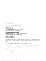
placement
of
jets should take advantage
of any
natural
pumping ability
of the
bearing. This
is
illustrated
in
Fig. 7.17.
Centrifugal
forces
aid in
moving
the oil
through
the
bearing
to
cool
and
lubricate
the
elements. Directing jets into
the
radial gaps between
the
rings
and the
cage
is
beneficial.
The
design
of the
cage
and the
lubrication
of its
surfaces
sliding
on the
rings greatly
effects
the
high-speed performance
of
jet-lubricated bearings.
The
cage
is
usually
the first
element
to
fail
in a
high-
speed bearing with improper lubrication. With
jet
lubrication outer-ring
riding
cages give lower bearing temperatures
and
allow higher speed
capability
than
inner-ring riding
cages.
It is
expected
that
with outer-ring
riding
cages,
where
the
larger radial
gap is
between
the
inner ring
and the
cage,
better
penetration
and
thus
better
cooling
of the
bearing
is
obtained.
Lubricant
jet
velocity
is, of
course, dependent
on the flow
rate
and the
Figure 7.17
Rolling-contact
bearings
263
nozzle
size.
Jet
velocity
in
turn
has a
significant
effect
on the
bearing
temperature. With proper bearing
and
cage design, placement
of
nozzles
and jet
velocities,
jet
lubrication
can be
successfully
used
for
small bore
ball-bearings with
speeds
of
up to 3.0 x
10
6
DN.
Likewise
for
large
bore
ball-
bearings, speeds
to 2.5 x
10
6
DN are
attainable.
7.5.5.
Lubrication
utilizing
under-race passages
During
the mid
1960s
as
speeds
of the
main
shaft
of
turbojet engines were
pushed upwards,
a
more
effective
and
efficient
means
of
lubricating rolling-
element
bearings
was
developed. Conventional
jet
lubrication
had
failed
to
adequately cool
and
lubricate
the
inner-race contact
as the
lubricant
was
thrown
outwards
due to
centrifugal
effects.
Increased
flow
rates only added
to
heat generation
from
the
churning
of the
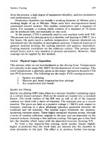
oil. Figure 7.18 shows
the
technique used
to
direct
the
lubricant under
and
centrifically
out, through
holes
in the
inner race,
to
cool
and
lubricate
the
bearing. Some lubricant
may
pass
completely through
and
under
the
bearing
for
cooling
only
as
shown
in
Fig.
7.18.
Although
not
shown
in the figure,
some radial holes
may
be
used
to
supply lubricant
to the
cage rigid lands. Under-race lubricated
ball-bearings
run
significantly
cooler
than identical
bearings
with
jet
lubrication. Applying under-race lubrication
to
small
bore
bearings
(<40mm
bore)
is
more
difficult
because
of the
limited space available
for
the
grooves
and
radial holes,
and the
means
to get the
lubricant under
the
race.
For a
given
DN
value,
centrifugal
effects
are
more severe with small
bearings since
centrifugal
forces vary with
DN
2
.
The
heat generated,
per
unit
of
surface
area,
is
also much higher,
and the
heat removal
is
more
difficult
in
smaller bearings.
Tapered
roller-bearings have been restricted
to
lower
speed applications relative
to
ball-bearings
and
cylindrical roller-
bearings.
The
speed limitation
is
primarily
due to the
cone-rib/roller-end
contact which requires very special
and
careful lubrication
and
cooling
consideration
at
higher speeds.
The
speed
of
tapered roller-bearings
is
limited
to
that which results
in a DN
value
of
approximately
0.5 x
10
6
DN
(a
cone-rib tangential velocity
of
approximately
36ms"
1
)
unless
special
attention
is
given
to the
design
and the
lubrication
of
this very troublesome
Figure
7.18
264
Tribology
in
machine
design
Figure
7.19
contact.
At
higher speeds,
centrifugal
effects
starve
this
critical contact
of
lubricant.
In
the
late 1960s,
the
technique
of
under-race lubrication
was
applied
to
tapered roller-bearings, that
is, to
lubricate
and
cool
the
critical cone-
rib/roller-end contact.
A
tapered roller-bearing with cone-rib
and jet
lubrication,
is
shown schematically
in
Fig. 7.19.
Under-race lubrication
is
quite
successful
in
reducing inner-race temperatures. However,
at the
same
time,
outer-race
temperatures either remain high
or are
higher than those
with
jet
lubrication.
The use of
outer-race cooling
can be
used
to
reduce
the
outer-race temperature
to a
level
at or
near
the
inner-race temperature. This
would
further
add to the
speed capability
of
under-race lubricated bearings
and
avoid large
differentials
in the
bearing temperature that could cause
excessive
internal clearance. Under-race lubrication
has
been
well
de-
veloped
for
larger
bore
bearings
and is
currently being used with many
aircraft
turbine engine
mainshaft
bearings. Because
of the
added
difficulty
of
applying
it, the use
of
under-race
lubrication with small
bore
bearings
has
been minimal,
but the
benefits
are
clear.
It
appears
that
the
application
at
higher
speeds
of
tapered roller-bearings using cone-rib lubrication
is
imminent,
but the
experience
to
date
has
been primarily
in
laboratory
test
rigs.
The use of
under-race lubrication requires holes through
the
rotating
inner
race.
It
must
be
recognized that these holes weaken
the
inner-race
structure
and
could contribute
to the
possibility
of
inner-race
fracture
at
extremely
high speeds. However,
the
fracture
problem exists even without
the
lubrication holes
in the
inner races.
7.5.6.
Mist
lubrication
Air-oil
mist
or
aerosol lubrication
is a
commonly used lubrication method
for
rolling-element bearings. This method
of
lubrication uses
a
suspension
of
fine oil
particles
in air as a fog or
mist
to
transport
oil to the
bearing.
The
fog
is
then condensed
at the
bearing
so
that
the oil
particles
will
wet the
bearing surfaces.
Reclassification
is
extremely important, since
the
small
oil
particles
in the fog do not
readily
wet the
bearing
surfaces.
The
reclassifier
generally
is a
nozzle that accelerates
the
fog,
forming
larger
oil
particles that
more readily
wet the
bearing
surfaces.
Air-oil mist lubrication
is
non-recirculating;
the oil is
passed
through
the
bearing once
and
then discarded. Very
low
oil-flow
rates
are
sufficient
for
the
lubrication
of
rolling-element bearings, exclusive
of the
cooling
function.
This type
of
lubrication
has
been used
in
industrial machinery
for
over
fifty
years.
It is
used very
effectively
in
high-speed, high-precision
machine
tool spindles.
A
recent application
of an
air-oil mist lubrication
system
is in an
emergency lubrication system
for the
mainshaft bearings
in
helicopter turbine engines. Air-oil mist lubrication systems
are
commer-
cially available
and can be
tailored
to
supply
lubricant
from
a
central
source
for
a
large number
of
bearings.
Rolling-contact
bearings
265
7.5.7.
Surface
failure
modes related
to
lubrication
As
discussed earlier,
the
elastohydrodynamic
film
parameter,
A, has a
significant
effect
on
whether satisfactory bearing operation
is
attained.
It
has
been observed that
surface
failure
modes
in
rolling-element bearings
can
generally
be
categorized
by the
value
of
A.
The film
parameter
has
been
shown
to be
related
to the
time percentage during which
the
contacting
surfaces
are
fully
separated
by an oil film. The
practical meaning
of
magnitude
for
lubricated contact operations
is
discussed
in
detail
in
Chapter
2.
Here
it is
sufficient
to say
that
a A
range
of
between
1 and 3 is
where
many rolling element bearings usually operate.
For
this range,
successful
operation
depends
on
additional factors such
as
lubricant/
material interactions, lubricant additive
effects,
the
degree
of
sliding
or
spinning
in the
contact,
and
surface texture other
than
surface
finish
measured
in
terms
of
root mean square (r.m.s.). Surface glazing
or
deformation
of the
asperity peaks
may
occur,
or in the
case
of
more severe
distress superficial pitting occurs. This distress generally occurs when there
is
more sliding
or
spinning
in the
contact such
as in
angular contact ball-
bearings
and
when
the
lubricant/material
and
surface texture
effects
are
less
favourable.
Another type
of
surface
damage related
to the film
parameter
A,
is
peeling,
which
has
been seen
in
tapered roller-bearing raceways. Peeling
is a
very
shallow
area,
uniform
in
depth
and
usually less than
0.013
mm.
Usually this
form
of
distress could
be
eliminated
by
increasing
the A
value.
In
practical
terms
it
means
the
improvement
in
surface
finish and the
lowering
of the
operating temperature.
To
preclude surface distress
and
possible early
rolling-element bearing
failure,
A
values less
than
3
should
be
avoided.
7.5.8.
Lubrication effects
on
fatigue life
The
elastohydrodynamic
film
parameter,
A,
plays
an
important role
in the
fatigue
life
of
rolling element bearings. Generally, this
can be
represented
in
the
form
of the
curve shown
in
Fig. 7.20.
It is
worth noting
that
the
curve
extends
to
values
of
less than
1.
This implies that even though
A
is
such that
significant
surface distress could occur, continued
operation
would result
in
surface-initiated
spalling
fatigue.
The
effects
of
lubrication
on
fatigue
life
have been extensively studied. Life-correction factors
for the
lubricant
effects
are now
being used
in
sophisticated computer programs
for
analysis
of
the
rolling-element
bearing performance.
In
such programs,
the
lubricant
film
parameter
is
calculated,
and a
life-correction
factor
is
used
in
bearing-
life
calculations.
Up to
now,
research
efforts
have concentrated
on the
physical
factors involved
to
explain
the
greater scatter
in
life-results
at low
A
values.
Material/lubricant chemical interactions, however, have
not
been
adequately
studied. From decades
of
boundary lubrication studies,
how-
ever,
it is
apparent that chemical
effects
must play
a
significant
role where
there
is
appreciable
asperity interaction.
Figure 7.20
266
Tribology
in
machine
design
7.5.9.
Lubricant
contamination
and
filtration
It
is
well
recognized that
fatigue
failures
which occur
on
rolling-element
bearings
are a
consequence
of
competitive
failure
modes developing
primarily
from
either
surface
or
subsurface
defects.
Subsurface initiated
fatigue,
that which originates
slightly
below
the
surface
in a
region
of
high
shearing
stress,
is
generally
the
mode
of
failure
for
properly designed,
well
lubricated,
and
well-maintained rolling-element bearings. Surface initiated
fatigue,
often
originating
at the
trailing edge
of a
localized
surface
defect,
is
the
most prevalent mode
of
fatigue
failure
in
machinery where strict
lubricant
cleanliness
and
sufficient
elastohydrodynamic
film
thickness
are
difficult
to
maintain.
The
presence
of
contaminants
in
rolling-element
systems
will
not
only increase
the
likelihood
of
surface-initiated
fatigue,
but
can
lead
to a
significant
degree
of
component surface distress. Usually
the
wear rate increases
as the
contarninant
particle size
is
increased. Further-
more,
the
wear process
will
continue
for as
long
as the
contaminant particle
size
exceeds
the
thickness
of the
elastohydrodynamic
film
separating
the
bearing surfaces. Since this
film
thickness
is
rarely greater than
3
microns
for
a
rolling contact component, even extremely
fine
contaminant particles
can
cause some damage. There
is
experimental evidence showing
that
80 to
90 per
cent reduction
in
ball-bearing
fatigue
life
could occur when
contaminant particles were continuously
fed
into
the
recirculation lubri-
cation system. There
has
been
a
reluctance
to use fine filters
because
of the
concern that
fine
lubricant
filtration
would
not
sufficiently
improve
component
reliability
to
justify
the
possible increase
in the
system
cost,
weight
and
complexity.
In
addition
it is
usually presumed that
fine filters
will
clog more quickly, have
a
higher pressure
drop
and
generally require
more maintenance than currently used
filters.
7.5.10.
Elastohydrodynamic
lubrication
in
design
practice
Advances
in the
theory
of
elastohydrodynamic lubrication have provided
the
designer with
a
better understanding
of the
mechanics
of
rolling contact.
There
are
procedures based
on
scientific
foundations which make possible
the
elimination
of
subjective experience
from
design decisions. However,
it
is
important
to
know both
the
advantages
and the
limitations
of
elastohydrodynamic lubrication theory
in a
practical design context.
There
are a
number
of
design procedures
and
they
are
summarized
in
Fig.
7.21.
A
simple
load
capacity
in a
function
of
fatigue
life
approach
is
used
by
the
designers
to
solve
a
majority
of
bearing application problems.
The
lubricant
is
selected
on the
basis
of
past
experience
and the
expected
operating temperature. Elastohydrodynamic lubrication principles
are not
commonly utilized
in
design procedures. However,
in
special non-standard
cases,
design procedures
based
on the ISO
life-adjustment
factors
are
used.
These procedures allow
the
standard estimated
life
to be
corrected
to
take
into account special reliability, material
or
environmental requirements.
Occasionally,
a
full
elastohydrodynamic lubrication analysis coupled with
Rolling-contact
bearings
267
Figure
7.21
experimental
investigation
is
undertaken
as, for
instance,
in the
case
of
very
low
or
very high speeds
or
particularly demanding conditions.
In
this
section only
a
brief outline
of the ISO
design procedures
is
given.
If
required,
the
reader
is
referred
to the ISO
Draft International
Standard
281-Part
1
(1975)
for
further
details.
An
adjusted rating
life
L is
given
as
or
where
a^
is the
life-correction factor
for
reliability,
a
2
is the
life-correction
factor
for
material
and
a
3
is the
life-correction factor
for
operating
conditions.
The
reliability factor
has
been used
in
life
estimation procedures
for a
number
of
years
as a
separate calculation when other than
90 per
cent
reliability
was
required.
The ISO
procedure uses
«i
in the
context
of
material
and
environmental factors. Therefore, when
L
na
=
L
10
,
0i
= l,
which
means
the
life
of the
bearing with
90 per
cent probability
of
survival
and 10 per
cent
probability
of
failure.
Factors
accounting
for the
operating conditions
and
material
are
very
specific
conceptually
but
dependent
in
practice.
The
material factor takes
account
of the
improvements made
in
bearing steels since
the
time when
the
original
ISO
life
equation
was set up. The
operating condition factor
refers
to the
lubrication conditions
of the
bearing which
are
expressed
in
terms
of
the
ratio
of
minimum
film
thickness
to
composite surface roughness.
In
this
way
the
conditions under which
the
bearing operates
and
their
effect
on the
bearing's
life
are
described.
In
effect,
it is an
elastohydrodynamic
lubri-
cation factor with
a
number
of
silent assumptions such
as;
that
operating
temperatures
are not
excessive, that cleanliness conditions
are
such
as
would
normally apply
in a
properly sealed bearing
and
that there
is no
serious misalignment. Both factors, however, are,
to a
certain extent,
interdependent variables which
means
that
it is not
possible
to
compensate
for
poor
operating conditions merely
by
using
an
improved material
or
vice
268
Tribology
in
machine design
versa.
Because
of
this interrelation, some rolling-contact bearing manu-
facturers
have employed
a
combined
factor
a
2
i,
to
account
for
both
the
material
and the
operating condition
effects.
It
has
been
found
that
the DN
term
(D is the
bearing
bore
and N is the
rotational speed)
has a
dominating
effect
on the
viscosity required
to
give
a
specified
film
thickness.
In a
physical sense this
can be
regarded
as
being
a
shear velocity
across
the oil film.
Before
the
introduction
of
elastohydrody-
namic
lubrication there
was a DN
range outside which special care
in
bearing selection
had to be
taken. This
is
still true, although
the
insight
provided
by
elastohydrodynamic analysis makes
the
task
of the
designer
much
easier.
The DN
values
in the
range
of
10000
and
500000
may be
regarded
as
permitting
the use of the
standard
life
calculation procedures
where
the
adjustment factor
for
operating conditions works satisfactorily.
It
should
be
remembered that
the
standard
life
calculations mean
a
clean
running
environment
and no
serious misalignment.
In
practice, these
requirements
are not
often
met and
additional experimental
data
are
needed. However,
it can be
said
that elastohydrodynamic lubrication
theory
has
confirmed
the use of the DN
parameter
in
rolling contact
bearing design.
7.6.
Acoustic
emission
Noise produced
by
rolling-element bearings
may
usually
be
traced back
to
in
rolling-contact
the
poor
condition
of the
critical rolling surfaces
or
occasionally
to an
bearings
unstable cage. Both
of
these parameters
are
dependent upon
a
sequence
of
events
which start with
the
design
and
manufacture
of the
bearing
components
and
ends with
the
construction
and
methods
of
assembly
of the
machine
itself.
The
relative importance
of the
various causes
of
noise
is a
function
of
machine
design
and
manufacturing route
so
that each type
of
machine
is
prone
to a
few
major causes.
For
example,
on
high-speed machines, noise
levels
will
mostly depend
on
basic running errors,
and
parameters such
as
bearing seating alignment
will
be of
primary importance.
Causes
of
bearing
noise
are
categorized
in
terms
of:
(i)
inherent sources
of
noise;
(ii)
external
influences.
Inherent sources include
the
design
and
manufacturing quality
of the
bearings, whereas external influences include distortion
and
damage,
parameters which
are
mostly dependent
on the
machine design
and the
method
of
assembly. Among
the
ways used
to
control bearing noise
we can
distinguish:
(i)
bearing
and
machine design;
(ii)
precision;
(iii)
absorption
and
isolation.
7.6.1.
Inherent
sources
of
noise
Inherent noise
is the
noise produced
by
bearings under radial
or
misaligning
loads
and
occurs even
if the
rolling surfaces
are
perfect. Under
Rolling-contact bearings
269
these conditions applied loads
are
supported
by a few
rolling elements
confined
to a
narrow load region (Fig. 7.22).
The
radial position
of the
inner
ring
with respect
to the
outer ring depends
on the
elastic deflections
at the
rolling-element raceway
contacts.
As the
position
of the
rolling elements
change with respect
to the
applied load vector,
the
load
distribution
changes
and
produces
a
relative movement between
the
inner
and
outer
rings.
The
movements take
the
form
of a
locus, which under radial load
is
two-dimensional
and
contained
in a
radial
plane; whilst under misalign-
ment,
it is
three-dimensional.
The
movement
is
also periodic with
a
base
frequency
equal
to the
rate
at
which
the
rolling elements pass through
the
load region. Frequency analysis
of the
movement yields
a
basic
frequency
and a
series
of
harmonics.
For a
single-row radial ball-bearing with
an
inner-ring
speed
of
ISOOr.p.m.,
a
typical ball pass rate
is
100
Hz and
significant
harmonics
to
more than
500 Hz can be
generated.
7.6.2.
Distributed
defects
on
rolling
surfaces
The
term, distributed defects,
is
used here
to
describe
the finish and
form
of
the
surfaces
produced
by
manufacturing
processes
and
such defects
constitute
a
measure
of the
bearing quality.
It is
convenient
to
consider
surface
features
in
terms
of
wavelength
compared
to the
Hertzian
contact
width
of the
rolling element-raceway contacts.
It is
usual
to
form
surface
features
of
wavelength
of the
order
of the
contact
width
or
less roughness
whereas longer-wavelength
features
waviness. Both these terms
are
illustrated
in
Fig. 7.23.
7.6.3.
Surface
geometry
and
roughness
The
mechanism
by
which short-wavelength features produce significant
levels
of
vibration
in the
audible range
is as
follows.
Under normal
conditions
of
load, speed
and
lubrication
the
rolling contacts deform
elastically
to
produce
a
small
finite
contact
area
and a
lubricating
film is
generated between
the
surfaces. Contacts widths
are
typically
50-500
jum
depending
on the
bearing
load
and
size, whereas lubricating
film
thick-
nesses
are
between
0.1 and
0.4
nm
for a
practical range
of
operating
conditions.
Roughness
is
only likely
to be a
significant factor
and a
source
of
vibration when
the
asperities break through
the
lubricating
film and
contact
the
opposing
surface.
The
resulting
vibration
consists
of a
random
sequence
of
small impulses which excite
all
natural modes
of the
bearing
and
supporting
structure.
Natural
frequencies which
correlate
with
the
mean impulse rise time
or the
mean interval between impulses
are
more
strongly excited than others.
The
effects
of
surface
roughness
are
predomin-
ant at
frequencies above
the
audible range
but are
significant
at
frequencies
as low as
sixty
times
the
rotational speed
of the
bearing.
The
ratio
of
lubricant
film
thickness
to
composite
r.m.s.
surface
roughness
is a key
parameter which indicates
the
degree
of
asperity
interaction.
If it is
assumed that
the
peak height
of the
asperities
is
only
Figure 7.22
Figure 7.23
270
Tribology
in
machine
design
three times
the
r.m.s. level, then
for a
typical lubricant
film
thickness
of
0.3
^m,
surface
finishes
better than
0.05/^m
are
required
to
achieve
a low
probability
of
surface-surface
interaction.
Waviness
For the
longer-wavelength surface features, peak curvatures
are low
compared
to
that
of the
Hertzian contacts
and
hence rolling motion
is
continuous with
the
rolling elements
following
the
surface
contours.
The
relationship between
the
surface geometry
and
vibration level
is
complex,
being dependent upon bearing
and
contact geometry
as
well
as the
conditions
of
load
and
speed.
The
published theoretical models aimed
at
predicting
bearing vibration levels
from
the
surface waviness measurements
have been successful only
on a
limited scale. Waviness produces vibration
at
frequencies
up to
approximately
300
times rotational speed
but is
predominant
at
frequencies below about
60
times rotational speed.
The
upper limit
is
attributed
to the finite
area
of the
Hertzian contacts which
average
out the
shorter-wavelength features.
In the
case
of two
discs
in
rolling
contact,
the
deformation
at the
contact averages
out the
simple
harmonic waveforms over
the
contact width.
Bearing
quality
levels
The finish and
form
of the
rolling surfaces, largely determine
the
bearing
quality
but
there
are no
universally
accepted
standards
for
their control.
Individual
bearing manufacturers
set
their
own
standards
and
these vary
widely.
Vibration testing
is an
effective
method
of
checking
the
quality
of
the
rolling surfaces
but
again there
is no
universal standard
for
either
the
test
method
or the
vibration limits.
At
present there
are a
number
of
basic
tests
in use for
measuring bearing vibration,
of
these
the
method referred
to
by
the
American Military Specification
MIL B
17913D
is
perhaps
the
most widely used.
7.6.4.
External
influences
on
noise
generation
There
are a
number
of
external factors responsible
for
noise generation.
Discrete defects usually
refer
to a
wide range
of
faults,
examples
of
which
are
scores
of
indentations, corrosion pits
and
contamination. Although these
factors
are
commonplace, they only occur through neglect and,
as a
consequence,
are
usually large
in
amplitude compared
to
inherent rolling
surface
features. Another frequent
source
of
noise
is
ring distortion.
Mismatch
in the
precision between
the
bearing
and the
machine
to
which
it
is
fitted, is a
fundamental problem
in
achieving quiet running. Bearings
are
precision
components, roundnesses
of
2/j.m
are
common
and
unless
the
bearing seatings
on the
machines
are
manufactured
to a
similar precision,
low
frequency vibration levels
will
be
determined more
by
ring distortion,
after
fitting,
than
by the
inherent waviness
of the
rolling surfaces.
Bearings which
are too
lightly
loaded
can
produce high vibration levels.
Rolling-contact bearings
271
A
typical example
is the
sliding
fit,
spring preloaded bearing
in an
electric
motor where spring loads
can
barely
be
sufficient
to
overcome normal
levels
of
friction
between
the
outer ring
and the
housing.
A
certain preload
is
necessary
to
seat
all of the
balls
and to
ensure
firm
rolling contact, unless
this
level
of
preload
is
applied, balls
will
intermittently skid
and
roll
and
produce
a
cage-ball
instability. When this
occurs,
vibration levels
may be
one or
even
two
orders
of
magnitude higher than that normally associated
with
the
bearing. Manufacturers catalogues usually give
the
values
of the
minimum
required preload
for
single radial ball-bearings.
7.6.5.
Noise
reduction
and
vibration control
methods
Noise reduction
and
vibration control problems
can be
addressed
first by
giving
some consideration
to the
bearing type
and the
arrangement.
The
most important factors
are
skidding
of the
rolling elements
and
vibration
due
to
variable compliance. These
two
factors
are
avoided
by
using single
row
radial ball-bearings
in a fixed-free
arrangement with
the
recommended
level
of
preload applied through
a
spring washer. When this arrangement
is
already
used, secondary improvements
in the
source
of
vibration levels
may
be
achieved
by the
selection
of
bearing designs which
are
insensitive
to
distortion
and
internal
form
errors.
The
benefit
of
this
is
clearly seen
at
frequencies
below
sixty
times
the
rotational speed.
The
ball load variation
within
the
bearing
is a key
issue
and the
problem
of
low-frequency
vibration
generation would disappear
if at all
times
all
ball loads were equal. There
are
many
reasons
for the
variation
in
ball
loads,
for
instance, bearing ring
distortion, misalignment, waviness errors
of
rolling surfaces
all
contribute
to
load
fluctuation.
Design studies have shown
that
for
given levels
of
distortion
or
misalignment, ball load variation
is a
minimum
in
bearings
having
a
minimum contact angle under thrust load. Significant reduction
in
low-frequency
vibration levels
can be
achieved
by
selecting
the
clearance
band
to
give
a
low-running clearance when
the
bearing
is fitted to a
machine. However,
it is
important
to
bear
in
mind that running
a
bearing
with
no
internal clearance
at all can
lead
to
thermal instability
and
premature
bearing
failure.
Thus,
the
minimum
clearance
selection
should
therefore
be
compatible
with
other design requirements. Another import-
ant
factor influencing
the
noise
and the
vibration
of
rolling-contact
bearings
is
precision. Rolling-element bearings
are
available
in a
range
of
precision
grades
defined
by ISO
R492. Although only
the
external
dimensions
and
running errors
are
required
to
satisfy
the ISO
specification
and finish of the
rolling
surfaces
is not
affected
it
should
be
noted,
however,
that
the
manufacturing equipment
and
methods required
to
produce
bearings
to
higher standards
of
precision generally result
in a
higher
standard
of finish. The
main advantage
of
using precision bearings
is
clearly
seen
at
frequencies below
sixty
times rotational speed where improvements
in
basic running errors
and the
form
of the
rolling surfaces have
a
significant
effect.
It is
important
to
match
the
level
of
precision
of the
machine
to the
bearing, although
it
presents
difficulties
and is a
common cause
of
noise.
272
Tribology
in
machine
design
Accumulation
of
tolerances which
is
quite usual when
a
machine
is
built
up
from
a
number
of
parts
can
result
in
large misalignments between housing
bores.
The
level
of
noise
and
vibration produced
by a
rolling-contact bearing
is
an
extremely
good
indicator
of its
quality
and
condition. Rolling bearings
are
available
in a
range
of
precision grades
and the
selection
of
higher
grades
of
precision
is an
effective
way to
obtain
low
vibration levels,
particularly
in the
low-frequency
range.
It
should
be
remembered, however,
that
the
machine
to
which
the
bearing
is
going
to be
fitted
should
be
manufactured
to a
similar level
of
precision.
References
tO
Chapter
7 1. W. K.
Bolton.
Elostohydrodynamics
in
Practice; Rolling contact
fatigue
performance
testing
of
lubricants. London: Institute
of
Petroleum, 1977.
2.
T. A.
Harris. Rolling Bearing Analysis.
New
York: Wiley, 1966.
3.
A.
Fogg
and J. S.
Webber.
The
lubrication
of
ball bearings
and
roller bearings
at
high
speed.
Proc.
Instn
Mech.
Engrs,
169
(1953),
87-93.
4.
J. H.
Harris.
The
lubrication
of
roller bearings. London: Shell
Max and
B.P.,
1966.
5.
F.
Hirano. Motion
of a
ball
in an
angular contact bearing. Trans.
ASLE,
8
(1965),
101-8.
6.
F.
Hirano
and H.
Tanon.
Motion
of a
ball
in a
ball bearing. Wear,
4
(1961),
324-32.
7.
C. T.
Walters.
The
dynamics
of
ball bearings. Trans.
ASME,
93
(1971),
167-72.
8
Lubrication
and
efficiency
of
involute gears
8.1. Introduction
Because
it is
assumed that
the
reader already
has an
understanding
of the
kinematics, stress analysis
and the
design
of
gearing,
no
further
presen-
tation
of
these topics
will
be
given
in
this chapter. Instead, prominent
attention
will
be
given
to
lubrication
and
wear problems, because
the
successful
operation
of
gears requires
not
only that
the
teeth
will
not
break,
but
also that they
will
keep
their
precise geometry
for
many hours, even
years
of
running.
The
second topic covered
in
this chapter
is the
efficiency
of
gears.
It is
customary
to
express
the
efficiencies
of
many power transmitting
elements
in
terms
of a
coefficient
of
friction.
A
similar approach
has
been
adopted here.
In
order
to
arrive
at
sensible solutions
a
number
of
simplifying
assumptions
are
made. They
are:
(i)
perfectly
shaped
and
equally spaced involute teeth;
(ii)
a
constant normal pressure
at all
times between
the
teeth
in
engagement;
(hi)
when
two or
more pairs
of
teeth carry
the
load simultaneously,
the
normal pressure
is
shared equally between them.
8.2. Generalities
of If two
parallel curved
surfaces,
such
as the
profiles
of
meshing spur gear-
gear tribodesign
teeth, made
of
a
truly rigid material, were pressed together they would make
contact along
a
line,
which implies that
the
area
of
contact would
be
zero,
and the
pressure
infinite.
No
materials
are
rigid, however,
so
deformation
of
an
elastic nature occurs,
and a finite,
though small
area,
carries
the
load.
The
case
of two
cylinders
of
uniform
radii
RI
and
R
2
was
solved
by
Hertz.
If
we
take
the
case
of two
steel cylinders
for
which
v =
0.286 then
the
maximum
compressive stress
is
given
by
where
P is the
compressive load
per
unit length
of the
cylinders
and E is the
equivalent
Young modulus.
If the
radius
of
relative curvature
R of the
cylinders
is
defined
as
I//?!
+
1/7?
2
then
It
should
be
noted that this stress
is one of the
three compressive stresses,
274
Tribology
in
machine design
and as
such
is
unlikely
to be an
important
factor
in the
failure
of the
material.
The
maximum shear stress occurs
at a
small depth inside
the
material,
and has a
value
of
0.3p
max
;
at the
surface,
the
maximum shear
stress
is
0.25p
max
.
However, when sliding
is
introduced,
a
tangential stress
field due to
friction
is
added
to the
normal load.
As the
friction
increases,
the
region
of
maximum shear stress (located
at
half
the
contact area radius
beneath
the
surface),
moves upwards
whilst
simultaneously
a
second region
of
high yield stress develops
on the
surface
behind
the
circle
of
contact.
The
shear stress
at the
surface
is
sufficient
to
cause
flow
when
the
coefficient
of
friction
reaches about 0.27. These stresses
are
much more
likely
to be
responsible
for the
failure
of the
gear teeth.
The
important point
for the
designer
at
this stage
is
that each
of
these stresses
is
proportional
to
p
max
,
and
therefore
for any
given material
are
proportional
to
-JP/R.
For
several reasons, however, this result cannot
be
directly applied
to
gear teeth.
The
analysis assumes
two
surfaces
of
constant radii
of
curvature,
and an
elastic homogeneous isotropic
stress-free
material. First,
a
^,car
tooth
profile
has a
continuously varying radius
of
curvature,
and the
importance
of
this departure
from
the
assumption
may be
emphasized
by
considering
the
case
of an
involute tooth where
the
profile starts
at the
base
circle.
The
radius
of
curvature,
say
R
lf
is at all
times
the
length
of the
generating
tangent,
so at
this point
it is,
from
a
mathematical point
of
view,
zero;
but it
remains zero
for no finite
length
of the
involute curve, growing rapidly
as we
go up the
tooth
and
having
an
unknown value within
the
base circle.
If
contact were
to
occur
at
this point
the
stress would
not be
infinite,
as an
infinitely
small distortion would cause
the
load
to be
shared
by the
adjoining
part
of the
involute profile,
so
that there would
be a finite
area
of
contact. Clearly,
the
Hertz analysis
is
rather inapplicable
at
this
point;
all
that
can be
said
is
that
the
stresses
are
likely
to be
extremely high.
In the
regions where contact between well-designed gear teeth
does
occur
the
rate
of
change
of
R^
is
much less rapid,
and it is not
unreasonable
to
take
a
mean
value
at any
instant
for the
short length
in
which
we are
interested.
Second,
the
assumption that
the
material
is
elastic
will
certainly break
down
if the
resulting shear stress exceeds
the
shear yield strength
of the
material.
The
consequences
are
quite beyond
our
ability
to
predict them
mathematically.
We
might manage
the
calculations
if one
load
application
at one
instant were
all we had to
deal
with;
but the
microscopic plastic
flow
which
then occurred would completely upset
our
calculations
for
contact
at
the
next point
on the
tooth profile
and so on. The
situation when
the
original contact recurred would
be
quite
different;
and we
have
to
deal with
millions
of
load cycles
as the
gears revolve.
All
that
can be
said
is
that
the
repeated plastic
flow is
likely
to
lead
to
fatigue failure,
but
that
it
will
not
necessarily
do so,
since
the
material
may
perhaps
build
up a
favourable
system
of
residual stress,
and
will
probably work-harden
to
some extent.
If
such
a
process does
go on
then there
is no
longer
a
homogeneous isotropic
stress-free
material.
Third, gears which
are
transmitting more than
a
nominal power must
be
lubricated.
The
introduction
of a
lubricating
film
between
the
surfaces
Lubrication
and
efficiency
of
involute gears
275
might
be
expected
to
alter
the
situation drastically,
but it
does not, simply
because
the oil film
assumes
the
form
of an
extremely thin
film of
almost
constant thickness.
In
view
of all
these
qualifying
remarks,
it is
hardly
to be
expected that
we
could design gear teeth.on
the
basis that
the
maximum shear stress
is
equal
to
0.3/?
max
and has to
equate
to the
shear strength
of the
material
in
fatigue.
Nevertheless,
the
Hertz analysis
is of
vital qualitative value
in
indicating
the
parameter P/R, which,
for any
given material,
can be
taken
as a
criterion
of
the
maximum stress,
the
actual value
to be
allowed being determined
experimentally.
lgure
' In
order
to
proceed,
we
have
to
determine
the
minimum value
of
R
when
only
a
single pair
of
teeth
is in
contact,
as
shown
in
Fig.
8.1.
It is
known that
for
involute teeth
the
radius
of
curvature
is the
length
of the
generating
tangent,
so,
with
reference
to
Fig. 8.1,
we can
write
for
contact
at X
R
will
have
a
minimum value
at
either
E or
F,
depending
on
which
is
nearer
the
adjoining
base
circle.
In
this
case
the
critical
point
is E, and R can be
calculated.
If the
permissible
surface
stress factor determined experiment-
ally
is
denoted
by
S
c
,
then
and
the
permissible tangential load
at the
pitch circle
on a
unit width
of the
tooth
will
be
Again,
as in the
case
of
bending stresses
the
need,
for the
individual designer,
to
work
out
each particular case
is
obviated
by the
provision
of a
factor
Z
which
corresponds
to
(Rcos</>)
for the
meshing teeth
of
module
1, and a
speed factor
X
c
accounting
for
impact
and
dynamic loads.
In
fact,
tables
containing
Z and
X
c
,
given
in
many
books
on
gears,
are
based
on a
slightly
more empirical approach, which suggests that
(R)
0
'
8
gives
better
agreement
with
practice than
(R)
1
°. The final
simple
form
of the
critical factor
S
c
for
surface
wear
is
where
K
is not
directly proportional
to
(1/m)
but to
(1/m)
0
'
8
,
where
m
denotes module. Values
of
S
c
for
commonly used gear materials
can be
found
in
books
on
gears.
8.3.
Lubrication
There
are
three clearly distinguishable regimes
of
operation
for
gears with
regimes
regard
to
lubrication. They
may be
described
and
defined
as
follows:
(i)
Boundary lubrication. This regime
of
lubrication
is
characterized
by a
velocity
so low
that
virtually
no
elastohydrodynamic
lubricating
film
276
Tribology
in
machine design
is
formed between
the
surfaces
in
contact.
The
friction
and
wear
is
mainly
controlled
by the
adsorbed
surface
film, a
few
Angstroms thick,
formed
by the
lubricant
and its
additives.
(ii)
Mixed lubrication.
The
mixed
lubrication
regime
is
predominant when
the
velocity
of the
gears
is
sufficient
to
develop
a
lubricating
film but its
thickness
does
not
provide
full
separation
of the
contacting surfaces.
As
a
result
of
that, direct contact between
the
highest asperities takes
place which
may
lead
to
accelerated running-in.
The
magnitude
of the
frictional
force
and the
rate
of
wear
are
significantly
lower than
in the
case
of
boundary lubrication.
(iii)
Thick
film
lubrication. When
the
speed
of the
gears attains
a
sufficiently
high value,
an
elastohydrodynamic
film is
developed,
the
thickness
of
which
is
adequate
to
separate completely
the
surfaces
of
two
teeth
in
mesh.
In
principle
all the
friction
resistance comes
from
the
shearing
of
the
elastohydrodynamic
film.
There
is
practically
no
wear
if
a
small amount
of
initial wear during running-in
is
ignored.
The
only
potential sources
of
wear
in
this lubrication regime
are
those
due to
abrasive particles contaminating
the oil and the
surface
fatigue
resulting
in
pitting. Each
of the
lubrication regimes
can be
assigned
a
characteristic value
of
friction
coefficient.
In
boundary lubrication,
a
friction coefficient
as
high
as
0.10-0.20
is not
unusual. However,
when
care
is
taken
of the
surface
finish of the
gear teeth
and a
good
boundary lubricant
is
used,
the
coefficient
of
friction
can be
substan-
tially
reduced
to,
say,
the
0.05-0.10
range. Mixed lubrication
is
characterized
by a
coefficient
of
friction
in the
range
of
0.04-0.07.
Thick
film
lubrication produces
the
lowest
friction
and a
coefficient
of
friction
in the
order
of
0.01-0.04
can be
regarded
as
typical.
The
graph
in
Fig.
8.2
provides
an
illustration
of the
three lubrication regimes
discussed. They
are
defined
in
terms
of the
load intensity
and the
velocity
measured
at the
pitch diameter.
The
load intensity value
employed
is the
^-factor.
The
Q-factor
represents
the
average intensity
of
loading
on the
surface, whereas conventional
stresses
used
in
gear
rating formulae represent
the
worst condition, with allowances made
for
misalignment, tooth spacing error, etc. This
approach
seems
to be
more justifiable
as it
takes into account
the
average conditions rather
than exceptional conditions resulting
from
misalignment
or
spacing
Figure
8.2
Lubrication
and
efficiency
of
involute
gears
277
errors.
Any
unusual
load concentration
will
be
relieved
due to
running-in
and the
average conditions
of
loading
will
prevail.
The
other important variable
is the
velocity measured
at the
pitch
diameter.
The
usual practice
is to use the
relative velocities
of
rolling
and
sliding
in any
analysis,
as
they
are
responsible, among
other
factors,
for
developing
an oil film. In a first
attempt, however, aimed
at finding the
lubrication
regime,
the
velocity
of
rolling
at the
pitch diameter
can be
used.
The
upper
limit
in the
Fig.
8.2
represents
the
approximate highest intensity
of
tooth loading that case-carburized gears
are
able
to
carry.
It
also
represents
the
surface
fatigue
strength upper
limit
for a
relatively
good
design.
It is
well
known that
the
pitting
of
gear teeth
is
markedly influenced
by
the
quality
of the
lubrication.
Under
thick
film
lubrication
conditions
the
S-N
curve characterizing
the
tendency
of
gear teeth
to pit is
quite
flat.
As
the
lubrication changes
from
thick
film to
mixed lubrication
and finally
boundary regime lubrication
the
slope
of the S-N
curve becomes progress-
ively
steeper. Figure
8.3
shows typical
S-N
curves
for
contact stress
expressed
as a
function
of the
number
of
gear
tooth
contacts.
The
data
are
valid
for
hard case-carburized gears (approximate hardness
60HRC).
During
one
full
revolution each gear tooth
is
subjected
to one
load cycle.
The
contact stress
in the
gear teeth
is
proportional
to the
square
root
of
the
tooth load
P. The
relation between
the
load
on the
tooth
and the
number
of
cycles
is
given
by
Figure
8.3
where
P
a
is the
tooth load
for
N
a
cycles before pitting,
P
b
is the
tooth
load
for
N
b
cycles before pitting
and q is the
slope exponent
for
load
versus cycle
fatigue
curve.
The
slopes
of the
curves, plotted
in
Fig. 8.3,
are
defined
by the
exponents
in the
following
equations
boundary lubrication regime,
mixed
lubrication
regime,
full
film
lubrication regime.
278
Tribology
in
machine
design
In
practice
the
specified exponent values
may be
quite
different
depending
on the
load
and
service
life
required, expressed
by the
number
of
load cycles
N.
Besides,
depending
on the
microstructure
of the
material,
the
surface
finish, the
character
of the oil
additives
and
other similar factors,
the
slope
of
the S-N
curve
in a
given lubrication regime
may
change. Thus,
in the
boundary lubrication regime
the
slope
may
vary
from
an
exponent
of as low
as 2 to as
high
as 5. A
mixed lubrication regime
may
vary
in
slope
from
4 to 7.
The
thick
film
lubrication regime
is
usually characterized
by an
exponent
in
the
range
of 8 to 16,
particularly
in the
range
of
10
7
cycles
to
10
12
cycles.
Figure
8.3
should
be
considered
as
representing
the
average data
and the
real application conditions
may
vary considerably
from
that shown
in the
figure.
In
the
case
of
heavy pitting some action should
be
taken
in
order
to
stop
or at
least slow down
the
damaging process. Usually
an oil
with higher
viscosity
provides
the
remedy
by
slowing down
the
pitting
and
creating
the
conditions
for the
pitted surfaces
to
recover. Pitting
is not
particularly
dangerous
in the
case
of
low-hardness gears
and a
moderate amount
of
pitting
is
usually tolerated
in
medium-hardness gears.
The
opposite
is
true
for
hard gears where virtually
no
pitting
can be
tolerated. Work-hardening
of
the
surface material
is
taking place during pitting,
due to
that,
the
surface
is
toughened
and
becomes more resistant
to
pitting.
It is
quite
often
the
case
that
if the
lubrication
of the
gears
is
efficient,
pitting
is a
transient problem
ceasing completely
after
some time.
8.4.
Gear
failure
due
Scuffing
is
usually defined
as
excessive damage characterized
by the
to
scuffing
formation
of
local welds between sliding surfaces.
For
metallic surfaces
to
weld
together
the
intervening
films on at
least
one of
them must become
disrupted
and
subsequently
metal-metal
contact must take place through
the
disrupted
film.
When
two
spheres, modelling
the
asperities
on two flat
surfaces,
are
loaded while
in
contact, they
will
at first
deform elastically.
The
region
of
contact
is a
circle
of
radius
a,
given
by the
Hertz theory discussed
in
Chapter
3.
When
the
load
is
increased, plasticity
is first
reached
at a
point beneath
the
surface,
at
about
0.5a
below
the
centre
of the
circle
of
contact.
The
value
of
the
shear stress depends slightly
on the
Poisson
ratio
but for
most metals
has
a
value
of
about
0.47P
m
,
where
P
m
=
(W/na
2
)
is the
mean pressure over
the
circle
of
contact.
At
this stage
F
m
takes
the
value
1.17,
where
Y is the
yield
stress
of the
softer
metal.
As
the
load
is
increased,
the
amount
of
plastic deformation increases
and
the
mean pressure rises. Eventually
the
whole
of the
material
in the
contact
zone
is in the
plastic state
and at
this
point
the
mean pressure
P
m
acquires
its
maximum
value
of
about
3Y. The
load
corresponding
to
full
plasticity
is
about
150
times that
at the
onset
of
plasticity.
There
is,
therefore,
an
appreciable range
of
loads over which plastic
flow
takes place beneath
the
surface without
it
extending
to the
surface layers
themselves.
In
these conditions, welding does
not
occur
and
this possibility
of
changing
the
surface
profile
by
plastic
flow of the
material beneath, gives
Lubrication
and
efficiency
of
involute gears
279
a
means
of
smoothing
out
surface irregularities without causing excessive
damage. This
is one of the
mechanisms utilized during running-in.
When
sliding
is
introduced, however,
a
tangential stress
field due to
friction
is
added
to the
normal load.
As the
friction
increases
the
region
of
maximum
shear stress moves
from
0.5a
beneath
the
surface upwards whilst,
simultaneously,
a
second region
of
high
yield
stress develops
on the
surface
behind
the
circle
of
contact.
The
shear stress
at the
surface
is
sufficient
to
cause
flow
when
the
coefficient
of
friction
reaches about 0.27. With plastic
deformation
in the
surface
layer
itself,
welding becomes possible.
For a
normal
load
which
just
suffices
to
cause shear
at
0.5a
beneath
the
surface,
an
increase
in the
friction
to 0.5
causes shear over
the
whole area
of
contact
in
considerable
depth. Also,
as the
load increases,
the
coefficient
of
friction
necessary
to
cause
flow in the
surface, decreases. Experiments strongly
suggest
that
scuffing
originates primarily with
an
increase
in the
coefficient
of
friction.
Scuffing
is
usually associated with
poor
lubrication.
As
scuffing
starts,
the
damage
is not
great when
the
oxide
films are
disrupted
and the
metals
first
come into contact. Usually
the
damage builds
up as
sliding proceeds.
At first it is
localized near
the
individual surface
asperities
where
it is
initiated. During
further
motion
the
regions
of
damage
grow,
and
eventually
coalesce
with
a
great increase
in the
scale
of the
deformation.
This could imply that
the
tendency
to
scuff
depends upon
the
amount
of
sliding.
In
spur gears,
for
example,
the
motion
is one of
rolling
at
the
pitch
line
and the
proportion
of
sliding increases
as the
zone
of
contact
moves
away
from
it. It was
observed that
scuffing
occurs away
from
the
pitch
line.
Another
significant
factor
to
consider
is the
speed
of
sliding
as it
directly
influences
the
surface
temperature.
The
temperature rise
is
sensitive
to the
load
but
varies
as the
square root
of the
speed.
The
rise
is
usually greater
for
hard
metals than
for
soft
but it is
most sensitive
of all to the
coefficient
of
friction.
Therefore,
the
maintenance
of low
friction,
through
efficient
lubrication,
is of
prime importance
in
reducing
the
risk
of
scuffing.
The
risk
of
scuffing
could also
be
significantly
reduced
by the
proper
selection
of
gear materials.
The first
rule
is
that identical materials should
not rub
together.
If for
some reason
the
pair
of
metals must
be
chemically
similar,
their hardness should
be
made
different
so
that
the
protective
surface
film on at
least
one of
them remains intact, preventing strong
adhesion. Metallic pairs which exhibit negligible solid solubility,
are
more
resistant
to
welding
and
subsequently
to
scuffing,
then those which
form
a
continuous
series
of
alloys.
The
role
of the
natural surface
films is to
prevent
welding.
If
they
are
hard
and
brittle
and the
metal beneath
is
soft,
the
likelihood
of
them being broken increases
significantly.
The
best
films are
ductile
but
hard enough
to
compete
with
the
underlying metal.
There
are
many
factors
which
may
initiate gear
scuffing
but
only
two of
them
are
really
important.
The first is the
critical temperature
in the
contact
zone
and the
other
is the
critical thickness
of the film
separating
the two
contacting
surfaces.
280
Tribology
in
machine design
8.4.1.
Critical temperature factor
The
idea that
scuffing
is
triggered when
the
temperature
in the
contact zone
exceeds
a
certain
critical temperature
was first
introduced
by
Blok
in
1937.
Failure
of the
lubricant
film due to too
high
a
temperature developed
at the
points
of
real contact between
two
teeth
in
mesh
is
central
to
this
hypothesis.
Contacting surface asperities
form
instantaneous adhesive
junctions
which
are
immediately ruptured because
of the
rolling
and
sliding
of
the
meshing gears. This mechanism usually operates with gear teeth
running
in a
thick
film
lubrication regime.
A
severe
form
of
scuffing
is
usually accompanied
by
considerable wear
and as a
result
of
that
the
teeth become overloaded around
the
pitch line.
A
practical consequence
of
this
is
pitting
in an
accelerated form leading
to
tooth
fracture.
One of the
objectives
the
designer
of
gears must attain
is to
secure their operation without serious
scuffing.
It is
generally accepted that
a
mild
or
light
form
of
scuffing
may be
tolerated, provided
it
stops
and the
gears recover. Simple measures such
as
changing
to a
more
efficient
oil,
operating
the
gears
at
less than service load until
the
completion
of the
running-in
of the
teeth
or
even removing
bad
spots
on
large
teeth
by
hand
can
often
be
very
effective
in
saving
the
gear drive
from
serious
scuffing
problems.
A
commonly used design procedure
to
avoid
scuffing
because
of
excessively
high temperature
in the
contact zone depends
on the flash
temperature estimation which
in
turn
is
compared with
the
maximum
allowable temperature
for a
given oil.
The
approximate formula used
to
estimate
flash
temperature
is
where
T
{
is the flash
temperature index [°C],
T
b
is the
gear bulk
temperature [°C],
b is the
face
width
in
contact [mm],
m is the
module
[mm],
R
a
is the
surface
finish
[/im],
G
c
is the
geometry constant (see
Table
8.1)
and
CD
I
is the
angular velocity
of
pinion.
Table
8.1. Geometry constant
G
c
for
pressure angle
$
=
20°
G
c
pinion
gear
(at
pinion
(number
of
(number
of
G
c
tip)
teeth)
teeth)
(at
gear tip)
0.0184
18 25
-0.0278
0.0139
18 35
-0.0281
0.0092
18 85
-0.0307
0.0200
25 25
-0.0200
0.0144
25 35
-0.0187
0.0088
25 85
-0.0167
0.0161
12 35
-0.0402
0.0101
35 85
-0.0087
Lubrication
and
efficiency
of
involute
gears
281
As
a first
approximation,
the
value
of
P
e
may be
assumed
to be
equal
to
the
full
load
on the
tooth. When certain conditions
are
met, that
is,
spacing
accuracy
is
perfect
and the
profile
of the
tooth
is
very accurate
and
modified,
then
jP
e
may be
taken
to be
equal
to 60 per
cent
of P.
Equation (8.8)
was
formulated
with
the
assumption that
the
tooth
surface
roughness
is in the
range
of 0.5 to
0.7jum.
8.4.2.
Minimum
film
thickness
factor
Figure
8.4
illustrates
the
contact
zone
conditions
on the
gear
teeth when
the
running
velocity
is low and
consequently
the
thickness
of an
elastohydro-
dynamic
film is not
sufficient
to
completely separate
the
interacting
surfaces.
The
idea
of the
minimum thickness
of the
lubricant
film is
based
on
the
premise that
it
should
be
greater than
the
average surface roughness
to
avoid
scuffing.
Conditions facilitating
scuffing
are
created when
the
thickness
of the
lubricant
film is
equal
to or
less than
the
average surface
roughness.
It is
customary
to
denote
the
ratio
of
minimum thickness
of the
film to
surface roughness
by
Figure
8.4
where
R
a
=
(R
l
+
R
2
)/2,R
l
is the
root mean square
(r.m.s.)
finish of the first
gear
of a
pair
and
R
2
is the finish in
r.m.s.
of a
second
gear
of a
pair.
The
minimum thickness
of the
lubricant
film
created between
two
teeth
in
mesh
is
calculated using elastohydrodynamic lubrication theory
de-
veloped
for
line contacts (see
Chapter
6).
Contacting teeth
are
replaced
by
equivalent cylinders (see Chapter
3) and the
elastic equation together with
the
hydrodynamic
equation
are
solved simultaneously. Nowadays,
it is a
rather standard problem which does
not
present
any
special
difficulties.
For
spur
or
helical gears
the
following
approximate formula
can be
recommended
where
L
t
=
lubricant
factor
=
(a£')°-
54
,
a
=
lubricant
pressure-viscosity
coefficient,
E'=
effective
modulus
for a
steel gear set,
v
=
the
Poisson
ratio =0.3
for
steel,
282
Tribology
in
machine design
Knowing
both
the
thickness
of the oil film, eqn
(8.10)
and the
roughness
of
the
gear tooth surfaces,
the
parameter
A
can be
determined.
It is
standard
practice
to
assume
a
thick
film
lubrication regime
and no
danger
of
scuffing,
when
A is
greater than 1.2.
In the
case when
A is
less than 1.0, some steps
should
be
taken
to
secure
the
gear
set
against
a
high probability
of
scoring.
This scoring
is a
direct result
of
insufficient
thickness
of the oil film. The
usual remedy
is to use an oil
containing surface-active additives.
8.5.
Gear
pitting
It
is
not
absolutely necessary
to
have contact between interacting gear teeth
in
order
to
produce wear, provided
the
running time
is
long enough.
The
Hertzian stresses produced
in the
contact zone
of
interacting gear teeth
can
lead
to a
fatigue
which
is
regarded
as a
standard mode
of
failure.
It
takes
the
form
of
pitting;
a pit
being
a
small crater
left
in the
surface
as a
result
of a
fragment
of
metal
falling
out.
The
presence
of a
lubricant does
not
prevent
this,
for
under elastohydrodynamic conditions
the
surface pressure distri-
bution
is
essentially that
found
by
Hertz
for
unlubricated contacts.
It
could
be
argued that pitting
is
caused
by
lubrication
in the
sense that without
lubrication
the
surface would
fail
long before pitting could appear.
However, there
are
some reasons
to
believe that
the
lubricant
is
forced
into
the
surface cracks
by the
passage
of
very high pressure
and the
lubricant
then acts
as a
wedge
to
help
open
up and
extend
the
cracks.
It
is
known
from
experiment that smooth surfaces
pit
less readily.
It was
found
from
tests
run on a
disc machine using
a
small slide/roll ratio, that
increasing
the oil film
thickness, also reduced
the
tendency
to pit and
that
the
ratio
of the
surface roughness
to the oil film
thickness,
was the
dominant
parameter.
The
correlation between
the
number
of
revolutions before
pitting
occurred,
and the
surface roughness
to oil film
thickness ratio, holds
over
a
500-fold variation
in the
above-mentioned ratio.
It
must
be
emphasized, however, that
the
surface roughness measured
was
the
initial value,
and
that
the
roughness when pitting occurred
was
very
much
less. Fatigue
failures
can
originate either
at or
beneath
the
surface
and