CYANIDE in WATER and SOIL: Chemistry, Risk, and Management - Chapter 20 doc
Bạn đang xem bản rút gọn của tài liệu. Xem và tải ngay bản đầy đủ của tài liệu tại đây (553.72 KB, 20 trang )
20
Ambient Temperature
Oxidation Technologies for
Treatment of Cyanide
Rajat S. Ghosh, Thomas L. Theis, John R. Smith, and
George M. Wong-Chong
CONTENTS
20.1 Alkaline Chlorination Technologies 394
20.1.1 Process Description and Implementation 394
20.1.2 Achievable Treatment Levels 395
20.1.3 Design Considerations 396
20.1.4 Cost of the Technology 398
20.1.5 Technology Status 398
20.2 Oxidation Technologies with Ozone and Hydrogen Peroxide 398
20.2.1 Process Description and Implementation 398
20.2.2 Achievable Treatment Levels 403
20.2.3 Design Considerations 403
20.2.4 Cost of the Technology 403
20.2.5 Technology Status 404
20.3 Photocatalytic Oxidation Technology 404
20.3.1 Process Description 404
20.3.2 Achievable Treatment Levels 404
20.3.3 Design Considerations 405
20.3.4 Cost of the Technology 405
20.3.5 Technology Status 405
20.4 INCO’s Air/SO
2
Process 406
20.4.1 Process Description 406
20.4.2 Achievable Treatment Levels 407
20.4.3 Design Considerations 408
20.4.4 Cost of the Technology 408
20.4.5 Technology Status 408
20.5 Technology Screening Matrix and Additional Technologies 408
20.6 Summary and Conclusions 408
References 411
Chemical oxidation at ambient temperatures is perhaps the most common treatment technology for
cyanide in contaminated waters. Oxidation technologies, such as alkaline chlorination and ozonation
perform well for free and weak metal–cyanide complexes (weak acid dissociable cyanide [WAD])
in water, soil slurries, and sludges [1–5]. However, energy-intensive oxidation technologies, such as
393
© 2006 by Taylor & Francis Group, LLC
394 Cyanide in Water and Soil
ambient temperature photocatalytic oxidation are necessary to treat strong metal– cyanide complexes
in water, soil slurries, and sludges [5].
The following ambient temperature oxidation technologies are described in detail in this
chapter:
• Ambient temperature alkaline chlorination
• Ambient temperature oxidation with ozone and hydrogen peroxide
• Photocatalytic oxidation technologies
• INCO’s Air/SO
2
process
These technologies have been applied for the treatment of water, soil slurries, and sludges containing
free cyanide, weak metal–cyanide complexes, or strong metal–cyanide complexes. Descriptions for
the technologies follow, and include the following main features:
• Process description and implementation
• Achievable treatment levels
• Design considerations
• Critical design conditions
• Residuals generated
• Technology complexity
• Cost information
• Status of technology implementation
temperature oxidation technologies.
20.1 ALKALINE CHLORINATION TECHNOLOGIES
20.1.1 P
ROCESS DESCRIPTION AND IMPLEMENTATION
The most widely used technology for the destruction of free cyanide and certain weak metal–cyanide
complexes is chlorineoxidation under alkalineconditions, commonlyknownas alkalinechlorination.
Here, free cyanide and certain weakly complexed metal cyanides (i.e., WAD cyanides), such as
copper, cadmium, and nickel cyanide, are oxidized to cyanate (CNO
−
) and subsequently to carbon
dioxide and nitrogen gas. Chlorine gas or hypochlorite (ClO
−
) is used as the oxidant, and an alkali
(e.g., sodium hydroxide or lime) is used to produce the pH conditions above 9.5 needed to sustain
the oxidation reaction. When chlorine gas is used as the oxidizing agent, the process chemistry is
given by the following reaction [1,6,7]:
CN
−
+2NaOH +Cl
2
→ CNO
−
+2Na
+
+2Cl
−
+H
2
O (20.1)
The above reaction proceeds at significant rates under alkaline conditions (pH 10 and higher)
[8]. Addition of alkali is essential to maintain the proper reaction pH and to prevent the generation
of any toxic cyanogen chloride (CNCl) or HCN gas, which forms at pH < 10 [6]. The oxidation of
cyanide to cyanate is rapid, requiring about 15 to 30 min of contact time and Cl/CN dose of about 3
(on a mass basis). The complete destruction of cyanide can be accomplished by lowering the pH
of the solution after cyanate formation to 9 and addition of excess chlorine. This second reaction
proceeds as follows [7]:
3Cl
2
+2CNO
−
+4NaOH → 2CO
2
+N
2
+2Cl
−
+4Na
+
+4Cl
−
+2H
2
O (20.2)
© 2006 by Taylor & Francis Group, LLC
The chapter concludes with a technology summary matrix (Table 20.7) for all the available ambient
Ambient Temperature Oxidation Technologies 395
TABLE 20.1
Typical Operating Conditions for a Two-Stage Alkaline Chlorination
Process
Chlorine dose NaOH dose Redox Retention
Stage pH (g Cl/g CN) (g NaOH/g CN) potential (mV) time (min)
1 9.5–11 2.7–3.0 3.1–3.4 350–400 30–60
2 8.0–8.5 4.1–4.5 4.2–4.6 600 30–60
Source: Data from Palmer, S.A.K., Breton, M.A., Nunno, T.J., Sullivan, D.M., and
Surprenant, N.F., Metal/Cyanide Containing Wastes: Treatment Technologies, Corp, N.D., Ed.,
Noyes Data Corp., Park Ridge, NJ, 1998.
In cases where a metal–cyanide species is oxidized, the liberated metal generally forms a hydroxide
precipitate under the alkaline conditions of the reaction.
Treatment of thiocyanate (SCN
−
) by alkaline chlorination occurs in the pH range of 10 to 11.5
according to the following reaction:
2SCN
−
+8Cl
2
+20OH
−
→ 2CNO
−
+2SO
−2
4
+16Cl
−
+10H
2
O (20.3)
The alkaline chlorination process for free and WAD cyanide can be operated as a one-or two-step
process in either batch or continuous flow. In the two-step process, the first step is used for oxidation
of cyanide to cyanate; in thesecond step, cyanate is oxidized to carbon dioxide and nitrogen. Cyanate,
however, can also be hydrolyzed to CO
2
and NH
3
by adjusting pH to the 7 to 8 range, which reduces
the chlorine demand.
There is extensive full-scale application of this technology in electroplating and gold mining
operations. Table 20.1 gives typical operating conditions for a two-stage, full-scale continuous flow
alkaline chlorination unit for treating free and WAD cyanide.
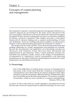
treatment of cyanide in tailings pond decant water [9]. Although the figure shows chlorine gas being
used, this can be replaced by hypochlorite solution, which would eliminate the recirculation pump
and chlorine eductor; however, a hypochlorite solution feed pump would still be required. The hypo-
chlorite feed pump or chlorine gas feed would be oxidation–reduction potential (ORP) controlled and
effluentquality producedby alkalinechlorination systems atfour goldmining operations. It should be
noted thatresidual chlorineis toxic to many speciesin theenvironment and discharge of effluents with
high residual chlorine concentrations can be problematic and, in some instances, will be prohibited.
For the treatment of certain weak metal–cyanide and strong metal–cyanide complexes, modifica-
tions to this process are implemented, including increasing the temperature and retention times in the
reaction vessel [6,10,11]. Details of high temperature alkaline chlorination technology are provided
20.1.2 ACHIEVABLE TREATMENT LEVELS
Weakly complexed metal cyanides are typically reduced to a concentration less than 1 mg/l, while
free cyanide concentrations following alkaline chlorination are usually less than 0.2 mg/l. These
performance levels will depend on chlorine dosage, reaction pH, reaction time, and the general
chlorine demand of the waste. This technology is not applicable for strongly complexed metal
cyanides like iron– or cobalt–cyanide complexes.
© 2006 by Taylor & Francis Group, LLC
Figure 20.1 presents a schematic flow diagram of a typical alkaline chlorination system for the
the lime/alkaline feed would be pH controlled. Tables 20.2 and 20.3 present operating parameters and
under thermal technologies in Chapter 22.
396 Cyanide in Water and Soil
pH ORP
Reactor tank(s)
0.5–1.5 h
pH 10–11.5
Tailings
sump
To tailings pond
Recirculating
pump
Eductor
Chlorine gas or
hypochlorite
Mixing
Solid tails
Lime slurry
Barren solution or
tailing pond water
FIGURE 20.1 Schematic flow diagram of a typical alkaline chlorination system. (Source: Smith, A. and
Mudder, T., The Chemistry and Treatment of Cyanidation Wastes, Mining Journal Books, Ltd., London, 1991.
With permission.)
TABLE 20.2
Operating Parameters for Full-Scale Alkaline Chlorination Operations
Giant
Mosquito Baker Carolin Yellowknife
Parameter Creek mine mine mine mine
Mill capacity (Tpd)
a
100 100 1250 1200
Solids cyanided Ore Ore Concentrate Roaster calcine
Solid feed rate (Tpd)
a
100 100 75 140
Treatment mode Batch Cont. Cont. Cont.
Solution treated Barren Barren Barren Tailings pond
overflow
Solution rate 3 to 5.5 m
3
14.4 m
3
/day 216 m
3
/day 6545 m
3
/day
batches/day
Form of chlorine Gaseous Calcium Gaseous Gaseous
hypochlorite
No. reactor tanks 1 2 1 1
Retention time (h) 6 14 8 0.5
pH 11 11.5 11 11.5
pH control Manual Manual Auto Auto
Chlorine control Manual Manual Manual Manual
a
Tpd = metric tons (tonnes) per day.
Source: Smith, A. and Mudder, T., The Chemistry and Treatment of Cyanidation Wastes, Mining Journal
Books, Ltd., London, 1991. With permission.
20.1.3 DESIGN CONSIDERATIONS
The critical design parameters for alkaline chlorination include chlorine/cyanide (Cl/CN) ratio,
reaction pH, and reaction time. The technology is well suited for treatment up to 5000 mg/l of
© 2006 by Taylor & Francis Group, LLC
Ambient Temperature Oxidation Technologies 397
TABLE 20.3
Performance Data for Full-Scale Alkaline Chlorination of Gold Mill Effluents
Constituents, mg/l
Mine CN
a
T
CN
b
W
CNS Cu Fe Ni Zn As NH
3
TRC
d
Baker
Influent 2000 1900 1100
c
290 2.4 — 740 — — —
Effluent 8.3 0.7 — 5.0 2.8 — 3.9 — — 2800
e
% removal 99.6 99.9 — 98.3 — — 99.5 — — —
Carolin
Influent 1000 710 1900
c
97 150 — 110 — — —
Effluent 170 0.95 — 0.38 53 — 5.8 — — 190
% removal 83 99.9 — 99.6 64.7 — 94.7 — — —
Mosquito Creek
Influent 310 226 330
c
10.0 9.4 — 93 — — —
Effluent 25 0.49 — 0.33 8.0 — 1.4 — — 320
% removal 91.9 98.8 — 96.7 14.9 — 98.5 — — —
Giant Yellowknife
Influent 7.5 7.1 6.3 6.7 <0.1 1.2 0.1 12.1 — —
Effluent 1.3 1.2 1.0 0.09 <0.1 0.7 0.1 — — —
% removal 82.7 85.1 84.1 98.7 — 41.7 — — — —
Polishing pond O/F 0.15 0.09 — 0.03 <0.1 — <0.1 0.14 9.4 1.1
% removal 98 98.7 — 99.6 — — — 99.7 — —
All samples unfiltered.
a
CN
T
= total cyanide by distillation.
b
CN
W
= weak acid dissociable cyanide by ASTM Method C.
c
Analysis not available due to analytical difficulties.
d
TRC = total residual chlorine.
e
Additional chlorine added with a view to destroying cyanide contained in solid tailings slurry.
Source: Smith, A. and Mudder, T., The Chemistry and Treatment of Cyanidation Wastes, Mining Journal Books, Ltd.,
London, 1991. With permission.
free cyanide using batch systems, while continuous processes with flow rates up to 5 gpm can treat
up to 1000 mg/l, with optimal treatment efficiency usually achievable for concentrations below
100 mg/l and influent flow rates up to 100 gpm [6,7,12]. Waste chlorine demand greatly influences
Cl/CN ratio; chlorine demand does not depend only on cyanide content.
The technology is not suitable for waste streams containing strong metal–cyanide complexes,
such as ferro- or ferricyanide and high concentrations of thiocyanates (SCN
−
). Moreover, optimal
efficiency is achieved for influents containing less than 100 mg/l of total suspended solids (TSS),
less than 1000 mg/l of total dissolved solids (TDS), pH levels between 9 and 13, and ORP greater
than 200 mV.
As far as residuals are concerned, metal hydroxide sludges can be generated if the influent stream
contains appreciable amounts of weak metal–cyanide complexes, or metals in other forms. Weaker
complexes that dissociate during the process of oxidation will liberate metal cations, leading to the
formation of metal hydroxides under alkaline pH conditions. Residual chlorine and chloramines are
also generated, which, because of their toxic nature, should be removed by dechlorination prior to
discharge. At pH < 9, generation of CNCl, a toxic gas, as an intermediate during the oxidation of
© 2006 by Taylor & Francis Group, LLC
398 Cyanide in Water and Soil
cyanide to cyanate is a concern. Careful control of pH and ORP should be in place to prevent any
evolution of CNCl gas.
The technologyis relatively easy toimplement andoperate. It requires basicwastewater treatment
unit operations and continuous monitoring of pH to prevent production of CNCl and HCN. Chlorine
gas handlingand leakage pose possible health hazards. If metal hydroxide sludgesare generated, they
may require additional treatment for stabilization prior to disposal. Moreover, the heat of reaction
from chlorine and cyanide decomposition may require some form of temperature control before
the final effluent can be discharged to the sewer.
20.1.4 COST OF THE TECHNOLOGY
Capital costs for a typical 500 gpm system for treating waste streams that contain free and WAD
complexes hasbeen reportedas approximately$300,000 (1990cost basis), withtypical operationand
maintenance (O&M) costsvarying between $5 and $7 per kilogram of cyanide destroyed [6,9,12,13].
20.1.5 TECHNOLOGY STATUS
Alkaline chlorination is a well-established, commerciallypracticed technology with many successful
full-scale applications in place in electroplating and gold mining industries [6,9,12,13]. Prefabricated
chemical feedand monitoringequipment suitablefor implementing thistechnology arecommercially
available. However, some bench-scale testing for a particular application usually is desirable for
determination of optimal Cl/CN dose, pH conditions, and reaction time.
20.2 OXIDATION TECHNOLOGIES WITH
OZONE AND HYDROGEN PEROXIDE
20.2.1 P
ROCESS DESCRIPTION AND IMPLEMENTATION
These processes involve the oxidative destruction of free and WAD forms of cyanide by either
ozone or hydrogen peroxide under alkaline pH (9–11) conditions. Oxidation of cyanide (CN
−
)to
cyanate (CNO
−
) occurs in 10–15 min in the presence of excess ozone under alkaline conditions
(9 < pH < 10) according to the following reaction [14]:
CN
−
+O
3
→ CNO
−
+O
2
(20.4)
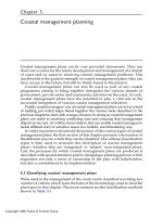
Gurol and Bremen [3] reported a first-order reaction rate coefficient (2600 ± 700 M
−1
sec
−1
) for
constant for ozone decay as a function of total cyanide concentration. As shown in this figure,
the cyanide oxidation rate increases with increase in pH. Rate expressions for ozone oxidation of
cyanide at three different pH values are as follows [3]:
−d[O
3
]/dt = (2600 ±700)[CN
T
]
0.55±0.06
[O
3
] at pH = 11.2 (20.5)
−d[O
3
]/dt = (2700 ±850)[CN
T
]
0.83±0.14
[O
3
] at pH = 9.5 (20.6)
−d[O
3
]/dt = (550 ±200)[CN
T
]
1.06±0.1
[O
3
] at pH = 7.0 (20.7)
The presence ofcopper wasfoundto catalyze thecyanide oxidation processaccording tothe following
reaction [15]:
2Cu
+
+11CN
−
+3O
3
→ 2Cu(CN)
3−
4
+3CNO
−
+3O
2
(20.8)
© 2006 by Taylor & Francis Group, LLC
ozonation of free cyanide at pH 11.2. Figure 20.2 presents the observed pseudo-first-order rate
Ambient Temperature Oxidation Technologies 399
3.0
Phosphate solutions
pH 11.2
1
2.5
2.0
Log k
obs
(sec
– 1
)
1.5
1.0
0.5
0
– 4.0 – 3.0 – 2.0
Log [CN
T
], M
– 1.0 0
pH 9.5
2
pH 7.0
3
1
2
3
FIGURE 20.2 Observed pseudo-first-order rate constant for ozone decay vs. total cyanide concentration on
log scales. (Source: Reprinted with permission from Gurol, M.D. and Bremen, W.H., Environ. Sci. Technol.,
19, 804, 1985. Copyright 1985. American Chemical Society.)
In the presence of excess ozone, cyanate is hydrolyzed to bicarbonate and nitrogen according to the
following reaction [14]:
2CNO
−
+3O
3
+H
2
O → 2HCO
−
3
+N
2
+3O
2
(20.9)
This second stage reaction is much slower than the cyanate formation reaction and is usually carried
out in the pH range of 10 to 12 where the reaction rate is relatively constant. Temperature variation
within the ambient range does not have a significant effect on the reaction rates. However, the use of
ultraviolet (UV) light to enhance radical formation [6] and the presence of copper catalyst [12] have
each been shown to increase the rate of the second stage reaction.
The metal–cyanide complexes of cadmium, copper, nickel, silver, and zinc are readily oxidized
by ozone. For treatment of strong metal–cyanide complexes, such as iron– and cobalt–cyanide,
modifications to the existing process are implemented, including prolonged UV light exposure to
promote photodissociation [4,5]. However, Guroland Holden[15] reportedoxidationof iron–cyanide
complexes in the presence of excess ozone (ozone to iron cyanide ratio of 30:1 on a molar basis)
under laboratory conditions.
Thiocyanate/SCN
−
is readily oxidized by ozone [16]. Layne et al. [16] determined that for
pH > 11, SCN
−
reacts with ozone to form CN
−
and SO
2−
4
, and the free CN
−
is subsequently
oxidized to CNO
−
as shown in reaction (20.4).
© 2006 by Taylor & Francis Group, LLC
Additional discussion of this reaction and the catalytic effect of the copper is provided in Chapter 5.
400 Cyanide in Water and Soil
Hydrogen peroxide provides another alternative in treating free and weakly complexed metal
cyanides in waters and wastewaters. Although H
2
O
2
is a weaker oxidizing agent than ozone
(standard electrode potential of 0.878 V in alkaline solution compared to 1.24 V for ozone under
same solution conditions), cyanide can be fully converted by hydrogen peroxide to ammonia and
carbonate under alkaline conditions, according to the following reactions:
CN
−
+H
2
O
2
→ CNO
−
+H
2
O (20.10)
CNO
−
+H
2
O + OH
−
→ NH
3
+CO
2−
3
(20.11)
The first reaction is optimal in the pH range of 9.5 to 10.5 [8]. The second reaction, however,
is very slow under alkaline condition and increases as pH decreases [17]. The cyanide oxidation rate
also depends onthe excesshydrogen peroxide concentration, cyanide concentration, and temperature.
The reaction rates can also be enhanced by the presence of a metal catalyst, such as copper, which
ultimately reacts with ammonia to form a tetraamino copper complex that is largely nonreactive [8].
Copper-catalyzedhydrogen peroxide oxidationofWADcyanidecomplexes in wastewateris prac-
ticed commonly in the gold mining industry [9]. The destruction of weak metal–cyanide complexes
occurs according to the following reactions:
M(CN)
−2
4
+4H
2
O
2
+2OH
−
Cu catalyst
−→ 4CNO
−
+4H
2
O + M(OH)
2
(s) (20.12)
CNO
−
+2H
2
O −→ NH
+
4
+CO
2−
3
(20.13)
where M is a metal cation, such as Cu or Zn. The copper, which is added as a catalyst or present in
the waste as Cu(CN)
−
2
, can react with strongly complexed Fe(CN)
4−
6
to form an insoluble bimetallic
complex according to the following reaction:
Fe(CN)
4−
6
+2Cu
+2
−→ Cu
2
[Fe(CN)
6
](s) (20.14)
It is customary to add copper sulfate pentahydrate as the catalyst to produce a copper concentration
of about 10 to 20% of the WAD cyanide concentration.
The peroxide dose needed for successful oxidation of cyanide species may be 200 to 450% of
the required amount indicated by stoichiometry [9]. The high peroxide dosage rate is reflective of
the presence of other oxidizable materials in the wastewater that can compete for the peroxide, as
well as the inherent loss of oxidation capacity as some of the peroxide may decompose to oxygen
and water:
2H
2
O
2
−→ O
2
+2H
2
O (20.15)
To reduce these decomposition losses, peroxide stabilizers such as silicate (employed in Degussa’s
SILOX process) and sulfuric acid, which forms peroxymonosulphuric acid (Caro’s acid), have been
developed and deployed with substantial savings over the conventional peroxide process [18].
for cyanide [18]. As shown in this figure, hydrogen peroxide is added to the first reaction tank along
with the influent solution. In the second mixingtank, copper isadded as copper sulfate to catalytically
promote the cyanide oxidation reaction. The supernatant from the second mixing tank then goes to
the third tank, where enough settling of solid sludges (copper–iron–cyanide solids; iron hydroxides)
and increased residence time causes complete removal of cyanide, and cyanide-free supernatant is
discharged into the tailings pond.
tinuous tailings slurry treatment system using hydrogen peroxide at the OK Tedi Mine in Papua,
© 2006 by Taylor & Francis Group, LLC
Figure 20.3 presents a schematic flow diagram of a typical hydrogen peroxide treatment system
Figure 20.4 and Table 20.4 present a schematic flow diagram and performance data for a con-
Ambient Temperature Oxidation Technologies 401
H
2
O
2
storage
Feed pump
To
tailings
pond
Reaction tanks
CuSO
4
catalysts
(if required)
Tailings pulp
or
Barren solution
FIGURE 20.3 Schematic flow diagram of a typical hydrogen peroxide treatment system for cyanide. (Source:
Botz, M. et al., Cyanide Monograph, Mining Journal Books, Ltd., London, 1998. With permission.)
Measuring
cell
Control
unit
Multiplier
Reaction
tank
H O pumps
22
Main tailings stream
Control stream
Redox
pH
H
2
O
2
Control valve
Flow meter
Sample for
analysis
1– 10 mg/l CN
T
<0.3 mg/l WAD CN
Control system
Tailings slurry
1100 m /h
110– 300 mg
/l CN
3
T
Activator CN
Caroate
NaOH
H
2
SO
4
FIGURE 20.4 Schematic flow diagram for the Degussa hydrogen peroxide process at the OK Tedi Mine.
(Source: Smith, A. and Mudder, T., The Chemistry and Treatment of Cyanidation Wastes, Mining Journal
Books, Ltd., London, 1991. With permission.)
New Guinea. Because of the lack of suitable means to determine the necessary dosage of H
2
O
2
quickly and accuratelyenoughto allow efficientuseof thereagent fortreatment oflarge effluent flows,
a continuous automatic titration is implemented in a small sidestream as depicted in Figure 20.4.
The pH of the sidestream is adjusted automatically to a particular value, and a fast-acting strong
oxidizing agent is dosed. The rate of dosage is controlled by a redox measurement carried out in the
presence of a special catalyst (“Activator CN”). Simultaneous to the addition of the strong oxidizing
agent (an aqueous solution of “caroate,” potassium monopersulfate) to the sidestream, H
2
O
2
,ata
concentration of 70% by weight, is added to the main tailings stream via a control valve. The opening
© 2006 by Taylor & Francis Group, LLC
402 Cyanide in Water and Soil
TABLE 20.4
Tailings Slurry Characteristics after Degussa
Hydrogen Peroxide Treatment at OK Tedi Mine
Before H
2
O
2
After H
2
O
2
Parameter Treatment Treatment
Tailings flow 1100 m
3
/h 1100 m
3
/h
Solids content 45% 45%
pH 10.5–11.0 10.2–10.8
Free cyanide 50–100 mg/l Undetectable
WAD cyanide 90–200 mg/l <0.5 mg/l
Total cyanide 110–300 mg/l 1–10 mg/l
Dissolved Cu 50–100 mg/l <0.5 mg/l
Dissolved Zn 10–30 mg/l <0.1 mg/l
Dissolved Fe 1–3 mg/l 1–3 mg/l
Source: Smith, A. and Mudder, T., The Chemistry and Treatment
of Cyanidation Wastes, Mining Journal Books, Ltd., London, 1991.
With permission.
TABLE 20.5
Treatment Performance for Three Hydrogen Peroxide Treatment Plants
Before Treatment (mg/l) After Treatment (mg/l)
CN WAD CN Cu Fe CN WAD CN Cu Fe
Case study #1 19 19 20 <0.1 0.7 0.7 0.4 <0.1
Pond overflow
a
Case study #2 1350 850 478 178 <5 <1 <5 <2
Barren bleed
b
Case study #3 353 322 102 11 0.36 0.36 0.4
d
<0.1
Heap leach solution
c
a
Preliminary plant results from pre-operational test runs.
b
Typical results during first six months of operation.
c
Average of 25 measurements made over 10 days of plant operation.
d
Value dropped from 1.0 to 0.4 over 4 days due to coagulation and settling.
Source: Smith, A. and Mudder, T., The Chemistry and Treatment of Cyanidation Wastes, Mining Journal
Books, Ltd., London, 1991. With permission.
of this valve is controlled by a signal obtained by multiplying the signal from the control unit by
a second signal obtained from a tailings flow meter.
Table 20.5 presents performance data from three other hydrogen peroxide treatment facilities
at gold mining sites. While the data in Tables 20.4 and 20.5 show excellent removal of cyanide
by oxidation and precipitation of metals, it must be recognized that these facilities are only used
for treatment of primary constituents of concern, like cyanide. Hydrogen peroxide treatment does
not affect ammonia, nitrate, or thiocyanate; treatment of these constituents will require additional
treatment units.
Hydrogen peroxide oxidation for free cyanide can also be effective under alkaline conditions,
and in the presence of a metal catalyst (Fe, Al, Ni) or formaldehyde. The patented Kastone
© 2006 by Taylor & Francis Group, LLC
Ambient Temperature Oxidation Technologies 403
Process uses H
2
O
2
and formaldehyde to oxidize free cyanide to cyanate at 49–54
◦
CandatapHof
10–12 [12].
20.2.2 A
CHIEVABLE TREATMENT LEVELS
Free and weakly complexed cyanides are typically reduced to a concentration less than 0.1 mg/l
depending on ozone or hydrogen peroxide dose, reaction pH, and reaction time. The oxidation of
cyanide by ozone and hydrogen peroxide usually occurs rapidly up to cyanate formation. Oxidation
of cyanate by ozone, however, is a slow reaction and cyanate may accumulate in the solution until
cyanide is completely oxidized. Hydrogen peroxide is a weaker oxidant than ozone and requires
greater doses for the same level and rate of cyanide destruction. In addition, with hydrogen per-
oxide, the cyanate oxidation reaction rate increases with decrease in pH and the presence of
copper catalyst. Achievable treatment levels for cyanide using Kastone Process could be as low
as 0.1 mg/l.
20.2.3 DESIGN CONSIDERATIONS
The critical design parameters include ozone/cyanide (O
3
/CN) or H
2
O
2
/CN ratio, reaction pH, and
reaction time. The presence of significant amounts of organic material or reduced inorganic species
can significantly increase the ozone or hydrogen peroxide demand. Full scale oxidation systems
are usually limited to total cyanide concentrations of less than 40 mg/l and with less than 1%
organic matter [6], and are unsuitable for waste streams containing strong metal–cyanide complexes
and high thiocyanate content. Optimal waste stream handling conditions are as follows: TSS <
100 mg/l, TDS < 1000 mg/l, and pH of the stream between 5 and 7. Ozonation is usually most
economical for flows less than 500 gpm. Moreover, this technology requires a continuous supply
of cooling water (typically 4000 l of water per kg of ozone). Similar restrictions are applied for
treatment systems using hydrogen peroxide as the oxidant.
As far as residuals are concerned, metal hydroxide sludges can be generated if an influent stream
contains appreciable amounts of weak metal–cyanide complexes. Moreover, the presence of cyanate
in the product stream may require additional treatment prior to discharge.
The oxidation technologies involving ozone and hydrogen peroxide are more complex than the
alkaline chlorination process. For ozonation, on-site ozone generators, including aircompressors and
oxygen concentrators, are used in addition to the process reactor, along with their dedicated control
systems. Like alkaline chlorination, the technology requires extensive health and safety training for
operators, especially when dealing with a strong oxidizer such as ozone.
The benefits of using ozone over chlorine are: (i) stronger oxidation potential, (ii) on-site genera-
tion resulting in reduced transportation, storage, and handling costs, and (iii) elimination of potential
formation of chlorinated organics. However, on-site generation facilities and power requirements
may incur significant capital and operating costs [19].
20.2.4 COST OF THE TECHNOLOGY
The capital cost of ozone oxidation technology is significantly higher than the alkaline chlorination
process. It requires higher initial cost, related primarily to the on-site ozone generation equipment,
and the need for a continuous supply of cooling water. Capital costs for a typical 500 gpm ozonation
system have been reported as $875,000 (1988 cost basis); typical O&M costs are around $2/kg of
cyanide destroyed [6]. The capital and operating costs associated with hydrogen peroxide systems
are usually lower than ozonation systems of the same scale, but are higher than conventional alkaline
chlorination processes.
© 2006 by Taylor & Francis Group, LLC
404 Cyanide in Water and Soil
20.2.5 TECHNOLOGY STATUS
Ozonation and hydrogen peroxide application are well-established technologies with limited full-
scale applications in place [6], mainly in the mining and electroplating industries. Prefabricated
chemical feedand monitoringequipment suitablefor implementing thistechnology arecommercially
available.
20.3 PHOTOCATALYTIC OXIDATION TECHNOLOGY
20.3.1 P
ROCESS DESCRIPTION
This three-step process involves UV-light-aided photodissociation of metal–cyanide complexes,
including the strong iron– and cobalt–cyanide complexes, to free cyanide. The liberated free cyanide
is further oxidized to CO
2
and NO
−
3
, using either ozone or H
2
O
2
in the presence of a TiO
2
catalyst.
studied in the laboratory, over a wide range of pH conditions, for the purpose of treating waters con-
taminated with iron–cyanide complexes [5,20–24]. The photocatalytic oxidation reaction scheme
for iron–cyanide complexes has been described by Schaefer [22] as follows:
Fe(CN)
3−
6
+3H
2
O + hν → CN
−
+Fe(OH)
3
(s) + 3H
+
+3e
−
(20.16)
CN
−
+oxidant → CNO
−
(20.17)
CNO
−
+oxidant → CO
2
+NO
−
3
(20.18)
As noted previously, ozone provides much more rapid reaction rates than hydrogen peroxide [6],
and the cyanate oxidation reaction is usually slower than the cyanide oxidation and the initial pho-
todissociation reactions. However, UV irradiation in combination with hydrogen peroxide or ozone
results in the formation of OH
•
radicals, which are strong oxidizing agents capable of oxidizing
iron–cyanide complexes.
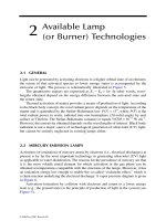
Photocatalytic oxidation may be implemented in one or two stages, and in batch or continuous
flow mode under conditions of ambient temperature and pressure. In a one-stage system, photo-
dissociation and oxidation occur in the same reactor vessel. In a two-stage system, the first stage is
used to photodecompose the iron–cyanide complex under alkaline conditions at a UV wavelength of
350 nm, and the second stage is used for complete oxidation of the free cyanide ion in the presence
oxidation system. Note that an intermediate filtration step is performed to remove any metal oxide
and hydroxides produced under the alkaline pH conditions from free iron and other metals produced
upon photodissociation.
20.3.2 ACHIEVABLE TREATMENT LEVELS
Under bench-scale laboratory conditions, Schaefer [22] achieved complete photocatalytic oxidation
of an aluminum reduction wastewater stream containing 64 to 85 mg/l of soluble ferrocyanide
in2htoless than 0.5 mg/l in the effluent. However, complete destruction of cyanide to carbon
dioxide did not occur, and the reaction sequence slowed in the second stage (Equation [20.17])
with the formation of cyanate. The first-order rate constant for the dissociation of ferrocyanide at
an ozone dose of 865 mg/min was 0.0332 min
−1
. To determine the effect of variable ozone dosage,
additional experiments performed at a smaller ozone dose of 140 mg/min generated an even lower
photodissociation rate of 0.0089 min
−1
. Longer reaction time and presence of suspended TiO
2
catalysts were identified as possible approaches to improve performance.
© 2006 by Taylor & Francis Group, LLC
of an oxidant and a catalyst. Figure 20.5 shows the typical features of a two-stage photocatalytic
Photodissociation of ferri- and ferrocyanide complexes, discussed in Chapter 5, has been extensively
Ambient Temperature Oxidation Technologies 405
TiO
2
Pre-treatment
• Cyanide waste &
caustic mixing
• Decolorization
• Solids separation
TiO
2
O
3
Effluent
Filter
Pump
= UV lamp
Stage 1: photolysis Stage 2: oxidation
Acid
FIGURE 20.5 Two-stage photocatalytic reactor. (Source: Copyright © 1997. Electric Power Research
Institute. TR-108596. Technology Review: Treatment of Complexed Cyanide in Water. Reprinted with
permission.)
20.3.3 DESIGN CONSIDERATIONS
Photocatalytic treatment is usually most economically feasible for small flow rates, that is, less than
25 to 30 gpm, and is most suitable for treating waste streams with the following characteristics:
TSS < 100 mg/l, TDS < 200 mg/l, pH > 9, and low soluble iron content. Influent turbidity and
production of iron oxide/hydroxides during the treatment process may inhibit UV light penetration
and reduce treatment efficiency. This can be overcome using continuous filtration [5,22] or chelating
agents such as EDTA to hold the released iron in solution [25]. In addition, the presence of signi-
ficant amount of organics and inorganics in the waste stream can add significantly to the oxidant
demand. Hence, application of UV oxidation technology will usually be limited to relatively clean
waters.
Prefabricated photocatalytic reactors are available from commercial vendors selling wastewater
disinfection technology. However, there isno significantcommercial experiencewithimplementation
of this technology for treatment of cyanide in water. The technology, if implemented, also needs
continuous monitoring and maintenance to prevent sludge buildup and the resultant reduction in
photointensity during operation.
20.3.4 COST OF THE TECHNOLOGY
The capital costs for a full-scale 25 gpm continuous treatment system that treats influent with cyanide
concentration as high as 100 mg/l could range anywhere from $1.4M (UV with H
2
O
2
) to $1.83M
(UV with O
3
). The inherent operating costs for this technology is on the high end, with operation
and maintenance costs ranging between $0.28M/yr (UV with H
2
O
2
) to $0.26M/yr (UV with O
3
)
(2001 cost basis; Alcoa Inc., internal communication).
20.3.5 TECHNOLOGY STATUS
Even though extensively studied in the laboratory, field scale implementation of this technology has
been limited. A major advantage of UV/peroxide and UV/ozone oxidation is that no undesirable
by-products (e.g., ammonia) are generated. Prefabricated photocatalytic reactors are available from
© 2006 by Taylor & Francis Group, LLC
406 Cyanide in Water and Soil
commercial vendors. Peroxidation systems, now part of Calgon Carbon Corp., manufactures a
modular system comprising a UV light source (200 to 280 nm) and hydrogen peroxide storage and
feed equipment. This system has been installed at many locations, though no reports of its use for
cyanide treatment have been published.
20.4 INCO’S AIR/SO
2
PROCESS
20.4.1 P
ROCESS DESCRIPTION
A patented cyanide oxidation process is the Air/SO
2
process [26,27] that was developed by the
International Nickel Company of Canada (INCO). The process is similar to other oxidation pro-
cesses, requiring reaction vessels with mixing to contact the oxidants with cyanide in the wastewater
(Figure 20.6). This process utilizes air and SO
2
to oxidize free cyanide and weakly-complexed metal
cyanides in the presence of a copper catalyst.
The process reactions are similar to those for chlorine and hydrogen peroxide in that cyanate is
the oxidation product, as shown below:
4CN
−
+4SO
2
+4O
2
+4H
2
O −→ 4CNO
−
+4H
2
SO
4
(20.19)
pH
7
10
SO
2
storage vessel
Sulfur dioxide
Tailings slurry
or decantate
Air
Air
blower
Reactor
Retention: 0.3 to 2 h
To
tailings
pond
Copper
sulfate
(if required)
Lime
FIGURE 20.6 Schematicdiagram ofthe INCO SO
2
/Air oxidation processfor the removalof cyanide. (Source:
Botz, M. et al., Cyanide Monograph, Mining Journal Books, Ltd., London, 1998. With permission.)
© 2006 by Taylor & Francis Group, LLC
Ambient Temperature Oxidation Technologies 407
Lime is added to the reaction vessel to neutralize the sulfuric acid that is generated. A pH in the
range of 7 to 10 is typical. The stoichiometric SO
2
requirement is 2.46 g/g of CN
−
oxidized,
but in practice, the actual usage ranges from about 3.5 to 4.5 g SO
2
pergofCN
−
oxidized.
The SO
2
required in the reaction may be supplied as liquid SO
2
or as sodium metabisulfite
(Na
2
S
2
O
5
).
Under normal operating conditions, thiocyanate is only partially (10 to 20%) oxidized [9]
according to the following reaction:
SCN
−
+4SO
2
+4O
2
+5H
2
O −→ CNO
−
+5H
2
SO
4
(20.20)
During the course of the oxidation, any ferricyanide complex is reduced to ferrocyanide complex,
which in turn can react with copper, nickel, or zinc to form a low-solubility precipitate. Excess
copper, nickel, or zinc form their respective hydroxide precipitates at a pH of 8 to 10.
20.4.2 ACHIEVABLE TREATMENT LEVELS
The INCO Air/SO
2
process is generally able to render effluents with total cyanide levels below
1 mg/l, even with influent total cyanide levels as high as 2000 mg/l. Tests performed by INCO
using a continuous one-stage reactor showed that with a hydraulic residence time of 97 min, a
feed stream containing 1680 mg/l CN
T
was reduced to 0.13 mg/l total cyanide [28]. Table 20.6
presents performance data for full-scale SO
2
/Air oxidation treatment of gold mine tailings slurries,
barren solutions, and tailing pond decant waters. These data show relatively good cyanide removal;
substantial metals precipitation can also be inferred from the data. However, like the other oxidation
processes, SO
2
/Air oxidation results in limited thiocyanate treatment (10 to 20%) and no treatment
of ammonia and nitrate.
TABLE 20.6
INCO’s Air/SO
2
Destruction of Cyanide in CIP Tailings, CIL Tailings, Repulped
Tailings, Barren Solution, and Pond Water
Cyanide concentration, mg/l Reagent usage, g/g CN
T
Mine Before feed After effluent SO
2
Lime Cu
Colosseum 364 0.4 4.6 0.12 0.04
Ketza River 150 5.0
a
6.0 0 0.30
Equity 175 2.3 3.4 0 0.30
Casa Berardi 150 1.0 4.5 — 0.10
Weatmin Premiere 150 <0.2 5.8 — 0.12
Golden Bear 205 0.3 2.8 — —
McBean (barren) 370 0.2 4.0 4.0 0
Lynngold (pond) 106 0.6 7.0 9.0 0.12
Mineral Hill (barren) 350 0.5 6.0 9.0 0
Lac Shortt (pond) 10 0.5 5.0 — 0
Citadel (barren) 350 5.0
a
4.0 — 0
St. Andrew (pond) 15 1 5.0 — 0.10
a
Complete cyanide destruction not required to meet permit levels.
Source: Data from Smith, A.and Mudder, T., The Chemistry and Treatment of Cyanidation Wastes, Mining
Journal Books, Ltd., London, 1991.
© 2006 by Taylor & Francis Group, LLC
408 Cyanide in Water and Soil
20.4.3 DESIGN CONSIDERATIONS
The optimum operating conditions for free cyanide and weak metal–cyanide complexes are pH of
approximately 9, cyanide to cupric ion mass ratio of 5:1, and cyanide to sulfur dioxide mass ratio
between 1:3 and 1:7 [9]. Commercial units have been successful in treating tailings pulp up to 40%
solids at a flow rate of 270 kg CN
−
/h [29].
20.4.4 COST OF THE TECHNOLOGY
Availablecost informationfor theAir/SO
2
process is verylimited. Usinga Canadian Dollarexchange
rate of $1.185 per $1 US (for 1989), limited vendor-specific information indicates capital cost in
the vicinity of $210,000 (1989 cost basis) for a 1 kilo ton/day tailing slurry treatment system with
operating cost in the range of $1.36/ton of tailings treated [9].
20.4.5 TECHNOLOGY STATUS
The INCO cyanide destruction technology is proprietary. As of 1998, 45 licenses had been issued
worldwide for full-scale applications [30] and over 70 treatment facilities had been installed [9].
20.5 TECHNOLOGY SCREENING MATRIX AND
ADDITIONAL TECHNOLOGIES
The various ambient temperature oxidation technologies described in this chapter are summarized
and can be used for screening technologies for use in a particular application.
Various other oxidative processes have been used to destroy free cyanide. Oxidants that have
been employed in those processes include potassium permanganate, air, and sulfur dioxide [6]. All
these processes have been implemented on a full-scale basis. Oxygen has also been successfully
used to oxidize free cyanide in laboratory bench-scale experiments [31]. Permanganate is a powerful
oxidant for free cyanide, but chemical costs for a full scale application might be cost prohibitive. Air
might be useful as an oxidant at elevated temperature and pressure in order to decompose cyanide at
appreciable rates.
Using free oxygen, Bernardin [31] oxidized free cyanide to cyanate, and subsequently to ammo-
nia and carbon dioxide in the laboratory using a catalytic column of copper and activated carbon.
Free cyanide reduction of 99% was achieved from an influent cyanide concentration of 100 mg/l.
The presence of organics and strong metal–cyanide complexes, however, were shown to reduce
the process efficiency through competitive oxygen demand, preferential adsorption, and column
fouling.
Chlorine dioxide gas has also been successfully used to oxidize free cyanide to nondetectable
levels after stripping cyanide from solution using air sparged hydrocyclone (ASH) technology [32].
Both bench- and pilot-scale applications of chlorine dioxide in ASH have been proven effective and
potentially economical for the destruction of free cyanide in solution and slurries.
Finally, a chemical reduction approach for treatment of free cyanide has been tested as an altern-
ative to chemical oxidation. Formaldehyde (CH
2
O) has been demonstrated to react rapidly with free
cyanide and reduce it to form nontoxic, biodegradable glyconitrile [33,34].
20.6 SUMMARY AND CONCLUSIONS
• Free and weak metal–cyanide complexes can be destroyed using conventional oxida-
tion technologies, which include alkaline chlorination, ozonation, and hydrogen peroxide
treatment.
© 2006 by Taylor & Francis Group, LLC
in Table 20.7. The table includes information on performance, cost, and implementation experience
Ambient Temperature Oxidation Technologies 409
TABLE 20.7
Oxidation Technology Screening Matrix
Chemical applicability
Costs
Technology
Free
CN
WAD
CN FeCN General description
Achieveble
treatment
levels Capital O&M
Waste
mgmt.
Technology
status
Alkaline
chlorination
X X This technology involves oxidation and
destruction of free and WAD CN under
alkaline pH (10.5 to 11.5) conditions. The
chlorine is supplied either in liquid form or
as solid NaClO or
CaOCl
2
, which could be
generated on-site electrolytically. This
technology is the oldest and most widely
recognized cyanide destruction process
based upon operational experience and
engineering expertise
WA D C N
<1 mg/l and free
CN
<0.2 mg/l
$300K for a
500 gpm
system
$5–7/kg CN
destroyed
Minimal Established.
Chemical feed
and monitoring
equipment
commercially
available
Hydrogen
peroxide
X X Hydrogen peroxide oxidation of free and
WAD CN is effective under alkaline
conditions, at elevated temperatures, and
in the presence of a metal catalyst (Cu, Fe,
Al, Ni) or formaldehyde. The patented
Kastone process utilizes
H
2
O
2
and
formaldehyde to oxidize cyanide (
CN
−
)to
cyanate (
CNO
−
)at49to54
◦
C/pH 10–12
1–10 mg/l total
CN and
<0.5 mg/l
WAD CN for a
total CN influent
of 110–300 mg/l
$1M for a
4800 gpm
system
$11/kg CN
treated for a
4800 gpm
system
Minimal Established.
Peroxidation
Systems
manufactures
modular
systems
Ozonation X X This technology involves the oxidation
and destruction of free and WAD forms
of cyanide under alkaline pH (9–11)
conditions. Cyanide (CN
−
) oxidation to
cyanate (CNO
−
) occurs in 10–15 min in
the presence of excess of ozone under
alkaline conditions. The use of UV light to
enhance radical formation and the
presence of copper catalyst have each been
shown to increase the rate of oxidation,
and to further oxidize cyanate to
CO
2
and
N
2
at longer retention times
<0.1 mg/l
$875K for a
500 gpm
system
$2/kg CN
destroyed
Minimal Establisbed.
Chemical feed
and monitoring
equipment
commercially
available
© 2006 by Taylor & Francis Group, LLC
410 Cyanide in Water and Soil
TABLE 20.7
Continued
Chemical applicability
Costs
Technology
Free
CN
WAD
CN FeCN General description
Achieveble
treatment
levels Capital O&M
Waste
mgmt.
Technology
status
Photocatalytic
oxidation
X X X This technology involves the
photodissociation of FeCN complexes and
certain other metal–cyanide complexes in
the presence of UV light. The liberated
free CN from the photolysis rxn. is
destroyed by chemical oxidation to
CO
2
and NO
−
3
using either ozone or H
2
O
2
in
the presence of
TiO
2
catalyst
<0.5 mg/l CN in
2 h rxn. time for
a SPL leachate
of 74 mg/l CN
$1.4M
(UV-
H
2
O
2
)
and $1.83M
(UV-ozone)
for a 25 gpm
GW system
$0.28M/yr
(UV-
H
2
O
2
)
and
$0.26M/yr
(UV-ozone)
for a 25 gpm
GW system
∼$100K/yr for
off-site
transport and
nonhazardous
landfill
disposal for
25 gpm system
Limited
field-scale
implementa-
tion. Only 2
to 3 actual field
applications
documented
SO
2
/air
oxidation
X X X This patented technology by INCO uses
Zn, Ni, and Cd to precipitate FeCN,
followed by oxidation of free and
WAD CN using
SO
2
and air in the
presence of copper catalyst. Acid
produced in the
SO
2
/Air oxidation rxn. is
neutralized with CaO at pH 7 to 10. For
WAD CN, the following conditions are
recommended: pH
∼9; CN
−
/Cu
2+
mass
ratio of 5:1; and
CN
−
/SO
2
mass ratio
between 1:3 and 1:7
<0.5 mg/l CN
for a CN influent
>350 mg/l
$210K for a
1 kilo ton
tailings/day
system
$1.36/ton of
tailings
treated
Not available More than 40
licenses sold for
full-scale INCO
CN destruction
technology to
date
© 2006 by Taylor & Francis Group, LLC
© 2006 by Taylor & Francis Group, LLC
Ambient Temperature Oxidation Technologies 411
• Cyanate, CNO
−
, is the primary product of oxidation. Further oxidation of cyanate to
carbon dioxide requires longer reaction times and addition of excess oxidant.
• Alkaline chlorination is the most widely used ambient temperature oxidation technology.
There is substantial full-scale experience, especially in the electroplating and gold mining
industries.
• Higher pH (9.5 to 12) is required with the conventional oxidation technologies for fast
reactions and to prevent generation of toxic CNCl or HCN gas.
• Alkaline chlorination, ozonation, and peroxide oxidationtechnologies are wellestablished,
moderately expensive, and usually uncomplicated to implement in the field.
• The most feasible approach for destroying strong metal–cyanide complexes such as iron–
and cobalt–cyanideunder ambient temperatureand pressure conditionsis byphotocatalytic
oxidation.
• The presence of metals and metal–cyanide complexes in the waste stream will result in
the formation of metal hydroxide sludges, which usually require additional management
and treatment prior to disposal.
REFERENCES
1. Chamberlin, N.S. and Snyder, H.B., Technology of treating plating wastes, in Proceedings of the 10th
Purdue Industrial Waste Conference, Purdue University, West Lafayette, IN, 1955, p. 277.
2. Clark, D.P., Poulter, L.W., Wilson, O.W., and Christensen, W.N., The treatment and analysis of cyan-
ide wastewater, prepared for Air Force Engineering Center, Report No. AFCEC-TR-74-5, Thiokol
Corporation, Tyndall AFB, FL, 1975.
3. Gurol, M.D. and Bremen, W.H., Kinetics and mechanism of ozonation of free cyanide species in water,
Environ. Sci. Technol., 19, 804, 1985.
4. Streeben, L.L., Schornick, H.M., and Wachinski, A.M., Ozone oxidation of concentrated cyan-
ide wastewater from electroplating operations, in Proceedings of the 35th Purdue Industrial Waste
Conference, Purdue University, West Lafayette, IN, 1980, p. 655.
5. Theis, T.L., Young, T.C., Schaefer, R.J., and Tudman, S., Advanced oxidation of iron cyanides, in
Proceedings of WEFTEC 97, Vol. 3 Symposium on Remediation of Soil and Groundwater, Water
Environment Federation, Alexandria, VA, 1997, p. 135.
6. Palmer, S.A.K., Breton, M.A., Nunno, T.J., Sullivan, D.M., and Surprenant, N.F., Metal/Cyanide
Containing Wastes: Treatment Technologies, Corp, N.D., Ed., Noyes Data Corp., Park Ridge, NJ, 1988.
7. Shelton, S.P., Examination of treatment methods for cyanide wastes, Report No. NADC-78198-60,
Naval Material Command, Washington, DC, 1979.
8. Hartinger, L., Handbook of Effluent Treatment and Recycling for the Metal Finishing Industry, 2nd ed.,
Finishing Publications, Herts, U.K., 1994.
9. Smith, A. and Mudder, T., The Chemistry and Treatment of Cyanidation Wastes, Mining Journal Books,
Ltd., London, 1991.
10. Hassan, S.Q., Vitello, M.P., Kupferle, M.J., and Grosse, D.W., Treatment technology evaluation for
aqueous metal and cyanide-bearing hazardous waste, J. Air Waste Manage. Assoc., 41, 710, 1991.
11. Wedl, D.J. and Dfaulk, R.J., Cyanide destruction in plating sludges by hot alkaline chlorination, Metal
Finish., 89, 33, 1991.
12. Patterson, J.W., Cyanide, in Industrial Wastewater Treatment Technology, 2nd ed., Butterworth-
Heinemann, Boston, MA, 1985, p. 115.
13. Altmayer, F., Improving the operation of cyanide destruction systems, Plating Surf. Finish, 75, April
20, 1988.
14. Herlacher, M.F. and McGregor, F.R., Photozone destruction of cyanide waste at Tinker AFB (pilot
plant results), Paper No. 870746, in Proceedings of 23rd Annual Aerospace/Airline Plating and Metal
Finishing Forum and Exposition, Jacksonville, FL, 1987.
15. Gurol, M.D. and Holden, T.E., The effect of copper and iron complexation on removal of cyanide by
ozone, Ind. Eng. Chem. Res., 27, 1157, 1988.
© 2006 by Taylor & Francis Group, LLC
412 Cyanide in Water and Soil
16. Layne, M.E., Singer, P.C., and Lidwin, M.I., Ozonation of thiocyanate, in Proceedings of Conference
on Cyanide and the Environment, Tucson, AZ, 1984, p. 433.
17. USEPA, Managing cyanide in metal finishing, Capsule Report, EPA 625/R-99/009, U.S. Environmental
Protection Agency, Office of Research and Development, Cincinnati, OH, 2000.
18. Botz, M., Devuyst, E.A., Mudder, T., Norcross, R., Ou, B., Richins, R., Robbins, G., Smith, A.,
Steiner, N., Stevenson, J., Waterland, R., Wilder, A., and Zaidi, A., An overview of cyanide treatment
and recovery methods, in Cyanide Monograph, Mudder, T., Ed., Mining Journal Books, Ltd., London,
1998.
19. Evans, F.L., Ozone in Water and Wastewater Treatment, Ann Arbor Science, Ann Arbor, MI, 1972.
20. Asperger, S., Kinetics of the decomposition of potassium ferrocyanide in ultra violet light, Trans.
Faraday Soc., 48, 617, 1952.
21. Gaspar, V. and Beck, M.T., Kinetics of the photoaquation of hexacyanoferrate (II) ion, Polyhedron,2,
387, 1983.
22. Schaefer, R.J., Photocatalytic treatment of cyanide in aluminum potlining leachate using ozone as an
oxidizing agent, M.S. thesis, Clarkson University, Potsdam, NY, 1996.
23. Scott Rader, W., Solujic, L., Milosavljevic, E.B., and Hendrix, J.L., Sunlight-induced photochemistry
of aqueous solutions of hexacyanoferrate-(II) and -(III) ions, Environ. Sci. Technol., 27, 1875, 1993.
24. Zhao, J., The treatment of cyanide-bearing wastes at manufactured gas plants, M.S. thesis, Clarkson
University, Potsdam, NY, 1994.
25. Knutsen, K.C., Leaching behavior and treatment of cyanide-bearing wastes at manufactured gas plants,
M.S. thesis, Clarkson University, Potsdam, NY, 1992.
26. Devuyst, E.A., Robbins, G., Vergunst, R., Tandi, B., and Iamarino, P.F., INCO’s cyanide removal
technology working well, Mining Eng., Feb., 205, 1991.
27. Devuyst, E.A., Tandi, B., and Conard, B.R. Treatment of cyanide–ferrocyanide effluents, U.S. Patent
No. 4,615,873, 1986.
28. Scott, J. and Ingles, J., State of the art processes for the treatment of gold mill effluents, Mining, Mineral
and Metallurgical Processes Division, Environment Canada, Ontario, Canada, 1987.
29. Devuyst, E.A., Vergunst, R.D., Iamarino, P.F., and Agius, R.J., Recent applications of the INCO SO
2
/air
cyanide removal process, in Proceedings of the Conference of 94th Annual General Meeting of the CIM,
Montreal, CA, 1992.
30. Mudder, T., Editorial comment: minerva, Mining Environ. Manage., 9, 3, 2001.
31. Bernardin, F.E., Cyanide detoxification using adsorption and catalytic oxidation on granular activated
carbon, J. Water Pollut. Control Fed., 45, 221, 1973.
32. Pargar, J.R. and Miller, J.D., Cyanide recovery/destruction using air sparged hydrocyclone technology,
in Cyanide: Social, Industrial and EconomicAspects, Young, C.A., Twidwell, L.G.,and Anderson, C.G.,
Eds., The Minerals, Metals and Materials Society, New Orleans, LA, 2001, p. 363.
33. Stone, D.E., Reduction of weak acid dissociable cyanide using formaldehyde, Iron Steel Engineer, 75,
51, 1998.
34. Colin, F., d’Ambrosio, G., and Grapin, F., Specific removal of cyanides in steelwork effluents, Cahiers
Inf. Tech. — Rev. Metal., 88, 979, 1991.
© 2006 by Taylor & Francis Group, LLC