báo cáo khoa học: " Panorametry: suggestion of a method for mandibular measurements on panoramic radiographs" potx
Bạn đang xem bản rút gọn của tài liệu. Xem và tải ngay bản đầy đủ của tài liệu tại đây (1.05 MB, 9 trang )
BioMed Central
Open Access
Page 1 of 9
(page number not for citation purposes)
Head & Face Medicine
Methodology
Panorametry: suggestion of a method for mandibular
measurements on panoramic radiographs
Edela Puricelli
Address: Oral and Maxillofacial Surgery Unit, Hospital de Clinicas de Porto Alegre, School of Dentistry, UFRGS, Porto Alegre, RS, Brazil
Email: Edela Puricelli -
Abstract
Background: Orthopantomography (panoramic radiography) has been used for the study of
measurements involving particularly the prediction of the eruption of impacted lower third molars
and analyses of measurements of the ramus and head of mandible. The discrepancies involved with
the projection of this radiographic image has stimulated the search for further ways to use it,
particularly in orthodontic treatments and oral and maxillofacial surgeries. The author proposes a
graphimetric method for the mandible, based on panoramic radiography. The results are expressed
in linear and angular measurements, aiming at bilateral comparisons as well as the determination of
the proportion of skeletal and dental structures, individually and among themselves as a whole. The
method has been named Panorametry, and allows measurement of the mandible (Mandibular
Panorametry) or the posterior mandibular teeth (Dental Panorametry). When combining mandible
and maxilla, it should be referred to as Total Panorametry. It may also be used, in the future, with
Cone Beam computed tomography (CT) images, and in this case it may be mentioned as CT
Panorametry.
Background
Panoramic radiography (orthopantomography), which
technically results from collecting images with a rotating
system, allows wide view of the oral maxillofacial com-
plex, in occlusion as well as in frontal overbite. In Ortho-
dontics and in Oral Maxillofacial Surgery, panoramic X-
ray remains an important source of information. Even
presenting very little image superposition, particularly for
the mandible, it is not employed in comparative studies
such as frontal and lateral cephalometries. As a frontola-
teral panoramic image of the face, it results in some dis-
tortion which involves, in decreasing degree of
importance, horizontal, vertical and angular projections,
respectively.
Correction of this distortion, considered the main limita-
tion of panoramic radiography or orthopantomography,
has been subject to much research since the first sugges-
tions of technical use of the method were made. A great
number of studies have explored this topic [1-11].
Graphimetric methods have been proposed by different
authors in studies involving dry skulls, mandible, dental
models and patients [1,3,4,8,12-25]. The distortions
resulting from this type of radiograph cannot, presently,
be eliminated or minimized by any type of equipment or
technique. They remain, however, within acceptable pro-
portionality, particularly for the mandible. The compari-
son of measurements in dental models and in panoramic
X-ray, for instance, has been providing information for
the establishment of methods for comparative proportion
studies [3,5,6]. Based on an earlier proposal (Puricelli,
2004) [23], the author presents a graphic tracing method
for the mandible, base on panoramic radiography, allow-
Published: 23 October 2009
Head & Face Medicine 2009, 5:19 doi:10.1186/1746-160X-5-19
Received: 9 March 2009
Accepted: 23 October 2009
This article is available from: />© 2009 Puricelli; licensee BioMed Central Ltd.
This is an Open Access article distributed under the terms of the Creative Commons Attribution License ( />),
which permits unrestricted use, distribution, and reproduction in any medium, provided the original work is properly cited.
Head & Face Medicine 2009, 5:19 />Page 2 of 9
(page number not for citation purposes)
ing the comparison of proportions between skeletal and
dental structures, individually and as a whole. The
method can also provide bilateral information, as well as
establish bilateral comparison. It has been named Panor-
ametry, and presents the possibility to measure the man-
dible (Mandibular Panorametry) and the posterior
mandibular teeth (Dental Mandibular Panorametry). The
designation Total Panorametry might be reserved for the
combined analysis of mandible and maxilla. When used
with computed tomography images, such as in cone-bean
computed tomography, it should be mentioned as CT
Panorametry.
Methods
A viewbox, acetate matte tracing paper (0.003 inches
thick, 8 × 10 inches), a compass with black lead and lead
pencils in different colors, such as red, blue, yellow and
green, are recommended for the task of graphic tracing. A
30-cm ruler and straightedge should also be available.
Start by placing the radiography on the viewbox. Next,
place the matte acetate film over the Rx and tape it
securely. Records for each graphimetric study should be
identified with name, gender and date of birth of the
patient, date the radiography was taken, date the study
was performed, name of the professional responsible for
it, reasons for which the examination is indicated, etc.
Skeletal tracing
The sequence of steps involved in skeletal tracing is
depicted below. Acronyms for the different lines and
planes are presented, and in the remaining of the text they
are used preceded by r or l for the right or left side, respec-
tively.
- Structural Drawing of the Mandible
- Horizontal Reference Plane (HRP) (cartesian)
- Vertical Reference Plane (VRP) (cartesian)
- Bisector of Horizontal and Vertical Reference Planes
- Line 1 (cartesian)
- Bisector Point (BP)
- Condylar Point (CP)
- Horizontal Line (rCP-lCP)
- Median Line of the Mandible (ML)
- Condilar Medial Line (CML)
- Dental Median Line (DML)
- Mental Foramen (MF)
- Line 2 (CP-MF)
- Median Point on the Gonial Area (MPGo)
- Line 3 (MF-MPGo)
- Line 4 (MPGo-CP)
- Ramus/Body Triangle I (RBT I)
- Tangents (T1-T2)
- Gonial Angle (GoA)
- Gonial Point (GoP)
- Ramus/Body Triangle II (RBT II)
- Ramus/Body Triangle III (RBT III)
- Ramus/Body Triangle IV (RBT IV)
- Ramus/Body Triangle V (RBT V)
Dental tracing
The sequence of steps of the dental tracing includes:
- Structural Drawing of Inferior Molar Teeth
- Fixing of the Most External Points on the tooth crown
Equator; and
- Tracing of the Long Axis of each tooth crown struc-
ture.
- Angle α: formed by the intersection of the long axis
of the first and second mandibular molar crowns.
- Angle β: formed by the intersection of the long axis
of the first and third mandibular molar crowns.
- Angle γ: formed by the intersection of the long axis of
the second and third mandibular molar crowns.
To better represent and visualize the progressive tracing
process, a suggestion for panorametry with colors is pre-
sented below. The multichromatic practical study of this
graphimetry is individual.
The anatomical tracing of the mandible is done with black
graphite, from one condyle to the other, resulting in the
structural outlining of the mandible. The most external
and superior point of the condyle must then be identified
Head & Face Medicine 2009, 5:19 />Page 3 of 9
(page number not for citation purposes)
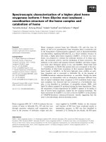
on the outlines of each condyle (red arrow) (Figure 1). A
horizontal line (black) named Horizontal Reference
Plane (HRP), joining these points, is drawn with the ruler.
The exercise will continue on the right side of the radio-
graph, for a better description of the method. The same
procedure shoud be applied to the left side, so that the
study can be completed.
The most external and posterior point of the right condyle
outline is determined. A line angled at 90° with the HRP,
tangent to the condyle and contacting this point, is drawn
with the straightedge, and the Vertical Reference Plane
(VRP), is thus obtained (black) (Figure 1). A bisector,
from the intersection of HRP and VRP, is drawn with help
of the compass. The resulting line, right line one (rL1),
projects over the ramus and part of the mandibular body.
The intersection between rL1 and the anatomical outline
of the condyle is the right condyle point (rCP), and in the
apex of the angle represents the bisector point (rBP)
(dashed black line). Cartesian lines are thus obtained, as
the geometrical principle of this study (Figure 1).
The Geometric Median Line (ML) results from drawing
the HRP mediatrix from rBP and lBP (continuous green
line), which can be more accurately done with use of a
compass. A Condilar Median Line (CML) may be traced
from rCP-lCP over the same referential horizontal plane
or over the Horizontal Line (rCp-lCp). More metrical data
can thus be produced (dashed green line). The Dental
Median Line (DML), perpendicular to the Horizontal Ref-
erence Plane (HRP), is obtained from the inferior central
interincisive point (countinuous black line) (Figure 1).
The red graphite is then used for identification and draw-
ing of the right Mental Foramen (rMF), with free identifi-
cation and marking of its central point. A line joining the
rCP and rMF points, resulting in right line 2 (rL2), is
drawn (Figure 2).
From rL2, the Median Point of the Gonial Area (rMPGo)
is drawn on the gonial region. Positioning the sharp point
of the compass on the rMF central point, an intersection
over rL2 is marked. The process is repeated from the rCP.
The compass should be opened more widely than half the
length of this line, for both drawings. The two intersec-
tions define the rL2 mediatrix. Its lower extension origi-
nates a new rMPGo on the external outline of the
mandibular angle region. In this case, only the intersec-
tion point on the mandibular border should be marked
(red) (Figure 2).
The right line 3 (rL3) and right line 4 (rL4) originate from
joining, respectively, the rMF with the rMPGo and the
rMPGo with the rCP. This results in the triangle rCP-rMF-
rMPGo, or rRBT I (right Ramus/Body Triangle I), related
to the skeletal structure. The triangle, in red, allows angu-
lar, linear measurements, such as for instance length of
the rCP-rMF line (rL2), or rCP-rMF-rMPGo angle, which
can be used in comparative studies (Figure 3).
Demarcation of the bisector of angle rC/lC and rC/VR, called (r/l)L1Figure 1
Demarcation of the bisector of angle rC/lC and rC/
VR, called (r/l)L1. The condylar point [(r/l)CP] results
from the intersection of the bisector with the anatomical
tracing of the condyle. Intersection of the bisector with the
HRP and VRP originates the bisector point (BP). The signal
(red arrow) represents the most superior and posterior
points of the external condylar surface that originate HRP
and VRP. The median line (ML) (continuous green line)
results from the mediatrix of the horizontal reference plane,
from rBP-lBP. A Condilar Median Line (CML) (dotted green
line) and a Dental Median Line (DML) (continuous black line)
are also observed.
Determination of rMGoP (arrow) from the L2 mediatrix (rCp-rMF)Figure 2
Determination of rMGoP (arrow) from the L2 medi-
atrix (rCp-rMF).
Head & Face Medicine 2009, 5:19 />Page 4 of 9
(page number not for citation purposes)
From the structural outline of the mandible, two tangent
lines can be traced (in blue) through the most dorsal
points on the posterior surface of the condyle and ramus
(rT1) and borders of the most inferior outline of the body
and the region of the mandibular angle (rT2). The bisec-
trix of rT1 and rT2 (Figure 4) determines the right Gonial
Point (rGoP) (yellow).
Another right Ramus/Body Triangle (rRBT II) can be
drawn by connecting the points rCP-rMF-rGoP-rCP,
allowing for the same angular and linear measurements
described for rRBT I, which may be traced in green. The
rRBT II is thus formed by lines L2 (red), L5 and L6 (green)
(Figure 4). A third triangle rRBT III may then originate
from linking tangents 1 and 2 (blue) with the right line 1
(rL1), representing a new opportunity for measurement.
Its limits extrapolate the mandibular tracing (Figure 4).
Similarly, the intersection of lines ML with HPR (dotted
blue lines) and rL1 (dotted black line) results in a right tri-
angle rRBT IV (Figure 4).
The potential of the proposed protocol for the definition
of tracing for dental structures may also be explored. The
crown-root structures of the lower molars are drawn with
black graphite, and the points corresponding to the widest
region of the crown (equator), in mesio-distal orientation,
are marked (red) (Figure 5a).
The sharp point of the compass is placed on the mesial
point of the first molar crown and the graphite is placed
on the distal outline of the same crown, overlaying the
tracing on this point. A semicircle is then drawn in cervical
directed to the occlusal, extending transversally to the
tooth long axis. After repositioning the sharp tip of the
compass on the distal point, and tracing the external bor-
der of the same tooth, the semicircle is repeated (Figure
5b). As a result, two intersections, one cervical and the
other occlusal, determine the long crown axis (AX) (Figure
5c). The intersection of these paired lines determines the
r Aα, r Aβ and r Aγ angles (Figure 6).
The two intersection points of the first molar crown draw-
ing are joined using the black graphite. The line is
extended to the Horizontal Plane Reference, through rL1,
and continues downwards through rL2, rL3 and rL5R,
reaching rT2. The process is repeated for the second and
third molars, for which blue and red graphite, respec-
tively, are recommended. The intersection of each of the
long crown axis, when crossing lines rC-lC (HRP), Hori-
zontal Line(HL) rL1, rL2;rL3;rL5 and rT2, originates new
The intersection of points rCP-rMP-rMGoP or lines L2-L3-L4 determines the rRBT I triangleFigure 3
The intersection of points rCP-rMP-rMGoP or lines
L2-L3-L4 determines the rRBT I triangle.
Determination of tangents (T1 and T2) (blue) and rGoP (arrow) which will give origin to Triangles rBT II (green), rBT III (blue) and rBT IV (dotted blue)Figure 4
Determination of tangents (T1 and T2) (blue) and
rGoP (arrow) which will give origin to Triangles rBT
II (green), rBT III (blue) and rBT IV (dotted blue).
Demarcation of the long axis of the dental crown (AX) of 46Figure 5
Demarcation of the long axis of the dental crown
(AX) of 46. (a) location of points on the crown equator
(red); (b) tracing with compass to position the intersection of
the lines; (c) drawing of a line segment to establish the long
axis of the dental crown.
Head & Face Medicine 2009, 5:19 />Page 5 of 9
(page number not for citation purposes)
angles which can be used for sequential measurements
(Figure 7).
An example of the image of this graphimetry, over a pan-
oramic radiograpy resulting from overlaying the images
described, shows many of the measurements which can
be applied to the inferior jaw (Figure 8). Linear measure-
ments, correlating the molars among themselves or with
MPGo, ML (pink), CML and DML among others, may be
suggested from the points marked on the dental crowns.
In sequence, different possibilities of triangle tracing are
presented. The design of a triangle l RBT V from l BP, l
MPGo and LM is stressed. A triangle RBT VI may also be
created from these points, just by replacing MPGo by GoP
(Figure 9).
Results
This graphimetric study proposes linear (vertical and hor-
izontal) and angular measurements of mandibular and
dental structures, individually, as a whole and bilaterally,
in the same radiography. It may also allow other studies,
such as comparative longitudinal measurements. The rBP
and lBP points are considered as zero degrees (0°). The
intersection between ML and the inferior border of the
chin determines 90° for both the right and the left sides.
For CML and DML, the same angular gradation is applied.
The projections of the long crown axis (AX) on the HRP or
this plane (rC-lC) on the Horizontal Line (HL) are scored
from 0 to 90 (degrees). The lines may go beyond ML, CML
and DML, particularly in case of acute angles of the third
molar, and their transfer to a parallel line (Figure 8, tooth
38 arrows) may then allow measurement. On the other
Determination of the interdental angular dimensions: αr, βr and γrFigure 6
Determination of the interdental angular dimen-
sions: αr, βr and γr. 46AX-47AX = Aαr 46AX-48AX =
Aβr 47AX-48AX = Aγr
As an example, the orientation for determination of the dif-ferent angles resulting from intersections of the long crown axis of the 46 with the HRP (0 to 90 degrees) and lines L1 L2;L3;L5 and T2 (0 to 180 degrees) is presentedFigure 7
As an example, the orientation for determination of
the different angles resulting from intersections of
the long crown axis of the 46 with the HRP (0 to 90
degrees) and lines L1 L2;L3;L5 and T2 (0 to 180
degrees) is presented. The angles are shown in orange.
Measurements extending to the mandibular dimensions are
also recorded (such as T2;L5 and 48 AX lines).
Image of panorametry traced over a panoramic radiography with information for bilateral bone-dental angular measure-ments of the mandibleFigure 8
Image of panorametry traced over a panoramic radi-
ography with information for bilateral bone-dental
angular measurements of the mandible. For clarity, the
different possibilities described in the text are not presented
(they may be seen in the preceding figures). Besides different
linear or angular measurements, the triangular areas may also
be measured and compared in terms of surface. See ade-
quacy of 48 AX (arrows) for determination of its angle with
HRP. We also point out the possibility of linear intercoronaly
measurements, such as M 38- ML (90°) and M 38- l MPGo
(pink).
Head & Face Medicine 2009, 5:19 />Page 6 of 9
(page number not for citation purposes)
hand, the angles of the different intersections (AX) can be
progressively measured on the lines that follow (L1, L2, L3
and L5 and T2). In this case, they may also be measured
from 0 degree in each side, right or left, and may reach up
to 180 degrees (Figure 7).
For linear measurement of rT1, its intersection with the
Horizontal Reference Plane and with rT2 are considered
as the farthest borders. The second tangent line, rT2, is dis-
tally limited by the rT1 intersection, whereas its mesial
border lies at the intersection with ML extension (Figure
4). In case of interest on the metric relationship with CML
or DML the procedure is repeated.
The linear measurements related to ML, CML and DML
should proceed from a right angle with the geometric ref-
erential, the median lines in this case. Internal and exter-
nal angles contained in the different triangles are
evaluated according to trigonometric patterns. All sides of
each triangle, medians and bisectors may also be meas-
ured and recorded for statistical and comparative studies.
The Aα, Aβ and Aγ angles allow a well focused study of
crown angulation among themselves.
Since dental crown landmarks are clearly visible, interden-
tal measurements may also be suggested. Image distor-
tions seem to be smaller in this area. For official recording
of the measurements, their standardization is suggested as
presented in Table 1, Table 2, Table 3, Table 4, Table 5,
Table 6, Table 7 and Table 8.
Discussion
Skull lateral teleradiographs are widely accepted for
cephalometric studies, due to the amount of information
about measurement of dental and craniofacial complexes
they provide. However, the overlaying of anatomical
structures makes the identification of marker points more
difficult and prevents comparisons between the left and
right sides [4,14]. The comparison of cephalometric and
craniometric measurement in lateral teleradiographs has
shown that the method has little reliability in the evalua-
tion of the gonial angle, with a distortion which is in aver-
age larger for the gonial angle closer to the film [5]. Even
allowing for latero-lateral studies, postero-anterior face
images in cephalostat present marker anatomical points
of difficult definition.
The method of panorametry proposed here allows the rec-
ognition, from horizontal and vertical reference planes, of
a skeletal and a dental median lines, in a mandible ana-
lyzed independent of the rigid structures of the facial skel-
eton [23]. Contrary to the proposal made by Larheim and
Svanaes (1986) [8], in our experience some asymmetry
may exist between the skeletal structure and the dental
arch without necessary classification of the Median Line
(ML) as only one. The possibility to determine a Condilar
Median Line (CML), established from the distance
between right and left Condylar Points (rCP-lCP), may
also be used for these measurements. Determination of
the Median Line from rBP-lBP follows, therefore, the Car-
tesian principle that from three coordinates - reference
horizontal and vertical planes and their bisector - the
mandibular structure can be viewed spatially. The Dental
Median Line (DML), however, is directly related to the
symmetry of the lower dental arch. These median lines
may occasionally superimpose, which could indicate a
better relation of the bone-dental symmetry.
The Mental Foramen (MF) stands out as an anatomical
point, but may be difficult to locate due to lack of uni-
formity of its border. It may be delineated, however, by
observation of the path of the nervous conduct between
the pre-molar apices, under adequate light.
We point out the measurements within the area of the man-dibular body and ramus, rRBT I (red) and rRBT II (green)Figure 9
We point out the measurements within the area of
the mandibular body and ramus, rRBT I (red) and
rRBT II (green). Triangles rRBT III (blue) l RBT IV (white)
and lRBT V (yellow) go beyond mandibular body and ramus
measurements. The common intersection point for these tri-
angles is in the BPs.
Table 1: Bone transversal linear dimensions.
Tracing Length (mm)
rBP-lBP
rCP-lCP
rMF-lMF
rMPGo-lMPGo
rGOP-lGOP
Head & Face Medicine 2009, 5:19 />Page 7 of 9
(page number not for citation purposes)
The Median Point of the Gonial Area (MPGo) in our
methodological proposal starts at line L2(r/l), and is not
meant to be defined as the angle referred to in former
studies. It is geometrically determined, and is part of the
triangular figure formed from points (r/l)CP - (r/l)MF - (r/
l)MPGo or (r/l)L2 - (r/l)L3 - (r/l)L4.
The presence of lines tangent to mandibular ramus (T1)
and body (T2) reproduces the proposal by Mattila et al.
(1977) [4] for determination of the gonial angle in ortho-
pantomograms. Subsequent studies showed that the
gonial angle is more accurate, more stable and presents
less distortions, even with variation in the position of the
patient head [4,7-11]. In our experience, the bisector of
the intersection of the tangent lines allows the determina-
tion of the Gonion Point (GoP), as a further referential
information to investigate.
Determination of the Gonion Point (GoP)allows the out-
line of a further triangle, also called Ramus/Body Triangle
II, using points (r/l)CP - (r/l)MF - (r/l)GoP). This triangle,
as with RBT I, is also contained within the limits of the
mandibular area. The RBT III triangle [(r/l)T1 - (r/l)T2 - (r/
l)L1] can associate external and internal metrics of the
mandibular body and ramus Intersection of line (r/l)ML-
L1 and the Horizontal Reference Plane originates a right
triangle, which creates through its bisector a new Carte-
sian reference near the mandibular gonial region. New tri-
angles are thus determined, from pre-existing and well
established points. Presenting its own angular and linear
dimensions, this triangle allows unilateral and bilateral
comparison to be performed, in longitudinal studies as
well. This ample graphimetric view show the mandibular
ramus and body still in triangular shape, allowing for sur-
face studies. We may suggest that, based on the presente
proposal in which the cartesian tracing evolves from the
condyles, the tracing for Condylar Morphology Scale
(CMS) and ramus height analysis mentioned by Borstlap
et al. (2004) [22], and the asymmetry indices according to
Habets et al (1988) [15] and Kjellberg et al. (1994) [17],
are reintroduced for new studies.
Using panoramic radiography, among other measure-
ments it is possible to observe molar spaces in the same
film and associate the eruptive process of third molars
Table 2: Bone unilateral linear dimensions.
Tracing* Length (mm)
rBP-ML
rBP-CML
rBP-DML
rCP-ML
rCP - CML
rCP-DML
rMPGo-ML
rMP- CMP
rMPGo-DML
rGoP - ML
rGoP-CML
rGoP -DML
rMF-ML
rMF-CML
rMF-DML
* The measurements should be obtained from a 90° angle with lines
ML, CML and DML.
Table 3: Bone linear dimensions.
Tracing Length (mm)
rCP-rMF = L2
rMF-rMPGo = L3
rMPGo-rCP = L4
rMF-rGoP = L5
rGoP-rCP = L6
rT 1
rT 2
rL1-ML (r CP -ML)
rL1-CML(r CP- CML)
rL1-DML (r CP -DML)
Table 4: Bone angular dimensions.
Angle Degrees
lBP-rBP-rMPGo
lBP-rBP-rGoP
lBP-rBP-rMF
lCP-rCP-rMPGo
lCP-rCP-rGOP
lCP-rCP-rMF
rT 1 -rT 2
rL1-ML
rL1-CML
Table 5: Angular ramus/body triangular dimensions.
Angle Degrees
rL2-rL3
rL3-rL4
rL2-rL4
rL2-rL5
rL5-rL6
rL2-rL6
rT 1-rT 2
rT 1 - rL1
rT 2-rL1
rL1-ML
ML-rBp (HPR)
ML-rBP-L1
This example is not limited to the median line, and may be repeated
with CML and ML.
Head & Face Medicine 2009, 5:19 />Page 8 of 9
(page number not for citation purposes)
with other dento-facial structures [1-
3,6,13,14,16,18,20,21,23-25].
Horizontal measurements are considered less accurate
[8,9]. Linear intercrown measurements proposed in the
present work allow the observation of possible combina-
tions of the first molar with the second and third molars,
and of these two among themselves, uni- or bilaterally. It
also allows extension of measurements for ML, CML and
DML in a 90 degree relationship Welander et al. (1989)
[9] suggested that the anterior mandibular area is more
susceptible to distortions. The present study suggests a
more reliable method, based on the establishment of a
geometric relationship of ML, CML and DML in right
angle with the Horizontal Reference Plane, where lines
rBP/lBP and rCP/lCP may also be used.
Angular measurements of the teeth performed with pano-
ramic radiography are more reliable, when compared to
other radiographic methods [3,10,12,13]. Angular distor-
tions and variability are more frequently concentrated in
the pre-molar region and canines of both arches, whereas
the molar region and the inferior borders of the mandib-
ular body and posterior border of the ramus are relatively
stable. Measurement of the gonial angle was also remark-
ably reproducible, even with largely different types of
head positioning. Angular measurements resulting from
panoramic radiographs are thus perfectly adequate for
quantitative studies, particularly of the development of
posterior dental regions and of inferior third molars [7].
In studies reported by Altonen et al. (1977) [12] and Hat-
tab et al. (1999) [20], the longitudinal axes of these teeth
were drawn through the midpoint of the occlusal surface
and bifurcation or the midpoint of the bone concentra-
tion forming this bifurcation. Catella et al. (1998) [19],
on the other hand, projected the long axis of the teeth by
a line bisecting the midpoints between the mesial and dis-
tal height of contours and the cementoenamel junction. If
the cementoenamel junction had not already formed, the
long axis was determined by a line perpendicular to the
line connecting the mesial and distal heights of contour
on the developing crown. In the search for a more geomet-
rical form, of better visual and graphic identification, we
propose drawing the long axis of the tooth based on the
crown structure. This design, however, allows the drawing
of images with deviations between the root and the crown
of the same tooth, so that the correct long axis proposed
is not adequately followed. Precision in the dental out-
lines, as provided by different methods, is one of most
important factors contributing for reliability and repro-
ducibility of graphimetric results.
We do not propose a comparison of the β angle intro-
duced by Altonen et al. (1977) [12] with the γ angle pre-
sented here, since they are obtained with different
approaches. Our concern with increasing the options of
angular measurements is based on the results of Frykholm
et al. (1977) [3]. The reliability of panoramic radiography
in providing angular measurements of adjacent teeth was
evaluated, and the authors concluded that this is the most
adequate radiographic method for the analysis of dental
angulation. The studies by Zach et al. (1969) [1] have also
prompted us to explore the possibility of using this type
of radiographic image for longitudinal investigations, fol-
lowing for instance the growth of a child and predicting
any possible impaction due to due to lack of space.
In our first methodological proposal (Puricelli, 2004)
[23], graphimetric data were enhanced, including linear
and angular measurements for comparative studies of
mandibular and dental structures. New graphic inclusions
and metric proposals are introduced in the present work.
Table 6: Intercoronary linear dimensions.
Tracing Values (mm) Tracing Values (mm)
M46-rMPGo M36-lMPGo
M46-rGoP M36-lGoP
M46-D48 M36-D38
M46-D47 M36-D37
M46-ML (90°) M36-ML (90°)
M46-CML (90°)
M46-DML(90)
M36-CML (90°)
M36-DML(90)
This table represents an example of measurements that may be
individually repeated for each tooth, from its mesial (M) and distal (D)
crown aspect. Measurements should be done at the crown equator.
Table 7: Dento-mandibular angular dimensions.
Angle Degrees
46AX-rBP/lBP (HRP)
46 AX- rCP-l CP (HL)
46AX-rL1
46AX-rL2
46AX-rL3
46AX-rL5
46AX-rT 2
The angle results from the intersection of its long axis of the dental
crown (AX) with the different lines (the procedure is repeated for all
inferior molars in both sides).
Table 8: Interdental angular dimensions.
Angle Degrees Angle Degrees
Aα 46-47 Aα 36-37
Aβ 46-48 Aβ 36-38
Aγ 47-48 Aγ 37-38
Head & Face Medicine 2009, 5:19 />Page 9 of 9
(page number not for citation purposes)
Conclusion
Considering that currently there is a lack of methodologi-
cal approaches to explore results from panoramic radiog-
raphy, this work proposes a standardizing method for the
establishment and performance of skeletal and dental
measurements of the mandible.
The reference points suggested are predominantly located
in the region between the molars and mandibular ramus,
for which image distortions are known to be smaller. The
suggested tracing method meets the needs of skeletal and
dental measurements, uni- and/or bilaterally. Measure-
ment of triangular surfaces may be explored in a future
study. The apparent excess of information generated
intends to allow maximal levels of comparison, indicating
the measurements more suitable and reliable for each sit-
uation, without the intention to exhaust all possibilities.
Statistical studies with high degree of confidence will cer-
tainly allow the indication of the most recommended
measurements. Currently, this proposal is not limited to
radiographs but contemplates also the possibility to study
panoramic CT images, particularly those obtained with
Cone Beam CT.
Skeletal abbreviations
(preceded by r or l, for right or left sides)
BP: Bisector Point; C: condyle; CML: Condilar Median
Line; CP: Condylar Point; DML: Dental Median Line;
GoA: Gonial Angle; GoP: Gonion Point; HL: Horizontal
Line; HRP: Horizontal Reference Plane; L1 to L6: lines 1 to
6; MF: Mental Foramen; ML: Median Line of the Mandi-
ble; MPGo: median point of the Gonial Area; RBT I:
Ramus/Body Triangle I; RBT II: Ramus/Body Triangle II;
RBT III: Ramus/Body Triangle III; RBT IV: Ramus/Body
Triangle IV; RBT V: Ramus/Body Triangle V; T: Tangents;
VRP: Vertical Reference Plane
Dental abbreviations
A α: alpha angle; A β: beta angle; A γ: gamma angle; AX:
Long Crown Axis
Competing interests
The author declares that they have no competing interests.
Acknowledgements
The author is indebted to Adriana Corsetti, Mário Alexandre Morganti and
Isabel Pucci.
References
1. Zach GA, Langland OE, Sippy FH: The use of the orthopantomo-
graph in longitudinal studies. Angle Orthod 1969, 39:42-50.
2. McIver FT, Brogan DR, Lyman GE: Effect of head positioning
upon the width of mandibular tooth images on panoramic
radiographs. Oral Surg Oral Med Oral Pathol 1973, 35:698-707.
3. Frykholm A, Malmgreen O, Sämfors KA, Welander U: Angular
measurements in orthopantomography. Dentomaxillofac Radiol
1977, 6:77-81.
4. Matilla K, Altonen M, Haavikko K: Determination of the gonial
angle from the orthopantomogram. Angle Orthod 1977,
47:107-110.
5. Slagsvold O, Pedersen K: Gonial angle distortion in lateral head
films: a methodologic study. Am J Orthod 1977, 71:554-564.
6. Rejebian GP: A statistical correlation of individual tooth size
distortions on the orthopantomographic radiograph. Den-
tomaxillofac Radiol 1979, 75:525-534.
7. Samawi SS, Burke PH: Angular distortion in the orthopantomo-
gram. Br J Orthod 1984, 11:100-107.
8. Larheim TA, Svanaes DB: Reproductibility of rotational pano-
ramic radiography: mandibular linear dimensions an angles.
Am J Orthod Dentofac Orthop 1986, 90:45-51.
9. Welander U, Tronge G, McDavid D: An analysis of different
planes within the image rayer in rotational panoramic radi-
ography. Dentomaxillofac Radiol 1987, 16:79-84.
10. Mckee IA, Glover KE, Willianson PC, Lam EW, Heo G, Major PW:
The effect of vertical and horizontal head positioning in pan-
oramic radiography on mesiodistal tooth angulations. Angle
Orthod 2001, 71:442-451.
11. Laster WS, Ludlow JB, Bailey LJ, Hershey HG: Accuracy of meas-
urements of mandibular anatomy and prediction of asym-
metry in panoramic radiographic images. Dentomaxillofacial
Radiol
2005, 34:343-349.
12. Altonen M, Haavikko K, Matilla K: Developmental position of
lower third molar in relation to gonial a Angle and lower sec-
ond molar. Angle Orthod 1977, 47:249-255.
13. Haavikko K, Altonen M, Mattila K: Prediction angulation devel-
opment and eruption of the third molar. Angle Orthod 1978,
48:39-48.
14. Olive R, Basford K: Reability and validity of lower third molar
space- assessment techniques. Am J Orthod 1981, 79:45-53.
15. Habets LL, Bezuur JN, Neiji M, Hansson TL: The Orthopantomo-
gram, an aid in diagnosis of temporomandibular joint prob-
lems II The vertical symmetry. J Oral Rehabil 1988, 15:465-471.
16. Ganss C, Hchban W, Kielbassa A, Umstadt TH: Prognosis of third
molar eruption. Oral Surg Oral Med Oral Pathol 1993, 76:688-693.
17. Kjellberg H: Condilar height on panoramic radiographs. A
methodologic study with a clinical application. Acta Odontol
Scand 1994, 52:43-50.
18. Ventä I, Murtomaa H, Ylipaavalniemi PA: Device to predict lower
third molar eruption. Oral Surg Oral Med Oral Pathol 1997,
84:598-603.
19. Castella P, Albright RH Jr, Straja S, Tucay OC: Prediction of man-
dibular third molar impaction in the orthodontic patient
from a panoramic radiograph. Clin Orthod Res 1998, 1:37-43.
20. Hattab FN, Alhaija ES: Radiographic evaluation of mandibular
third molar eruption space. Oral Surg Oral Med Oral Pathol 1999,
88:285-291.
21. Ventä I, Turtola L, Ylipaavalniemi P: Radiographic follow-up of
impacted third molars from age 20 to 32 years. Int J Oral Max-
illofac Surg 2001, 30:54-57.
22. Borstlap WA, Stoelinga PJ, Hoppenreijs TJ, van't Hof MA: Stabilisa-
tion of sagittal split advancement osteotomies with mini-
plates: aprospective, multicentre study with two-year
follow-up. Part I. Clinical parameters. Int J Oral Maxillofac Surg
2004, 33:433-441.
23. Puricelli E: Proposta de metodologia para traçado do maxilar
inferior em radiografia panorâmica: panorametria. Ortod
Gaúcha 2004, 8:4-10.
24. Akcam MO, Altiok T, Ozdiler E: Panoramic radiographs: a tool
for investigating skeletal pattern. Am J Orthod Dentofac Orthop
2006, 123:175-181.
25. Niedzielzska IA, Drugacz J, Kus N, Kreska J: Panoramic radio-
graphic predictors of mandibular third molar eruption. Oral
Surg Oral Med OralPathol Oral Radiol Endod 2006, 102:154-159.


![Tài liệu Báo cáo khoa học: Specific targeting of a DNA-alkylating reagent to mitochondria Synthesis and characterization of [4-((11aS)-7-methoxy-1,2,3,11a-tetrahydro-5H-pyrrolo[2,1-c][1,4]benzodiazepin-5-on-8-oxy)butyl]-triphenylphosphonium iodide doc](https://media.store123doc.com/images/document/14/br/vp/medium_vpv1392870032.jpg)