The Materials Science of Thin Films 2011 Part 5 docx
Bạn đang xem bản rút gọn của tài liệu. Xem và tải ngay bản đầy đủ của tài liệu tại đây (1.77 MB, 50 trang )
178
Chemical Vapor Deposition
B,H, mixtures generate BPSG. As noted in Section 4.6.3, LPCVD processes
have largely surpassed atmospheric CVD methods for depositing such films.
4.6.2. High-Temperature Systems
There is need to reduce semiconductor processing temperatures, but the growth
of high-quality epitaxial thin films can only be achieved by high-temperature
CVD methods. This is true of Si as well as compound semiconductors.
High-temperature atmospheric systems are also extensively employed in metallurgical coating operations. The reactors can be broadly divided into hot-wall
and cold-wall types. Hot-wall reactors are usually tubular in form, and heating
is accomplished by surrounding the reactor with resistance elements. An
example of such a reactor for the growth of single-crystal compound semiconductor films by the hydride process was given in Fig. 4-3. Higher temperatures
are maintained in the source and reaction zones ( 800-850 "C) relative to the
deposition zone (700 "C). Prior to deposition, the substrate is sometimes
-
*.....****.*
0
0
0
0
0
0
-
GAS FLOW
0
RF HEATING
o
RADIANT HEATING
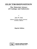
Schematic diagrams of reactors employed in epitaxial Si deposition:
(top) horizontal; (lower left) pancake; (lower right) barrel. (Reprinted with permission
from John Wiley and Sons, from S. M. Sze, Semiconductor Devices: Physics and
Technology, Copyright 0 1985, John Wiley and Sons).
Figure 4-1 3.
4.6.
CVD Processes and Systems
179
etched by raising its temperatures to 900 "C. Provision for multiple temperature zones is essential for efficient transport of matrix as well as dopant atoms.
By programming flow rates and temperatures, the composition, doping level
and layer thickness can be controlled, making it possible to grow complex
multilayer structures for device applications.
Cold-wall reactors are utilized extensively for the deposition of epitaxial Si
films. Substrates are placed in good thermal contact with Sic-coated graphite
susceptors, which can be inductively heated while the nonconductive chamber
walls are air- or water-cooled. Three popular cold-wall reactor configurations
are depicted in Fig. 4-13 (Ref. 23). Of note in both the horizontal and barrel
reactors are the tilted susceptors. This feature compensates for reactant depletion, which results in progressively thinner deposits downstream as previously
discussed. In contrast to the other types, the wafer substrates lie horizontal in
the pancake reactor. Incoming reactant gases flow radially over the substrates
where they partially mix with the product gases. Cold-wall reactors typically
operate with H, flow rates of 100-200 (standard liters per minute) and 1 vol%
of SiC1,. Silicon crystal growth rates of 0.2 to 3 pm/min are attained under
these conditions. Substantial radiant heat loss from the susceptor surface and
consumption of large quantities of gas, 60% of which is exhausted without
reacting at the substrate, limit the efficiency of these reactors.
4.6.3. Low-Pressure CVD
One of the more recent significant developments in CVD processing has been
the introduction of low-pressure reactor systems for use in the semiconductor
industry. Historically, LPCVD methods were first employed to deposit polysilicon films with greater control over stoichiometry and contamination problems.
In practice, large batches of wafers, say 100 or more, can be processed at a
time. This coupled with generally high deposition rates, improved film thickness uniformity, better step coverage, lower particle density, and fewer pinhole
defects has given LPCVD important economic advantages relative to atmospheric CVD processing in the deposition of dielectric films.
The gas pressure of
0.5 to 1 torr employed in LPCVD reactors distinguishes it from conventional CVD systems operating at 760 torr. To compensate for the low pressures, the input reactant gas concentration is correspondingly increased relative to the atmospheric reactor case. Low gas pressures
primarily enhance the mass flux of gaseous reactants and products through the
boundary layer between the laminar gas stream and substrates. According to
Eq. 4-3 1, the mass flux of the gaseous specie is directly proportional to D / 6.
-
180
Chemical Vapor Deposition
Since the diffusivity varies inversely with pressure, D is roughly lo00 times
higher in the case of LPCVD. This more than offsets the increase in 6, which
is inversely proportional to the square root of the Reynolds number. In an
LPCVD reactor, the gas flow velocity is generally a factor of 10-100 times
higher, the gas density a factor of loo0 lower, and the viscosity unchanged
relative to the atmospheric CVD case. Therefore, Re is a factor of 10 to 100
times lower, and 6 is about 3 to 10 times larger. Because the change in I)
dominates that of 6, a mass-transport enhancement of over an order of
magnitude can be expected for LPCVD. The increased mean-free path of the
gas molecules means that substrate wafers can be stacked closer together,
resulting in higher throughputs. When normalized to the same reactant partial
pressure, LPCVD film growth rates exceed those for conventional atmospheric
CVD.
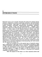
The commercial LPCVD systems commonly employ horizontal hot-wall
reactors like that shown in Fig. 4-14. These consist of cylindrical quartz tubes
heated by wire-wound elements. Large mechanical pumps as well as blower
booster pumps are required to accommodate the gas flow rates employed-e.g.,
50-500 standard cm3/min at 0.5 torr-and maintain the required operating
pressure. One significant difference between atmospheric and LPCVD systems
concerns the nature of deposition on reactor walls. Dense adherent deposits
accumulate on the hot walls of LPCVD reactors, whereas thinner, less
adherent films form on the cooler walls of the atmospheric reactors. In the
latter case, particulate detachment and incorporation in films is a problem,
especially on horizontally placed wafers. It is less of a problem for LPCVD
reactors where vertical stacking is employed. Typically, 100 wafers, 15 cm in
PRESSURE
SENSOR
SAMPLES
3 -ZONE FURNACE
/
.PUMP
-LOAD
DOOR
Figure 4-14.
Ref. 24).
\
GAS
1 NLET
Schematic diagram of hot-wall reduced pressure reactor (From
4.6.
181
CVD Processes and Systems
diameter, can be processed per hour in this reactor. In addition to polysilicon
and dielectric films, silicides and refractory metals have been deposited by
LPCVD methods.
4.6.4. Plasma-Enhanced CVD
In PECVD processing, glow discharge plasmas are sustained within chambers
where simultaneous CVD reactions occur. The reduced-pressure environment
utilized is somewhat reminiscent of LPCVD systems. Generally, the radio
frequencies employed range from about 100 kHz to 40 MHz at gas pressures
between 50 mtorr to 5 torr. Under these conditions, electron and positive-ion
densities number between lo9 and 101*/cm3, and average electron energies
range from 1 to 10 eV. This energetic discharge environment is sufficient to
decompose gas molecules into a variety of component species, such as electrons, ions, atoms, and molecules in ground and excited states, free radicals,
etc. The net effect of the interactions among these reactive molecular fragments is to cause chemical reactions to occur at much lower temperatures than
in conventional CVD reactors without benefit of plasmas. Therefore, previously unfeasible high-temperature reactions can be made to occur on temperature-sensitive substrates.
In the overwhelming majority of the research and development activity in
PECVD processing, the discharge is excited by an rf field. This is due to the
ALUMINUM
ELECTRODE
R.F
PUMP
NH3
(+*;*OR)
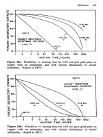
Figure 4-1 5.
Ref. 26).
Typical cylindrical, radial flow, silicon nitride deposition reactor (From
182
Chemical Vapor Deposition
fact that most of the films deposited by this method are dielectrics, and dc
discharges are not feasible. The tube or tunnel reactors employed can be
coupled inductively with a coil or capacitively with electrode plates. In both
cases, a symmetric potential develops on the walls of the reactor. High wall
potentials are avoided to minimize sputtering of wall atoms and their incorporation into growing films.
A major commercial application of PECVD processing has been to deposit
silicon nitride films in order to passivate and encapsulate completely fabricated
microelectronic devices. At this stage the latter cannot tolerate temperatures
A
much above 300 "C. parallel-plate, plasma deposition reactor of the type
shown in Fig. 4-15 is commonly used for this purpose. The reactant gases first
flow through the axis of the chamber and then radially outward across rotating
substrates that rest on one plate of an rf-coupled capacitor. This diode
configuration enables a reasonably uniform and controllable film deposition to
occur. The process is carried out at low pressures to take advantage of
enhanced mass transport, and typical deposition rates of about 300 i / m i n are
attained at power levels of 500 W. Silicon nitride is normally prepared by
reacting silane with ammonia in an argon plasma, but a nitrogen discharge with
Table 4-3. Physical and Chemical Properties of Silicon Nitride Films
NH,
from SiH,
+
properly
Density (g/cm3)
Refractive index
Dielectric constant
Dielectric breakdown
field (V/cm)
Bulk resistivity (0cm)
Stress at 23 "C on Si
(dynes/cm*)
Color transmitted
H,O permeability
Thermal stability
Si/N ratio
Etch rate, 49% HF (23 "C)
Na+ penetration
Step coverage
Si,N4
1 atm CVD
900 "C
Si3N4(H)
LPCVD
750 "C
Si,N,H,
PECVD
300 "C
2.8-3.1
2.0-2.1
2.9-3.1
2.01
6-7
6-7
2.5-2.8
2.0-2.1
6-9
10'
1015- 1017
107
6 x lo6
10'6
1015
1.5 x 10" (T)
None
Zero
Excellent
0.75
80 i / m i n
< looi
Fair
10"
Note: T = tensile; C = compressive.
Adapted from Refs. 24, 25.
0.75
(T)
1 - 8 x IO9 (C)
Yellow
Low -none
Variable > 400 'C
0.8- 1 .O
1500-3000 i / m i n
< l00i
Conformal
4.6.
183
CVD Processes and Systems
Table 4-4. PECVD Reactants and Products, Deposition Temperatures, and Rates
Deposit
a-Si
c-Si
a-Ge
c-Ge
a-B
a-P, c-P
As
Se, 'le, Sb, Bi
Mo
Ni
C (graphite)
CdS
Oxides
SiO,
GeO,
SiO,/GeO,
AI203
TiO,
T (K)
513
613
613
613
613
293-413
< 313
313
Rate (cm/sec)
10 -8-10 10-~-10-~
1 0 - 8-1010-~-10-~
10-*-1010-~
10-~-10-~
P3N5
Carbides
SIC
Tic
BXC
SiH,; SiF,-H,; Si(s)-H,
SiH,-H,; SiF,-H,; Si(s)-H,
GeH,
GeH,-H,; Ge(s)-H,
B,H,; BCI,-H,; BBr,
P(s)-H,
ASH,; As(s)-H,
Me-H
Mo(CO),
NKCO),
C(s)-H,; C(s)-N,
Cd-HzS
,
1013-1213
313-513
10-~
523
523
1213
523-113
413-613
10 -8-10 - 6
10-8-10-6
3 x 10⁻⁴
10 - 8-1010-8
Si(OC,H,),; SiH,-O,, N,O
Ge(OC,H,),; GeH,-O,, N,O
SiCI,-GeC14 + 0 ,
AIC13-0,
TiC1,-0, ; metallorganics
B(OC,H,),-O,
513-113
1213
813
523-1213
613-913
633-613
10-~-10-~
SiH,-N,, NH
AICI,-N,
GaCI,-N,
TiCI,-H, + N,
B,H6-NH3
P(s-N, ; PH 3-NZ
B2°3
Nitrides
Si3N4(H)
AN
Ga N
Ti N
BN
Reactants
413-113
613-813
673
10-~-10-~
10-8-5 x 10-6
sx
10-6
5 x 10⁻⁸-10-6
10-~-10-~
SiH,-C,H,
TiC14-CH4
BZHG-CH,
+ H,
From Ref. 27.
silane can also be used. As much as 25 at % hydrogen can be incorporated in
plasma silicon nitride, which may, therefore, be viewed as a ternary solid
solution. This should be contrasted with the stoichiometric compound Si,N, ,
formed by reacting silane and ammonia at 900 "C in an atmospheric CVD
reactor. It is instructive to further compare the physical and chemical property
differences in three types of silicon nitride, and this is done in Table 4-3.
Although Si,N, is denser, more resistant to chemical attack, and has higher
resistivity and dielectric breakdown strength, SiNH tends to provide better step
coverage.
184
Chemical Vapor Deposition
Some elements, such as carbon and boron, in addition to metals, oxides,
nitrides, and silicides, have been deposited by PECVD methods. Operating
temperatures and nominal deposition rates are included in Table 4 4 . An
important recent advance in PECVD relies on the use of microwave-also
called electron cyclotron resonance (ECR)-plasmas. As the name implies,
microwave energy is coupled to the natural resonant frequency of the plasma
electrons in the presence of a static magnetic field. The condition for energy
absorption is that the microwave frequency w , (commonly 2.45 GHz) be equal
to q B / m , where all terms were previously defined in connection with
magnetron sputtering (Section 3.7.3). Physically, plasma electrons then undergo one circular orbit during a single period of the incident microwave.
10" cm-3 in a 10-2-to-lWhereas rf plasmas contain a charge density of
torr environment, the ECR discharge is easily generated at pressures of
to
torr. Therefore, the degree of ionization is about loo0 times higher
than in the rf plasma. This coupled with low-pressure operation, controllability
of ion energy, low-plasma sheath potentials, high deposition rates, absence of
source contamination (no electrodes!), etc., has made ECR plasmas attractive
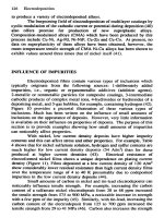
for both film deposition as well as etching processes. A reactor that has been
employed for the deposition of SO,, Al,O, , SiN, and Ta,05 films is shown
in Fig. 4-16. A significant benefit of microwave plasma processing is the
ability to produce high-quality films at low substrate temperatures.
-
MICROWAVE 2.45 GHz
MAGNET
COILS
GAS
SiHd
Figure 4-16. ECR plasma deposition reactor. (From Ref. 28, with permission from
Noyes Publications).
4.6.
185
CVD Processes and Systems
4.6.5. Laser-Enhanced CVD
Laser or, more generally, optical chemical processing involves the use of
monochromatic photons to enhance and control reactions at substrates. Two
mechanisms are involved during laser-assisted deposition, and these are illustrated in Fig. 4-17. In the pyrolytic mechanism the laser heats the substrate to
decompose gases above it and enhance rates of chemical reactions there.
Pyrolytic deposition requires substrates that melt above the temperatures
necessary for gas decomposition. Photolytic processes, on the other hand,
involve direct dissociation of molecules by energetic photons. Ultraviolet light
sources are required because many useful parent molecules (e.g., SiH, ,
Si,H, , Si,H, , N,O) require absorption of photons with wavelengths of less
than 220 nm to initiate dissociation reactions. The only practical continuouswave laser is the frequency-doubled Ar+ at 257 nm with a typical power of 20
mW. Such power levels are too low to enable high deposition rates over large
areas but are sufficient to “write” or initiate deposits where the scanned light
beam hits the substrate. Similar direct writing of materials has been accomplished by pyrolytic processes. Both methods have the potential for local
deposition of metal to repair integrated circuit chips.
A number of metals such as Al, Au, Cr, Cu, Ni, Ta, Pt, and W have been
L A S E R - ASS ISTED DEPOSl T ION
I/
PYROLYTIC
LASER
BEAM
A
SUBSTRATE
REG ION
Figure 4-1 7. Mechanisms of laser-assisted deposition. (Reproduced with permission
from Ref. 29, 0 1985 by Annual Reviews Inc.).
186
Chemical Vapor Deposition
deposited through the use of laser processing. For photolytic deposition,
organic metal dialkyl and trialkyls have yielded electrically conducting deposits. Carbonyls and hydrides have been largely employed for pyrolytic
depositions. There is frequently an admixture of pyrolytic and photolytic
deposition processes occurring simultaneously with deep UV sources. Alternatively, pyrolytic deposition is accompanied by some photodissociation of
loosely bound complexes if the light source is near the UV.
Dielectric films have also been deposited in low-pressure photosensitized
CVD processes (Ref. 30). The photosensitized reaction of silane and hydrazine
yields silicon nitride films, and SiO, films have been produced from a gas
mixture of SiH,, N,O, and N,. In SiO,, deposition rates of 150 A/rnin at
temperatures as low as 50 "C have been reported (Ref. 23), indicating the
exciting possibilities inherent in such processing.
4.6.6. Metalorganic CVD (MOCVO) (Ref. 31)
Also known as OMVPE (organometallic vapor phase epitaxy), MOCVD has
presently assumed considerable importance in the deposition of epitaxial
compound semiconductor films, Unlike the previous CVD variants, which
differ on a physical basis, MOCVD is distinguished by the chemical nature of
the precursor gases. As the name implies, metalorganic compounds like
trimethyl-gallium (TMGa), trimethyl-indium (TMIn), etc, are employed. They
are reacted with group V hydrides, and during pyrolysis the semiconductor
compound forms; e.g.,
(4-51)
Group V organic compounds TMAs, TEAS (triethyl-arsenic), TMP, TESb,
etc., also exist, so that all-organic pyrolysis reactions have been carried out.
The great advantage of using metalorganics is that they are volatile at moderately low temperatures; there are no troublesome liquid Ga or In sources in the
reactor to control for transport to the substrate. Carbon contamination of films
is a disadvantage, however. Since all constituents are in the vapor phase,
precise electronic control of gas flow rates and partial pressures is possible.
This, combined with pyrolysis reactions that are relatively insensitive to
temperature, allows for efficient and reproducible deposition. Utilizing computer-controlled gas exchange and delivery systems, epitaxial multilayer semiconductor structures with sharp interfaces have been grown in reactors such as
shown in Fig. 4-18. In addition to GaAs, other 111-V as well as 11-VI and
IV-VI compound semiconductor films have been synthesized. Table 4-5 lists
4.6.
187
CVD Processes and Systems
VACUUM
FLASK
Figure 4-1 8. Schematic diagram of a vertical atmospheric-pressure MOCVD reactor. (Reprinted with permission. From R. D . Dupuis, Science 226, 623, 1984).
Table 4-5.
Organo Metallic Precursors and Semiconductor Films
Grown by MOCVD
Vapor Pressure* of
Compound
Reactants
+ ASH,
+ NH,
+ ASH,
+ NH,
+ PH,
+ TMSb
AlAs
A1N
GaAs
GaN
GaP
GaSb
TMAl
TMAl
TMGa
TMGa
TMGa
TEGa
lnAs
InP
ZnS
ZnSe
CdS
HgCdTe
CdTe
TEIn ASH,
TEIn PH,
DEZn H,S
DEZn H,Se
DMCd H,S
Hg + DMCd + DMTe
DMCd DMTe
+
+
+
+
+
+
*log P(t0m) = (I - b / T K
Adapted from Ref. 3 1.
OM precursor
a
b
8.224
2135
8.50
1824
9.17
1.13
2532
1709
Growth Temperature
( "C)
700
1250
650-750
800
750
500-550
650-700
725
8.28
2190
7.76
7.97
1850
1865
1a8
Chemical Vapor Deposition
some films formed on insulating and semiconducting substrates together with
corresponding reactants and film growth temperatures.
Film growth rates (6) and compositions directly depend on gas partial
pressures and flow rates ( V ) . For Al,Ga, -,As films,
(4-51)
(4-52)
In these equations K ( T) is a temperature-dependent constant, and the factor of
2 enters because trimethyl-aluminum is a dimer. MOCVD has been particularly effective in depositing films for a variety of visible and long-wavelength
lasers as well as quantum well structures. The use of these precursor gases is
not only limited to semicondiictor technology; volatile organo-Y, Ba, and Cu
compounds have been explored in connection with the deposition of high-temperature superconducting films having the nominal composition YBa,Cu 307
.
4.6.7. Safety
The safe handling of gases employed in CVD systems is a concern of
paramount importance. Because the reactant or product gases are typically
toxic, flammable, pyrophoric, or corrosive, and frequently possess a combination of these attributes, they present particular hazards to humans. Exposure of
reactor hardware and associated gas-handling equipment to corrosive environments also causes significant maintenance problems and losses due to downtime. Table 4-6 lists gases commonly employed in CVD processes together
with some of their characteristics. A simple entry in the table does not
accurately reflect the nature of the gas in practice. Silane, for example, more
so than other gases employed in the semiconductor industry, has an ominous
and unpredictable nature. It is stable but pyrophoric, so it ignites on contact
with air. If it accumulates in a stagnant airspace, however, the resulting
mixture may explode upon ignition. In simulation tests of leaks, high flow
rates of silane have resulted in violent explosions. For this reason, silane
cylinders are stored outside buildings in concrete bunkers. The safety problems
are magnified in low-pressure processing where concentrated gases are used.
For example, in the deposition of polysilicon, pure silane is used during
LPCVD, whereas only 3% silane is employed in atmospheric CVD processing.
Corrosive attack of gas-handling equipment (e.g., valves, regulators, piping)
occurs in virtually all CVD systems. The problems are particularly acute in
LPCVD processing because of the damage to mechanical pumping systems.
4.6.
CVD Processes and Systems
Table 4-6.
Gas
Hazardous Gases Employed in CVD
Corrosive
Flammable
Pyrophoric
Toxic
x
x
X
Boron Trichloride
(BCl,)
Boron Trifluoride
(BF,)
Chlorine
x
a,)
Diborane
X
(BzH6)
Dichlorosilane
(SiH,CI,)
Germane
x
X
X
X
x
X
X
X
(PH3)
X
X
(SiCl,)
Stibine
(SbH 3 )
Eyeand
respiratory
irritation
Respiratory
irritation
Severe burns
(HF)
Hydrogen
(Hz)
Phosphine
(PC15)
Silane
(SiH,)
Silicon
tetrachloride
eyeand
respiratory
irritation
Anemia,
kidney damage
death
X
(GeH,)
Hydrogen chloride
(HCU
Hydrogen fluoride
Phosphorous
pentachloride
Bodily
Hazard
X
X
Respiratory
irritation,
death
190
Chemical Vapor Deposition
Since many reactors operate at high temperatures, the effluent gases are very
hot and capable of further downstream reactions in the pumping hardware.
Furthermore, the exhaust stream generally contains corrosive species such as
acids, water, oxidizers, unreacted halogenated gases, etc., in addition to large
quantities of abrasive particulates. In semiconductor processing, for example,
SiO, and Si,N, particles are most common. All of these products are ingested
by the mechanical pumps, and the chamber walls become coated with precipitates or particulate crusts. The oils used are degraded through polymerization
and incorporation of solids. The lubrication of moving parts and hardware is
thus hampered, and they tend to corrode and wear out more readily. All of this
is a small price to pay for the wonderful array of film materials that CVD has
made possible.
EXERCISES
1. a. Write a balanced chemical equation for the CVD reaction that pro-
+
+
duces A1,0, films from the gas mixture consisting of AlCl,
CO,
H,.
b. If a 2-pm-thick coating is to be deposited on a 2-cm-diameter substrate
placed within a tubular reactor 50 cm long and 5 cm in diameter,
calculate the minimum weight of AlCI, precursor required.
Repeat parts (a) and (b) for VC films from a VCl,
C,H,CH3
H,
C.
gas mixture.
+
+
2. Consider the generic reversible CVD reaction
A,
2 B, + Cg(T, > T,)
+
at 1 atm pressure (PA Pc = l), where the free energy of the reaction is
AGO = A H " - T A S " . Through consideration of the equilibria at T,
and T , ,
a. derive an expression for A PA = PA(T , ) - PA(T,) as a function of T,
A H , and A S .
b. plot A P , as a function of A H .
c. comment on the gas transport direction and magnitude as a function of
the sign and value of A H .
3. In growing epitaxial Ge films by the disproportionation reaction of Eq.
Exercises
191
4-13, the following thermodynamic data apply:
I,(,, = 21(,,
AGO = -38.4T cal/mole
Ge(s) + I,(,, = GeIq,,
AG" = - 1990 - 11.2T cal/mole
Ge(,,
a.
b.
c.
d.
+ GeI,(,,
=
2GeI,,,,
AGO = 36300 - 57.5T cal/mole
+
What is AGO for the reaction Ge(,,
21,,,, = GeI,(,,?
Suggest a reactor design. Which region is hotter; which is cooler?
Roughly estimate the operating temperature of the reactor.
Suggest how you would change the reactor conditions to deposit
polycrystalline films.
4. a. At 1200 "C the following growth rates of Si films were observed using
the indicated Si-C1-H precursor gas. The same CVD reactor was
employed for all gases.
Precursor
SiH4
SiH,Cl,
SIHCI,
SiCI,
Growth Rate (pn/min)
1
0.5
0.3
0.15
b. The density of poly-Si nuclei on an SiO, substrate at lo00 "C was
observed to be 10" cm-' for SiH,, 5 x lo7 cm-' for SiH,Cl,, and
3 x lo6 cm-' for SiHCl,.
Are the observations made in (a) and (b) consistent? From what you know
about these gases explain the two findings.
5. Plot lnP&, /Psicl,P& 1/ T K for the temperature range 800 to 1500
vs.
K, using the results of Fig. 4-5.
a. What is the physical significance of the slope of this Arrhenius plot?
b. Calculate A H for the reaction given by Eq. 4-22a, using data in
Fig. 4-4.
6. Assume you are involved in a project to deposit ZnS and CdS films for
infrared optical coatings. Thermodynamic data reveal
ZnS(,) + &(,,
+ 82.1T - 5.9T In T (cal/mole)
cq,, + %(g)
+ 85.2T - 6.64Tln T (cal/mole)
+.
+ Z"(,)
-76,400
+ Cd,,,
-50,OOO
+
1. H,S(,,
AC =
2. H,S(,,
AC =
a. Are these reactions endothermic or exothermic?
192
Chemical Vapor Deposition
b. In practice, reactions 1 and 2 are carried out at 680 "C and 600 'C,
respectively. From the vapor pressures of Zn and Cd at these temperatures, estimate the PH, P H Z ratio for each reaction, assuming equi/
s
librium conditions.
c. Recommend a reactor design to grow either ZnS or CdS, including a
method for introducing reactants and heating substrates.
7 . It is observed that when WF, gas passes over a substrate containing
exposed areas of Si and SiO, :
1. W selectively deposits over Si and not over SiO, .
2. Once a continuous film of W deposits (i.e.,
100-150 A), the
reaction is self-limiting and no more W deposits.
Suggest a possible way to subsequently produce a thicker W deposit.
-
8. The disproportionation reaction Si + SiCl, = 2SiC1, (AGO = 83,000 +
3.64T log T - 89.4T (cal/mole)) is carried out in a closed tubular
atmospheric pressure reactor whose diameter is 15 cm. Deposition of Si
occurs on a substrate maintained at 750 "C and located 25 cm away from
the source, which is heated to 900 "C. Assuming thermodynamic equilibrium prevails at source and substrate, calculate the flux of SiCl, transported to the substrate if the gas viscosity is 0.08 cP. [Hint: See problem
2.1
9. Find the stoichiometric formula for the following films:
a. PECVD silicon nitride containing 20 at% H with a Si/N ratio of 1.2.
b. LPCVD silicon nitride containing 6 at% H with a Si/N ratio of 0.8.
c. LPCVD SiO, with a density of 2.2 g/cm3, containing 3 x 10'' H
atoms/cm3.
lo. Tetrachlorosilane diluted to 0.5% mole
in H, gas flows through a
12-cm-diameter, tubular, atmospheric CVD reactor at a velocity of 20
cm/sec. Within the reactor is a flat pallet bearing Si wafers resting
horizontally. If the viscosity of the gas is 0.03 CPat 1200 "C,
a. what is the Reynolds number for the flow?
b. estimate the boundary layer thickness at a point 5 cm down the pallet.
c. If epitaxial Si films deposit at a rate of 1 pm/min, estimate the
diffusivity of Si through the boundary layer.
11. Polysilicon deposits at a rate of 30 i / r n i n at 540 "C. What deposition
rate can be expected at 625 "C if the activation energy for film deposition
is 1.65 eV?
193
References
12. Consider a long tubular CVD reactor in which one-dimensional steadystate diffusion and convection processes occur together with a homogeneous first-order chemical reaction. Assume the concentration C( x) of a
given species satisfies the ordinary differential equation
D
d2C
s -
dC
VZ
-
KC
=
0,
where K is the chemical rate constant and x is the distance along the
reactor.
a . If the boundary conditions are C(x = 0) = 1 and C(x = I mi) = 0,
derive an expression for C(x).
b. If C( s = 0) = I and d C / dx( x = 1 m) = 0. derive an expression for
C(S).
c . Calculate expressions for the concentration profiles if D = lo00
cni'isec. u = 100 cm/sec. and K = 1 sec- I . [Hint: A solution to the
differential equation is exp a x , where a is a constant.]
13. Select any film material (e.g., semiconductor. oxide, nitride. carbide
metal alloy. etc.) that has been deposited or grown by both PVD and
CVD methods. In a report. compare the resultant structures. stoichiometries. and properties. The Journal of Vacuum Science and Technology
and Thin Solid Films are good references for such information.
REFERENCES
1 . * W. Kern and V . S . Ban. in Thin Film Processes. eds. J . L. Vossen and
W . Kern. Academic Press, New York (1978).
2 . * W. Kern. in Microelectronic Materials and Processes, ed. R. A. Levy.
Kluwer Academic. Dordrecht (1989).
3.* K . K . Yee. Int. Metals Rev. 23, 19 (1978).
4.* J . W. Hastie. High Temperature Vapors - Science and Technology.
Academic Press, New York (1975).
5.* J . M . Blocher. in Deposition Technologies f o r Films and Coatings,
ed. R . F. Bunshah. Noyes. Park Ridge. NJ (1982).
6.* W. A. Bryant, J . Mat. Sci. 12. 1285 (1977).
7 . * K. K . Schuegraf. Handbook of Thin-Film Deposition Processes and
Techniques. Noyes. Park Ridge. NJ (1988).
8. J . Schlichting. Powder Metal Int. 12(3). 141 (1980).
*Recommended texts or reviews.
194
Chemical Vapor Deposition
9. E. S. Wajda, B. W. Kippenhan, and W. H. White, IBM J. Res. Dev. 7,
288 (1960).
10. T. Mizutani, M. Yoshida, A. Usui, H. Watanabe, T. Yuasa, and
I. Hayashi, Japan J. Appl. Phys. 19, L113 (1980).
11. R. A. Laudise, The Growth of Single Crystals, Prentice Hall, Englewood Cliffs, NJ (1970).
12. 0. Kubaschewski and E. L. Evans, Metallurgical Thermochemistry,
Pergamon Press, New York (1958).
13. D. R. Stull and H. Prophet, JANAF Thermochemical Tables, 2nd ed.,
U.S. GPO, Washington, DC (1971).
14. V. S. Ban and S. L. Gilbert, J. Electrochem. SOC. 122(10), 1382
(1975).
15. E. Sirtl, I. P. Hunt and D. H. Sawyer, J. Electrochem. SOC.121, 919
(1974).
16. J. E. Doherty, J. Metals 2 ( ) 6 (1976).
86,
17. T. C. Anthony, A. L. Fahrenbruch and R. H. Bube, J. Vac. Sci. Tech.
A2(3), 1296 (1984).
18. P. C. Rundle, Int. J. Electron. 24, 405 (1968).
19. A. S. Grove, Physics and Technology of Semiconductor Devices,
Wiley, New York (1967).
20. W. S. Ruska, Microelectronic Processing, McGraw-Hill, New York
(1987).
21. J. Bloem and W. A. P. Claassen, Philips Tech. Rev. 41, 60 (1983,
1984).
22. R. B. Marcus and T. T. Sheng, Transmission Electron Microscopy of
Silicon VLSl Circuits and Structures, Wiley, New York (1983).
23. S. M. Sze, Semiconductor Devices - Physics and Technology, Wiley,
New York (1985).
24. A. C. Adams, in VLSI Technology, 2nd ed.,ed. S. M. Sze, McGrawHill, New York (1988).
25. J. R. Hollahan and S. R. Rosler, in Thin Film Processes, ed. J. L.
Vossen and W. Kern, Academic Press, New York (1978).
26. M. J. Rand, J. Vuc.Sci. Tech. 16(2), 420 (1979).
27. S. Veprek, Thin Solid Films 130, 135 (1985).
28. S. Matuso in Ref. 7.
29. R. M. Osgood and H. H. Gilgen, Ann. Rev. Mater. Sci. 15, 549
(1985).
30. R. L. Abber in Ref. 7.
31. G. B. Stringfellow, Organ0 Vapor-PhaseEpitaxy: Theory and Practice, Academic Press, Boston (1989).
32. R. D. Dupuis, Science 226, 623 (1984).
= E
E %
Chapter 5
Film Formation
and Structure
5.1. INTRODUCTION
Interest in thin-film formation processes dates at least to the 1920s. During
research at the Cavendish Laboratories in England on evaporated thin films,
the concept of formation of nuclei that grew and coalesced to form the film was
advanced (Ref. 1). All phase transformations, including thin-film formation,
involve the processes of nucleation and growth. During the earliest stages of
film formation, a sufficient number of vapor atoms or molecules condense and
establish a permanent residence on the substrate. Many such film birth events
occur in this so-called nucleation stage. Although numerous high-resolution
transmission electron microscopy investigations have focused on the early
stages of film formation, it is doubtful that there is a clear demarcation
between the end of nucleation and the onset of nucleus growth. The sequence
of nucleation and growth events can be described with reference to the
micrographs of Fig. 5-1. Soon after exposure of the substrate to the incident
vapor, a uniform distribution of small but highly mobile clusters or islands is
observed. In this stage the prior nuclei incorporate impinging atoms and
subcritical clusters and grow in size while the island density rapidly saturates.
The next stage involves merging of the islands by a coalescence phenomenon
195
H 006
H OOE
E2
96 C
5.1.
Introduction
197
ISLAND
nLAYER
STRANSKI - KRASTANOV
Figure 5-2.
Basic modes of thin-film growth.
that is liquidlike in character especially at high substrate temperatures. Coalescence decreases the island density, resulting in local denuding of the substrate
where further nucleation can then occur. Crystallographic facets and orientations are frequently preserved on islands and at interfaces between initially
disoriented, coalesced particles. Coalescence continues until a connected network with unfilled channels in between develops. With further deposition, the
channels fill in and shrink, leaving isolated voids behind. Finally, even the
voids fill in completely, and the film is said to be continuous. This collective
set of events occurs during the early stages of deposition, typically accounting
for the first few hundred angstroms of film thickness.
The many observations of film formation have pointed to three basic growth
modes: (1) island (or Volmer-Weber), (2) layer (or Frank-van der Merwe),
and (3) Stranski-Krastanov, which are illustrated schematically in Fig. 5-2.
Island growth occurs when the smallest stable clusters nucleate on the substrate
and grow in three dimensions to form islands. This happens when atoms or
molecules in the deposit are more strongly bound to each other than to the
substrate. Many systems of metals on insulators, alkali halide crystals, graphite,
and mica substrates display this mode of growth.
The opposite characteristics are displayed during layer growth. Here the
extension of the smallest stable nucleus occurs overwhelmingly in two dimensions resulting in the formation of planar sheets. In this growth mode the atoms
are more strongly bound to the substrate than to each other. The first complete
monolayer is then covered with a somewhat less tightly bound second layer.
Providing the decrease in bonding energy is continuous toward the bulk crystal
value, the layer growth mode is sustained. The most important example of this
growth mode involves single-crystal epitaxial growth of semiconductor films, a
subject treated extensively in Chapter 7.
198
Film Formation and Structure
The layer plus island o r Stranski-Krastanov (S.K.) growth mechanism is an
intermediate combination of the aforementioned modes. In this case, after
forming one or more monolayers, subsequent layer growth becomes unfavorable and islands form. The transition from two- to three-dimensional growth is
not completely understood, but any factor that disturbs the monotonic decrease
in binding energy characteristic of layer growth may be the cause. For
example, due to film-substrate lattice mismatch, strain energy accumulates in
the growing film. When released, the high energy at the deposit-intermediatelayer interface may trigger island formation. This growth mode is fairly
common and has been observed in metal-metal and metal-semiconductor
systems.
At an extreme far removed from early film formation phenomena is a
regime of structural effects related to the actual grain morphology of polycrystalline films and coatings. This external grain structure together with the
internal defect, void, or porosity distributions frequently determines many of
the engineering propcrties of films. For example, columnar structures, which
interestingly develop in amorphous as well as polycrystalline films, have a
profound effect on magnetic, optical, electrical, and mechanical properties. In
this chapter we discuss how different grain and dcposit morphologies evolve as
a function of deposition variables and how some measure of structural control
can be exercised. Modification of the film structure through ion bombardment
o r laser processing both during and after deposition has been a subject of
much research interest recently and is treated in Chapters 3 and 13. Subsequent topics in this chapter are:
5.2 Capillarity Theory
5.3 Atomistic Nucleation Processes
5.4 Cluster Coalescence and Depletion
5.5 Experimental Studies of Nucleation and Growth
5.6 Grain Structure of Films and Coatings
5.7 Amorphous Thin Films
References 1-5 are recommended sources for much of the subject matter in
this chapter.
5.2. CAPILLARITY
THEORY
5.2.1. Thermodynamics
Capillarity theory possesses the mixed virtue of yielding a conceptually simple
qualitative model of film nucleation, which is, however, quantitatively inaccu-
5.2.
199
Capillarity Theory
rate. The lack of detailed atomistic assumptions gives the theory an attractive
broad generality with the power of creating useful connections between such
variables as substrate temperature, deposition rate, and critical film nucleus
size. An introduction to the thermodynamic aspects of homogeneous nucleation was given on p. 40 and is worth reviewing. In a similar spirit, we now
consider the heterogeneous nucleation of a solid film on a planar substrate.
Film-forming atoms or molecules in the vapor phase are assumed to impinge
on the substrate, creating aggregates that either tend to grow in size or
disintegrate into smaller entities through dissociation processes.
The free-energy change accompanying the formation of an aggregate of
mean dimension r is given by
AG = u3r3AGv
+ u,r2yuf + a2r2yfs- a 2 r2 T
~
~
.
(5-1)
The chemical free-energy change per unit volume, AGv,
drives the condensation reaction. According to Eq. 1-39, any level of gas-phase supersaturation
generates a negative AG, without which nucleation is impossible. There are
several interfacial tensions, y, to contend with now, and these are identified by
the subscripts f, s, and u representing film, substrate, and vapor, respectively. For the cap-shaped nucleus in Fig. 5-3,the curved surface area (u,r2),
the projected circular area on the substrate ( u2r2), and the volume ( u3r 3, are
involved, and the respective geometric constants are a, = 27r(l - cos e ) ,
u2 = T sin28, a3 = 7r(2 - 3 cos 8 cos38)/3. Consideration of the mechanical equilibrium among the interfacial tensions or forces yields Young’s equation
+
Therefore, the contact angle 8 depends only on the surface properties of the
involved materials. The three modes of film growth can be distinguished on the
DEPOSITION
DESORPTION
r
w
/
SUBSTRATE
Figure 5-3. Schematic of basic atomistic processes on substrate surface during vapor
deposition.
200
Film Formation and Structure
basis of Eq. 5-2. For island growth, 0 > 0, and therefore
Ysu
< Yfs + Y u f .
For layer growth the deposit “wets” the substrate and 6
Ysu
= Yfs
+ Yuf.
(5-3)
=
0. Therefore,
(5-4)
A special case of this condition is ideal homo- or autoepitaxy. Because the
interface between film and substrate essentially vanishes, yfs = 0. Lastly, for
S.K. growth,
Ysu
’Yf$+
Yuf.
(5-5)
In this case, the strain energy per unit area of film overgrowth is large with
respect to y U f ,
permitting nuclei to form above the layers. In contrast, a film
strain energy that is small compared with y u f is characteristic of layer growth.
Returning now to Eq. 5-1, we note that any time a new interface appears
there is an increase in surface free energy, hence the positive sign for the first
two surface terms. Similarly, the loss of the circular substrate-vapor interface
under the cap implies a reduction in system energy and a negative contribution
to AG. The critical nucleus size r* (Le., the value of r when d A G / d r = 0)
is given by differentiation, namely,
Correspondingly, AG evaluated at r = r* is
Both r* and AG* scale in the manner shown in Fig. 1-19. An aggregate
smaller in size than r* disappears by shrinking, lowering AG in the process.
Critical nuclei grow to supercritical dimensions by further addition of atoms, a
process that similarly lowers AG. In heterogeneous nucleation the accommodating substrate catalyzes vapor condensation and the energy barrier AG*
depends on the contact angle. After substitution of the geometric constants, it
is easily shown that AG* is essentially the product of two factors; Le.,
The first is the value for AG* derived for homogeneous nucleation. It is
modified by the second term, a wetting factor that has the value of zero for
0 = 0 and unity for t9 = 180”. When the film wets the substrate, there is no
5.2.
201
Capillarity Theory
barrier to nucleation. At the other extreme of dewetting, AG* is maximum and
equal to that for homogeneous nucleation.
The preceding formalism provides a generalized framework for inclusion of
other energy contributions. If, for example, the film nucleus is elastically
strained throughout because of the bonding mismatch between film and substrate, then a term a 3 r 3AG,, where AG, is the strain energy per unit volume,
would be appropriate. In the calculation for AG*, the denominator of Eq. 5-7
would then be altered to 27a:(AGv AG,)'. Because the sign of AG,, is
negative while AG,7 is positive, the overall energy barrier to nucleation
increases in such a case. If, however, deposition occurred on an initially
strained substrate-i.e., one with emergent cleavage steps or screw dislocations-then stress relieval during nucleation would be manifested by a reduction of AG*. Substrate charge and impurities similarly influence AG* by
affecting terms related to either surface and volume electrostatic, chemical,
etc., energies.
+
5.2.2. Nucleation Rate
The nucleation rate is a convenient synthesis of terms that describes how many
nuclei of critical size form on a substrate per unit time. Nuclei can grow
through direct impingement of gas phase atoms, but this is unlikely in the
earliest stages of film formation when nuclei are spaced far apart. Rather, the
rate at which critical nuclei grow depends on the rate at which adsorbed
monomers (adatoms) attach to it. In the model of Fig. 5-3, energetic vapor
atoms that impinge on the substrate may immediately desorb, but usually they
remain on the surface for a length of time r, given by
1
Edes
r, = -expv
kT
(5-9)
The vibrational frequency of the adatom on the surface is v (typically lo'*
sec-'), and Edes is the energy required to desorb it back into the vapor.
Adatoms, which have not yet thermally accommodated to the substrate,
execute random diffusive jumps and, in the course of their migration, may
form pairs with other adatoms, or attach to larger atomic clusters or nuclei.
When this happens, it is unlikely that these atoms will return to the vapor
phase. Changes in Ede5are particularly expected at substrate heterogeneities,
such as cleavage steps or ledges where the binding energy of adatoms is
greater relative to a planar surface. The proportionately large number of
atomic bonds available at these accommodating sites leads to higher Edrs
values. For this reason, a significantly higher density of nuclei is usually
202
Film Formation and Structure
obsrI-\.ed near cleavage steps and other substrate imperfections. The presence
of impurities similarly alters Edr, in a complex manner. depending on type and
distribution o f atoms or molecules involved.
We now exploit some of these microscopic notions in the capillarity theory
of the nucleation rate N. Reproducing Eq. 1-41, we obtain the expression
for N :
N =N*A*~
nuclei/cm*-sec.
(5-10)
(The Zeldovich factor, included in other treatments, is omitted here for
simplicity .) Based on the thermodynamic probability of existence, the equilibrium number of nuclei of critical size per unit area of substrate is given by
N* = n,exp - AG*/kT.
(5-1 1)
The quantity n, represents the total nucleation site density. A certain number
of these sites are occupied by adatoms whose surface density, n o , is given by
the product of the vapor impingement rate (Eq. 2-8) and the adatom lifetime,
or
no = rsPNAI-.
(5-12)
Surrounding the cap-shaped nucleus of Fig. 5-3 are adatoms poised to attach to
the circumferential belt whose area is
A* = 2xr*a,sin
e.
(5-13)
Quantities r* and 8 were defined previously, and a, is an atomic dimension.
Lastly, the impingement rate onto area A* requires adatom diffusive jumps
on the substrate with a frequency given by v exp -E,/ k T , where E, is the
activation energy for surface diffusion. The overall impingement flux is the
product of the jump frequency and n o , or
rsPNAvexp - E , / k T (cmP2sec-')
w =
vGzm
(5-14)
There is no dearth of adatoms that can diffuse to and be captured by the
existing nuclei. During their residence time, adatoms are capable of diffusing a
mean distance X from the site of incidence given by
x = JG.
(5-15)
The surface diffusion coefficient D, is essentially
D, = (1/2)agvexp - E,/kT
and therefore
X
=
a,exp
- E,
2kT
Edes
(5-16)