The Materials Science of Thin Films 2011 Part 10 pps
Bạn đang xem bản rút gọn của tài liệu. Xem và tải ngay bản đầy đủ của tài liệu tại đây (1.78 MB, 50 trang )
428
Mechanical Properties
of
Thin Films
-
m
a
W
IT
3
(I)
cn
W
cc
Z
a
0
k
cn
z
Q
E
0.1
6
a
is too simplistic a view. Sputtered films display a rich variety of effects,
including tensile-to-compressive stress transitions as a function of process
variables. For example, in rf-diode-sputtered tungsten films a stress reversal
from tension to compression was achieved in no less than three ways (Ref.
15):
CYLINDRICAL
-
POST
1""1""1""1'"'
lr
-
-
-
-
r
-
-
IIIII
0
50
100
150
200
250
a. By raising the power level about
30
W
at zero substrate bias
b.
By
reversing the dc bias from positive to negative
c. By reducing the argon pressure
Oxygen incorporation in the film favored tension, whereas argon was appar-
ently responsible for the observed compression.
The results of extensive studies by Hoffman and Thornton (Ref.
16)
on
magnetron-sputtered metal films are particularly instructive since the internal
stress correlates directly with microstructural features and physical properties.
Magnetron sputtering sources have made it possible to deposit films over a
wide range of pressures and deposition rates in the absence of plasma bom-
bardment and substrate heating. It was found that two distinct regimes,
(rn
Torr)
0.3
1
3
10
:
1
11111
I
,
I
11111
I
I
I
I
Ill
I
1
I
I
l11II
11
0.1
1
ARGON
PRESSURE
(Pa)
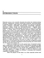
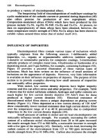
Figure
9-1
1.
(a) Biaxial internal stresses as a function
of
Ar
pressure
for
Cr,
Mo,
Ta, and
Pt
films
sputtered onto glass substrates:
0
parallel and
W
perpendicular
to
long
axis of planar cathode. (From Ref. 16).
(b)
Ar
transition pressure vs. atomic mass of
sputtered metals
for
tensile to compressive stress reversal. (From Ref. 16).
9.4.
Stress
in
Thin Films
429
separated by a relatively sharp boundary, exist where the change in film
properties is almost discontinuous. The transition boundary can be thought of
as a multidimensional space of the materials and processing variables involved.
On one side of the boundary, the films contain compressive intrinsic stresses
and entrapped gases, but exhibit near-bulklike values of electrical resistivity
and optical reflectance. This side of the boundary occurs at low sputtering
pressures, with light sputtering gases, high-mass targets, and low deposition
rates. On
the
other hand, elevated sputtering pressures, more massive sputter-
ing gases, light target metals, and oblique incidence of the depositing flux
favor the generation of films possessing tensile stresses containing lesser
amounts of entrapped gases. Internal stress as a function of the Ar pressure is
shown in Fig. 9-lla for planar magnetron-deposited Cr,
Mo,
Ta, and
Pt.
The
pressure at which the stress reversal occurs is plotted in Fig. 9-llb versus the
atomic mass of the metal.
Comparison with the zone structure of sputtered films introduced in Chapter
5
reveals that elevated working pressures are conducive to development
of
columnar grains with intercrystalline voids (zone
1).
Such a structure exhibits
high resistivity, low optical reflectivity, and tensile stresses. At lower pres-
sures the development of the zone
1
structure is suppressed. Energetic particle
bombardment, mainly by sputtered atoms, apparently induces compressive film
stress by an atomic peening mechanism.
9.4.3.
Some Theories
of
Intrinsic Stress
Over the years, many investigators have sought universal explanations for the
origin of the constrained shrinkage that is responsible for the intrinsic stress.
Buckel (Ref. 17) classified the conditions and processes conducive to internal
stress generation into the following categories, some of which have already
been discussed:
1.
Differences in the expansion coefficients of film and substrate
2.
Incorporation of atoms (e.g., residual gases) or chemical reactions
3.
Differences in the lattice spacing of monocrystalline substrates and the film
during epitaxial growth
4.
Variation
of
the interatomic spacing with the crystal size
5.
Recrystallization processes
6.
Microscopic voids and special arrangements of dislocations
7.
Phase transformations
One of the mechanisms that explains the large intrinsic tensile stresses
observed in metal films is related to item
5.
The model by Klokholm and Berry
430
Mechanical
Properties
of
Thin Films
(Ref. 11) suggests that the stress arises from the annealing and shrinkage of
disordered material buried behind the advancing surface of the growing
film.
The magnitude of the stress reflects the amount of disorder present on the
surface layer before it is covered by successive condensing layers. If the film is
assumed to grow at a steady-state rate of
G
monolayers/sec, the atoms will on
average remain on the surface for a time
G-'.
In this time interval, thermally
activated atom movements occur to improve the crystalline order (recrystalliza-
tion) of the film surface. These processes occur at
a
rate
r
described by an
Arrhenius behavior,
(9-25)
where
vu
is a vibrational frequency factor,
E, is
an appropriate activation
energy, and
T,
is
the substrate temperature. On this basis it is apparent that
high-growth stresses correspond to the condition
G
>
r,
low-growth stresses
to
the reverse case. At the transition between these two stress regimes,
G
=
r
and
E,/RT5
=
32,
if
G
is
1
sec-' and
Y,,
is taken to be
loi4
sec-'.
Experimental data in metal films generally show a steep decline in stress when
T,/Ts
=
4.5,
where
T,
is
the melting point. Therefore,
E,
=
32RTM/4.5
=
14.2TM.
In
Chapter
8
it was shown that for
FCC
metals the self-transport
activation energies are proportional to
T,
as
34TM,
25TM, 17.8T,,
and
1
3T,
for lattice, dislocation, grain-boundary, and surface diffusion mecha-
nisms, respectively. The apparent conclusion is that either surface or grain-
boundary diffusion
of
vacancies governs the temperature dependence
of
film
growth stresses by removing the structural disorder at the surface
of
film
crystallites.
Hoffman (Ref. 18) has addressed stress development due to coalescence of
isolated crystallites when forming a grain boundary. Through deposition
neighboring crystallites enlarge until a small gap exists between them. The
interatomic forces acting across this gap cause a constrained relaxation of the
top layer
of
each surface as the grain boundary forms. The relaxation is
constrained because the crystallites adhere to the substrate, and the result
of
the
deformation is manifested macroscopically as observed stress.
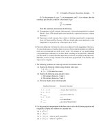
We can assume an energy
of
interaction between crystallites shown in Fig.
9-12
in much the same fashion
as
between atoms (Fig. 1-8b). At the equilib-
rium distance
a,
two surfaces
of
energy
"I,
are eliminated and replaced by a
grain boundary of energy
ygb.
For large-angle grain boundaries
-yRh
=
(1/3)-ys,
so
that the energy difference
27,
-
-ygb
=
(5/3)ys
represents
the
depth
of
the potential at
a.
As the film grows, atoms are imagined
to
individually occupy positions ranging from
r
(a hard-core radius) to
2a
(the
9.4.
Stress
in
Thin
Fllms
431
t
Z
3
ra
2a
ATOMIC
SEPARATION
Figure
9-1
2.
Grain-boundary potential. (Reprinted with permission
from
Elsevier
Sequoia,
S.A.,
from
R.
W.
Hoffman,
Thin
Solid
Films
34,
185,
1976).
nearest-neighbor separation) with equal probability. Between these positions
the system energy is lowered. If an atom occupies a place between
r
and a, it
would expand
the
film in an effort to settle in the most favored position-a.
Similarly, atoms deposited between
a
and 2a cause a film contraction.
Because the potential is asymmetric, contraction relative to the substrate
dominates leading to tensile film stresses. An estimate of the magnitude of the
stress is
EA
P
U=
-
1
-
v-d,’
(9-26)
where
d,
is the mean crystallite diameter and
P
is the packing density of the
film. The quantity
A
is the constrained relaxation length and can
be
calculated
from the interaction potential between atoms. When divided
by
ac,
A/Jc
represents an “effective” strain. In
Cr
films, for example, where E/(1
-
v)
=
3.89
x
lo”,
d,
=
130
A,
A
=
0.89
2,
and
P
=
0.96,
the film stress is
calculated to
be
2.56
x
10”
dynes/cm2. Employing this approach, Pulker and
Maser (Ref. 19) have calculated values of the tensile stress in MgF, and
compressive
stress
in
ZnS
in good agreement with measured values.
A
truly quantitative theory for film stress has yet to
be
developed, and it is
doubtful that one will emerge that is valid for different film materials and
methods of deposition. Uncertain atomic compositions, structural arrangements
and interactions in crystallites and at the film-substrate interface are not easily
amenable
to
a description in terms of macroscopic stress-strain concepts.
432
Mechanical
Properties
of
Thin
Films
9.5.
RELAXATION
EFFECTS
IN
STRESSED FILMS
Until now, we have only considered stresses arising during film formation
processes. During subsequent use, the grown-in elastic-plastic state of stress
in
the film may remain relatively unchanged with time. However, when films
are exposed to elevated temperatures
or
undergo relatively large temperature
excursions, they frequently display a number of interesting time-dependent
deformation processes characterized by the thermally activated motion of
atoms and defects. As a result, local changes in the film topography can occur
and stress levels may be reduced. In this section we explore some
of
these
phenomena that are exemplified
in
materials ranging from lead alloy films
employed in superconducting Josephson junction devices to thermally grown
SiO, films in integrated circuits.
9.5.1.
Stress Relaxation in Thermally Grown
SiO,
As
noted previously (page
395),
a volume change of some
220%
occurs when
Si
is
converted into SiO,
.
This expansion
is
constrained by the adhesion
in
the
plane of the Si wafer surface. Large intrinsic compressive stresses are,
therefore, expected to develop
in
SiO, films
in
the absence of any stress
relaxation.
A
value of
3
X
10"
dynes/cm2 has, in fact, been estimated (Ref.
20),
but such a stress level would cause mechanical fracture of both the Si and
SO,. Not only does oxidation of Si occur without catastrophic failure, but
virtually no intrinsic stress is measured
in
SiO, grown above
lo00
"C.
To
explain the paradoxical lack of stress, let us consider the viscous flow model
depicted
in
Fig.
9-13.
For
simplicity,
only
uniaxial compressive stresses are
assumed to act
on
a slab of
SiO,,
which is free to
flow
vertically.
The
SiO,
film is modeled as a viscoelastic solid whose overall mechanical response
reflects that
of
a series combination of an elastic spring and a viscous dashpot
(Fig.
13b).
Under loading, the spring instantaneously deforms elastically,
whereas the dashpot strains
in
a time-dependent viscous fashion.
If
E,
and
E~
represent the strains
in
the spring and dashpot, respectively, then the total
strain is
ET
=
E,
+
E,.
(9-27)
The same compressive stress
ax
acts
on
both the spring and dashpot
so
that
E,
=
ux/E
and
i,
=
ux/v,
where
i,
=
dE2
Id?,
and
9
is the coefficient
of
viscosity. Here we recognize that the
rate
of deformation of glassy materials,
including SO,, is directly proportional to stress. Assuming
E~
is constant,
9.5.
Relaxation
Effects
in Stressed Films
433
SiQ
FLOW
a.
k
4
tI
tI
I
si
SUBSTRATE
I
b.
C.
c7x-~-
ox
Figure
9-13.
(a) Viscous
flow
model of stress relaxation
in
SO, films. (From Ref.
20);
(b)
spring-dashpot model
for
stress relaxation;
(c)
spring-dashpot
model
for
strain
relaxation.
i,
=
-
t,
or
(l/E)dux/dt
=
-ux/7.
Upon integration, we obtain
ax
=
uoe-E'/q.
(9-28)
The initial stress in the film,
a,,
therefore relaxes by decaying exponentially
with time. With
E
=
6.6
x
10"
dynes/cm2 and
7
=
2.8
x
lo',
dynes-
sec/cm2 at
1100
"C,
the time it takes for the initial stress to decay to uo
/
e
is a
mere 4.3 sec. Oxides grown at this temperature are, therefore, expected to be
unstressed. Since
7
is thermally activated, oxides grown at lower temperatures
will generally possess intrinsic stress. The lack
of
viscous flow in a time
comparable to that of oxide growth limits stress relief in such a case.
Typically, intrinsic compressive stresses of
7
x
lo9
dynes/cm2 have been
measured in such cases.
9.5.2.
Strain Relaxation
in
Films
It
is worthwhile to note the distinction between stress and strain relaxation.
Stress relaxation in the SiO, films just described occurred at a constant total
strain or extension in much the same way that tightened bolts lose their tension
with time. Strain relaxation, on the other hand, is generally caused by a
constant load or stress and results in an irreversible time-dependent stretching
(or
contraction)
of
the material. The latter can
be
modeled by a spring and
dashpot connected in parallel combination (Fig. 13c). Under the application of
434
Mechanical Properties
of
Thin
Films
a tensile stress the spring wishes to instantaneously extend, but is restrained
from doing
so
by the viscous response of the dashpot. It is left as an exercise
for the reader to show that the strain relaxation in this case has a time
dependence given by
(9-29)
In actual materials complex admixtures of stress and strain relaxation effects
may occur simultaneously.
Film strains
can be relaxed by several possible deformation or strain
relaxation mechanisms. The rate of relaxation for each mechanism is generally
strongly dependent on the film stress and temperature, and the operative or
dominant mechanism is the one that relaxes strain the fastest. A useful way to
represent the operative regime for a given deformation mechanism is through
the use of a map first developed for bulk materials (Ref. 21), and then
extended to thin films by Murakami
e?
af.
(Ref. 22). Such a map for a
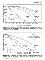
Pb-In-Au film is shown in Fig. 9-14 where the following four strain relax-
ation mechanisms are taken into account:
1.
Defectless Flow.
When the stresses are very high, slip planes can be
rigidly displaced over neighboring planes. The theoretical shear stress of
magnitude
-
11/20
is
required for such flow. Stresses in excess
of
this value
essentially cause very large strain rates. Below the theoretical shear stress limit
the plastic strain rate is zero. Defectless flow is dominant when the normalized
tensile stress
(a/p)
is greater than
-
9
x
lo-*, or above the horizontal
dotted line. This regime of flow will not normally be accessed in films.
2.
Dislocation Glide.
Under stresses sufficiently high to cause plastic
deformation, dislocation glide is the dominant mechanism in ductile materials.
Dislocation motion is impeded by the presence of obstacles such as impurity
atoms, precipitates, and other dislocations. In thin films, additional obstacles to
dislocation motion such as the native oxide, the substrate, and grain boundaries
are present. Thus, the film thickness
d
and grain size,
I,,
may be thought of
as obstacle spacings in Eq. 9-3. An empirical law for the dislocation glide
strain rate
2,
as
a
function
of
stress and temperature
is
P,
=
4,(a/ao)exp
-
AG/kT,
(9-30)
where
a,
is the flow stress at absolute zero temperature,
AG
is the free energy
required to overcome obstacles,
io
is a pre-exponential factor, and
kT
has the
usual meaning.
9.5.
Relaxation
Effects
in
Stressed
Films
435
3.
Dislocation Climb.
When the temperature is raised sufficiently, dislo-
cations can acquire
a
new degree of motional freedom. Rather than
be
impeded
by obstacles in
the
slip plane, dislocations can circumvent them by climbing
vertically and then gliding. This sequence can
be
repeated at new obstacles.
The resulting strain rate of this so-called climb controlled creep depends on
temperature and
is
given by
5
at
T
>
0.3TM;
i.,
=
A,-D,(
Pb
$)
,
kT
(9-31)
(9-32)
Here,
D,
and
DL
are the thermally activated grain-boundary and lattice
diffusion coefficients, respectively, and
A,
and A, are constants.
4.
Diffusional
Creep.
Viscous creep in polycrystalline films can occur by
diffusion of atoms within grains (Nabarro-Herring creep) or by atomic
transport through grain boundaries (Coble creep). The respective strain rates
are given by
PQ
p
n6D,
a
kT
I,d2
(L)?
k,
=
A6
(9-33)
(9-34)
where in addition to constants
A,
and
A
6,
Q
is the atomic volume and
6
is
the grain-boundary width. It is instructive to think
of
the last two equations as
variations on the theme of the Nernst-Einstein equation
(Eq.
1-35).
The
difference is that in the present context the applied stress (force) is coupled to
the resultant rate of straining (velocity). Rather than the linear coupling of
i
and
u
in diffusional creep, a stronger nonlinear dependence on stress is
observed
for
dislocation climb processes.
In constructing the deformation mechanism map, the process exhibiting the
largest strain relaxation rate is calculated at each point in the field of the
normalized stress-temperature space. The field boundaries are determined by
equating pairs
of
rate equations for
the
dominant mechanisms and solving for
the resulting stress dependence on temperature.
9.5.3.
Relaxation Effects in Metal Films during Thermal Cycling
An interesting application of strain relaxation effects is found in Josephson
superconducting tunnel-junction devices (Ref.
23)
(These are further discussed
436
Mechanical Properties
of
Thin
Films
/
DISLOCATION GLlDE
1
If
II
I
GRAINBOUNDARY
-
I
I
DIFFUSION
CREEP
I
I
a
I
I
I
-J
Ir
TVNNEL
8*RRLR
I6nd
-
I
(Pb-ln-bl
I
0
0.2
0.4
0.6
0.8
I
.o
T/TM
Figure
9-14.
Deformation mechanism map for Pb-In-Au thin
films.
(From Ref.
23).
Inset: Schematic cross section of Pb alloy Josephson junction device. (From
Ref.
22).
in
Chapter
14.)
A schematic cross section of such a device is shown
in
the inset
of
Fig.
9-14.
The mechanism of operation need not concern us, but their very
fast switching speeds (e.g.,
-
lo-''
sec) combined with low-power dissipa-
tion levels (e.g.,
-
lop6
W/device) offer the exciting potential of building
ultrahigh speed computers based on these devices. The junction basically
consists of two superconducting electrodes separated by an ultrathin 60-A-thick
tunnel barrier. Lead alloy films serve as the electrode materials primarily
because
they have a
relatively
high
superconducting transition temperature*
and are easy to deposit and pattern. The thickness of the tunnel barrier oxide is
critical and can be controlled to within one atomic layer through oxidation
of
0
*The application described here predates the explosion
of
activity in
YBa,Cu,O,
ceramic
superconductors (see Chapter
14).
9.5.
Relaxation Effects in Stressed
Films
437
Pb alloy films. Fast switching and resetting times are ensured by the low
dielectric constant of the PbO-In,O, barrier film. A serious materials-related
concern with this junction structure is the reliability of the device during
thermal cycling between room temperature and liquid helium temperature
(4.2
K)
where the device is operated. The failure
of
some devices is caused by the
rupture of the ultrathin tunnel barrier due to the mismatch in thermal expansion
between Pb alloys and the Si substrate on which the device is built. During
temperature cycling the thermal strains are relaxed by the plastic deformation
processes just considered resulting in harmful dimensional changes.
Let us now trace the mechanical history of an initially unstressed Pb film as
it is cooled to
4.2
K.
Assuming no strain relaxation, path
a
in Fig.
9-14
indicates that the grain-boundary creep field is traversed from
300
to
200
K,
followed by dislocation glide at lower temperatures. Because cooling rates are
high at
300
K,
there is insufficient thermal energy to cause diffusional creep.
Therefore, dislocation glide within film grains is expected to be the dominant
deformation mechanism on cooling. If, however, no strain relaxation occurs,
the film could then
be
rewarmed and the
a-T
path would
be
reversibly
traversed if, again, no diffusional creep occurs. Under these conditions the
film could be thermally cycled without apparent alteration of the state
of
stress
and strain. If, however, a relaxation
of
the thermal strain by dislocation glide
did occur upon cooling, then the path followed during rewarming would be
along
b.
Because the coefficient of thermal expansion for Pb exceeds that
of
Si, a large tensile stress initially develops in the film at
4.2
K.
As the
temperature is raised, dislocation glide rapidly relaxes the stress
so
that at
200
K
the tensile stress effectively vanishes. Further warming from
200
to
300
K
induces compressive film stresses. These provide the driving force to produce
micron-sized protrusions or so-called hillock or stunted whisker growths from
the film surface. This manifestation of strain relaxation is encouraged because
grain-boundary diffusional creep is operative in Pb over the subroom tempera-
ture range.
It is clear that in order to prevent the troublesome hillocks from forming, it
is necessary to strengthen the electrode film. This will minimize the dislocation
glide that originally set in motion the train of events leading to hillock
formation. Practical methods
for
strengthening bulk metals include alloying
and reducing the grain size in order to create impediments to dislocation
motion. Indeed, the alloying of Pb with In and Au caused fine intermetallic
compounds to form, which hardened the films and refined the grain size. The
result was a suppression of strain relaxation effects and the elimination
of
hillock formation.
Overall, a dramatic reduction in device failure due to
thermal cycling was realized. Nevertheless, for these and other reasons, Nb, a
438
Mechanical Properties
of
Thin Films
much harder material than Pb, has replaced the latter in Josephson junction
computer devices.
9.5.4.
Hillock
Formation
In multilayer integrated devices hillocks are detrimental because their penetra-
tion
of
insulating films can lead to electrical short circuits. Hillocks and
whiskers have been observed to sprout during electromigration (see Section 8.4
and Fig. 8-15a). Where glass films overlay interconnections, they serve to
conformally constrain the powered metal conductors. The situation is much
like a glass film vessel pressurized by
an
electromigration mass flux. Compres-
sive stresses in the conductor induced by electrotransport can be relieved by
extrusion of hillocks or whiskers, which sometimes leads to cracking of the
insulating dielectric overlayer. Interestingly, processes that reduce the com-
pression or create tensile stresses, such as current reversal during electromigra-
tion or thermal cycling, sometimes cause the hillocks to shrink in size.
From the foregoing examples it is clear that the rate of relieval of compres-
sive stress governs hillock growth. Dislocation flow mechanisms cannot gener-
ally relax stress because the intrinsic stress level present in
soft
polycrystalline
metal films is insufficient to activate dislocation sources within grains, at grain
boundaries, or at the film surface. However, diffusional creep processes can
relieve the stress. We close this section with the suggestion that diffusional
creep relaxation of the compressive stress in a film is analogous to the
outdiffusion of a supersaturated specie from a solid, e.g., outgassing of a strip.
The rate of stress change is then governed by
a+,
t)
a2+,
t)
=D
at
ax2
’
(9-35)
where compressive stress simply substitutes for excess concentration in the
diffusion equation. If, for example, a film of thickness
d
contains an initial
internal compressive stress
a(0)
and stress-free surfaces at
x
=
0
and
x
=
d,
i.e.,
a(0,
t)
=
a(d,
t)
=
0,
then
the
stress relaxes according to the equation
d2
(2n
+
1)ax
d
exp
-
(9-36)
Boundary value problems
of
this kind have been treated in the literature to
account for hillock growth kinetics, and the reader is referred to original
sources for details (Ref. 24).
9.6.
Adhesion
439
9.6.
ADHESiON
9.6.1.
Introduction
The term
adhesion
refers to
the
interaction between the closely contiguous
surfaces of adjacent bodies, Le., a film and substrate. According to the
American Society for Testing and Materials (ASTM), adhesion
is
defined as
the condition in which
two
surfaces are held together
by
valence forces or
by
mechanical anchoring or by both together. Adhesion to the substrate is
certainly the first attribute a film must possess before any of its other
properties can
be
further successfully exploited. Even though it is
of
critical
importance adhesion is one of the least understood pmperties. The lack
of a
broadly applicable method for quantitatively measuring “adhesion” makes it
virtually impossible to test any of the proposed theories for it. This state
of
affairs has persisted for years and has essentially spawned
two
attitudes with
respect to the subject (Ref.
25).
The “academic” approach is concerned with
the nature of bonding and the microscopic details of the electronic and
chemical interactions at the film- substrate interface. Clearly, a detailed under-
standing of this interface is essential to better predict the behavior of the
macrosystem, but atomistic models of the former have thus far been unsuccess-
fully extrapolated to describe the continuum behavior of the latter. For this
reason
the
“pragmatic” approach to adhesion by the thin-film technologist has
naturally evolved. The primary focus here is to view the effect of adhesion on
film quality, durability,
and environmental stability. Whereas the atomic
binding energy may
be
taken as a significant measure
of
adhesion for the
academic, the pragmatist favors the use of large-area mechanical tests to
measure
the
force or energy required to separate
the
film from the substrate.
Both approaches are, of course, valuable in dealing with this difficult subject,
and we shall adopt aspects of these contrasting viewpoints in the ensuing
discussion
of
adhesion mechanisms, measurement methods, and ways of
influencing adhesion.
9.6.2.
Energetics
of
Adhesion
From a thermodynamic standpoint the work
W,
required to separate a unit
area of
two
phases forming an interface is expressed by
W,
=
rf
+
rs
-
rfs
(9-37)
The quantities
-yf
and
T~
are
the specific surface energies of film and substrate,
and
yfs
is the interfacial energy.
A
positive
W,
denotes attraction (adhesion),
440
Mechanical Properties
of
Thin Films
and a negative
W,
implies repulsion (de-adhesion). The work
W,
is largest
when materials of high surface energy come into contact such as metals with
high melting points. Conversely,
W,
is smallest when low-surface-energy
materials such as polymers are brought into contact. When
f
and
s
are
identical, then an interfacial grain boundary forms where
y,
+
ys
>
yfs.
Under these circumstances,
y,
=
y3
and
yfs
is relatively small; e.g.,
y,s
=
(1/3)y,
in metals. If, however, a homoepitaxial film is involved, then
y,$
=
0
by definition, and
W,
=
27,.
Attempts to separate an epitaxial film from its
substrate will likely cause a
cohesion
failure through the bulk rather than an
adhesion
failure at the interface. When the film-substrate combination is
composed of different materials,
yf,
may be appreciable, thus reducing the
magnitude of
W,.
Interfacial adhesion failures tend to be more common under
such circumstances. In general, the magnitude
of
W,
increases in the order (a)
immiscible materials with different types of bonding, e.g., metal-polymer, (b)
solid-solution formers, and (c) same materials. Measured values of adhesion
will differ from intrinsic
W,
values because of contributions from chemical
interactions, interdiffusional effects, internal film stresses, interfacial impuri-
ties, imperfect contact, etc.
9.6.3.
Film
-
Substrate Interfaces
The type of interfacial region formed during deposition will depend not only on
W,
but also on
the
substrate morphology, chemical interactions, diffusion
rates and nucleation processes. At least four types of interfaces can be
distinguished, and these are depicted in Fig.
9-15.
1.
The abrupt interface is characterized by a sudden change from the film
to the substrate material within a distance of the order of the atomic spacing
(1
-5
A).
Concurrently, abrupt changes in materials properties occur due to the
lack of interaction between film and substrate atoms, and low interdiffusion
rates. In this type of interface, stresses and defects are confined to a narrow
planar region where stress gradients are high. Film adhesion in this case will
be
low because of easy interfacial fracture modes. Roughening of the substrate
surface
will tend to promote better adhesion.
2.
The compound interface is characterized by a layer
or
multilayer struc-
ture many atomic dimensions thick that is created by chemical reaction and
diffusion between film and substrate atoms. The compounds formed are
frequently brittle because
of
high stresses generated by volumetric changes
accompanying reaction. Such interfaces arise in oxygen-active metal films on
9.6.
Adhesion
441
l.0
0 0
0
0
0
2.0
0
0 0 0
0
000000
000000
000000
000000
3.
4.
00.000
.000.0
000000
0.0
0
0
0 0
o.o.ooo.o.o
o.o.o.o.o.o
o.o.o.ooo.o
.0
Figure
9-15.
Different interfacial layers
formed
between
film
and substrate:
(1)
abrupt interface;
(2)
compound interface;
(3)
diffusion interface;
(4)
mechanical anchor-
ing at interface.
oxide substrates or between intermetallic compounds and metals. Adhesion is
generally good if the interfacial layer is thin, but is poor if thicker layers
form.
3.
The diffusion interface is characterized by a gradual change in composi-
tion between film and substrate. The mutual solubility of film and substrate
precludes the formation of interfacial compounds. Differing atomic mobilities
may cause void formation due to the Kirkendall effect (Chapter
8).
This effect
tends to weaken the interface. Usually, however, interdiffusion results in good
adhesion. A related type of transition zone which can strongly promote
adhesion is the interfacial “pseudodiffusion” layer. Such layers
are
formed
when film deposition occurs under the simultaneous ion bombardment present
during sputtering or ion plating. In
this
way backscattered atoms sputtered
from the substrate efficiently mix with the incoming vapor atoms of the film to
be
deposited. The resulting condensate may
be
thought of as a metastable phase
in which the solubility of the components involved exceed equilibrium limits.
The generally high concentration of point defects and structural disorder
introduced by these processes greatly enhance “diffusion” between materials
that do not naturally mix
or
adhere.
Important examples of interdiffusion adhesion
are
to
be
found in polymer
systems that are widely used as adhesives. In view of the above, it is not
surprising that interdiffusion of polymer chains across
an
interface requires
442
Mechanical Properties
of
Thin
Films
that the adhesive and substrate be mutually soluble and that the macro-
molecules or segments be sufficiently mobile. Such conditions are easily met in
the autoadhesion of elastomers and in the solvent bonding of compatible
amorphous plastics.
4.
The mechanical interface is characterized by interlocking of the deposit-
ing material with a rough substrate surface. The adhesion strength depends
primarily on the mechanical properties of film and substrate and on the
interfacial geometry.
A
tortuous fracture path induced by rough surfaces and
mechanical anchoring leads
to
high adhesion. Mechanical interlocking is relied
upon during both electroplating and vacuum metalization of polymers.
9.6.4.
Theories of Adhesion (Ref.
25)
The adsorption theory is most generally accepted and suggests that when
sufficiently intimate contact
is
achieved at the interface between film and
substrate, the surfaces will adhere because of the painvise interaction of the
involved atoms or molecules. There is no reason to believe that the forces that
act in adhesion are any different from those that are functional within bulk
matter. Therefore, the interaction energy typically follows the behavior de-
picted in Fig. l-8b as a function of separation distance regardless of the type of
materials or surface forces involved. It is believed that the largest contribution
to the overall adhesion energy is provided by van der Waals forces (physio-
sorption). These are classified into London, Debye, and Keesom types depend-
ing, respectively, on whether neither, one, or both of the paired atoms possess
electric dipoles. Interaction energies between film and substrate atoms typically
fall off as the sixth power of the separation distance. The resulting forces are
weak and secondary bonding is said to exist with energies of
0.1
eV per atomic
pair. In addition to van der Waals forces, chemical interactions (chemisorp-
tion) also contribute to adhesion. Stronger primary covalent, ionic, and metal-
lic binding forces are involved now, and bond energies of
1
to
10
eV can be
expected.
For a typical interface containing some 10'' primary bonds/cm* at 1 eV per
bond, the total energy is
lOI5
eV/cm2 or 1600 ergs/cm2. This corresponds to
typical surface energies of metals. The bonding force can be obtained from the
bond energy
if its
variation with separation distance is known.
If,
for exampl:,
the adhesion energy drops to zero when the surfaces are parted by some
5
A,
then the specific adhesion force is
FA
=
(1600
ergs/cm2)/5
x
lo-'
cm or
3.2
x
10"
dynes/cm2. In contrast, van der Waals adhesion forces are
ex-
pected to be an order of magnitude less or roughly
lo9
dynes/cm*. Secondary
bonding forces alone may result in adequate adhesion, but the presence of
9.0.
Adhedon
443
primary bonds can considerably increase the joint strength. Surface-specific
analytical techniques such
as
laser-Raman scattering, X-ray photoelectron
spectroscopy, and
SIMS
have yielded definitive evidence that primary interfa-
cial bonding contributes significantly to the intrinsic adhesion.
Exchange of charge across Nm-substrate interfaces
also
contributes to
adhesion. As a result, electrical double layers consisting
of
oppositely charged
sheets develop and exert adhesive forces. The latter, however, are generally
small
compared with physiosorption forces. The situation is like that of a
parallel-plate capacitor. Chapman (Ref.
25)
has estimated that the attractive
force is
Q2/2cO
per unit area, where
Q
is the charge density/cm2 and
c0
is
the permittivity of
free
space. If
Q
=
10’1-1013
electronic charges/cm2 then
the resulting attractive forces are
104-108
dynes/cm2. These are small com-
pared with other force contributions to adhesion.
Theories do not always provide guidelines on how to practically achieve
good
film
adhesion in practice. Conventional wisdom, for example, suggests
using very clean substrates. This is not necessarily true for the deposition
of
metals on glass substrates because optimum adhesion appears to occur only
when the metal contacts the substrate through an oxide bond. Thus
Al
adheres
better when there is some
A1203
present between it and the glass substrate. It
is not surprising that strong oxide formers adhere well to glass. Intermediate
oxide layers can
be
produced by depositing metals with large heats of oxide
formation such as Cr, Ti,
Mo,
and Ta. Reactions of the type given by
Eq.
1-16
proceed at the interface resulting in good adhesion. Conversely, the noble
metals such
as
Au and Ag do not form oxides readily and, accordingly, adhere
poorly to glass, a fact reflected in low film stresses (Table
9-2).
To
promote
adhesion, it is common practice, therefore, to first deposit a few hundred
angstroms of an intermediate oxygen-active metal to serve as the “glue”
between the film and substrate. This is the basis of several multilayer metal-
lization contact systems such as Ti-Au, Ti-Pd-Au and Ti-Pt-Au. After
deposition of the intermediate glue layer, the second film should be deposited
without delay, for otherwise the glue metal may oxidize and impede adhesion
of
the covering metal film.
9.6.5.
Adhesion
Tests
Although there
are
no ways to directly measure interfacial atomic bond
strengths, numerous tests characterize adhesion practically. These tests have
been
recently reviewed by Steinmann and Hintermann (Ref.
26),
and Valli
(Ref.
27).
Essentially two
types
of tests are distinguished by whether tensile or
shear stresses
are
generated at the interface during testing.
F
F
i
A
ADHESIVE
TAPE
(b)
(C)
(a)
Figure
9-16.
Adhesion test methods:
(a)
pull-off test; (b) adhesive
tape
test; (c) scratch test.
(a.
and
b.
from Ref.
26,
c.
from Ref.
14).
9.6.
Adhesion
445
9.6.5.1.
Tensile-Type Tests.
The simplest of these include direct pull-off
as well as so-called topple tests and both are used primarily for coatings.
As
Fig. 9-16a indicates, force is applied to a member glued
or
soldered to the
coating, and the resultant load to cause interfacial separation is then measured.
Misalignment problems associated with normal pulling are partially overcome
by applying a torque in the topple tests. The value of
FA
is equal to
F,
the
applied force at separation divided by the contact area
A.
Acceleration tests also generate tensile stresses in the coating but without the
disadvantage of glues and mechanical linkages.
In
the ultracentrifugal method a
coated cylinder is levitated electromagnetically and spun at ever-increasing
speed until the coating debonds from the substrate.
Pulsed lasers have also been used to measure adhesion forces. When the
back of the substrate is exposed to the laser pulse, successive compressive and
tensile shock waves rapidly flex the substrate backward and then forward,
detaching the coating in the process. Adhesion is characterized by the energy
absorbed per unit area.
9.6.5.2.
Shear-Type Tests.
The adhesive
tape
test developed over a half
century ago provides the simplest and quickest qualitative measure of film or
coating adhesion. Schematically indicated in Fig. 9-16b, the test can distin-
guish between complete lifting, partial lifting, or complete adhesion with a
little bit of discrimination. The test can also be made semiquantitative by
controlling the angle of pull and the rate of pulling. With improved adhesives
the force required to peel the tape is measured as a function of angle; the force
extrapolated to zero angle is a measure of the adhesion.
In
such tests it is
necessary that the tape-film bond
be
stronger than the film-substrate bond.
9.6.5.3.
Scratch Tests.
The scratch test shown schematically in Fig. 9-16c
is a widely used means of evaluating the adhesion of films. The test consists
of
drawing a stylus or indenter
of
known radius of curvature over a film or
coating under increasing vertical loads. Resultant scratches are observed under
an optical or scanning electron microscope in order to estimate the minimum
or
critical
load
required to scribe away the film and leave
a
clear channel
or
visible substrate behind. The elastoplastic deformation is complicated, how-
ever, and films can be thinned and appear translucent while still adhering to
the substrate. Alternatively, films can remain opaque when detached. Com-
mercial equipment is available to enable the critical load to be determined on
the basis of a single scratch. This is accomplished by ramping the indenting
load between set limits, followed by visual examination of the scratch to
448
Mechanical Properties
of
Thin
Films
determine the critical load
F,
that just causes adhesion failure. The scratching
process is also accompanied by the emission of acoustic signals that are small
in magnitude when the film adheres at low loads. The onset of large acoustic
emission caused by shearing
or
fracture at the film-substrate interface has
been taken as a measure of the critical de-adhesion load, thus obviating the
need for microscopic examination. Theoretical analyses relating the critical
load, stylus geometry, and scratch dimensions to the specific adhesion force
have been made. One such relation is
FA
=
KH,Fc/~R2,
(9-38)
where the magnitude of coefficient
K
depends on the model details
(K
can
range from
0.2
to 1).
H,
is the Vickers hardness (see page 562), and
R
is the
radius of the stylus tip.
At present there is little quantitative agreement
in
FA
values obtained from
different adhesion test methods. Rather, individual tests are well suited to
internal comparisons of the same film-substrate combination prepared
in
different ways.
EXERCISES
1.
Identical metal films of equal thickness, deposited on both sides
of
a
thin
substrate strip are found to possess a residual tensile stress. One of the
films is completely removed by sputter-etching. Qualitatively describe
how the remaining film-substrate combination deforms or bows.
2.
Stress fields exists around dislocations resulting
in
matrix distortions
shown
in
Fig. 1-6.
a.
A
row of edge misfit dislocations of the same sign (orientation) lies
within a
thin
film close to and parallel
lo
the substrate interface.
Comment
on
the internal stress
in
the
film.
b. How would the film stress differ
if
the dislocations were screw type'?
c. Due to annealing, some dislocations climb vertically and some disap-
3.
It
is
desired
to
grow epitaxial films of GaSb on AlSb substrates
by
pear. How
does
this affect internal stress?
deposition at
500
"C. Refer to Table
7-1.
a. What is the expected lattice mismatch at
500
"C?
b. What thermal stress can be expected
in
the film at 20°C
if
EGaSh
=
9
I
.6
GPa and
vGaSh
=
0.3?
Exercises
447
4.
Suppose
S
=
Kd"
describes the behavior
of
the stress
(af)
x
thickness
(d)
of
a
film
as a function of
d.
(K
and
n
are constants.) Contrast the
variation of film stress and instantaneous stress versus
d.
5.
a. Consider the
strain
relaxation
of
a parallel spring-dashpot combina-
tion under constant loading and derive
Eq.
9-29.
b. The intrinsic stress in a SiO, film is
10"
dynes/cm2. If the coefficient
of
viscosity
of
SiO,
film is
q(T)
=
1.5
X
lO-*exp
EJRT
(E,
=
137
kcal/mole) over the temperature range 900-1500
"C,
how long will it
take the film to reach half
of
its final strain at 1000
"C.
Assume
E
=
6.6
X
10"
dynes/cm2, and the units
of
q
are Poise.
6.
An engineer wishes to determine whether there will be more bow at
20
"C
in a Si wafer with a 1-pm-thick SiO, film, or with a I-pm-thick Si,N,
film. Both films are deposited at
500
"C
on a 0.5 mm/'Si wafer. At the
deposition temperature the intrinsic stresses are
-
3
x
IO9
dynes/cm2 for
SiO,
and
-6
X
lo9
dynes/cm2 for Si,N,. If the respective moduli are
Es,02
=
7.3
X
IO"
dynes/cm2,
ES,,N,
=
15
X
10"
dynes/cm2, and the
thermal expansion coefficients are
asIo2
=
0.55
x
'C-I,
=
3
X
lo-'
"C-
I,
calculate the radius
of
curvature for each wafer. [Note:
Assume Poisson's ratio
for
film and substrate is
0.3.
What would the
radii of curvature be in a 15-cm-diameter wafer? What is the difference
in
height between the edge and center of the wafer?
E,,
=
16
x
10"
dynes/cm2,
a,,
=
4
x
lo-'
"C-'
.I
7.
When sequentially deposited films are all very thin compared with the
substrate, each film imposes a separate bending moment and separate
curvature. Since moments are additive,
so
are the curvatures.
a. Show that
1
1
1
1-U,
6
-+-+ +
-=
(a,d,
+
a,d2
+
+and,).
Rl
R2
R"
E,
ds2
where 1,2,.
.
.
,
n
denotes the film layer, and
a,
and
d,
the film
stress and thickness.
b.
A
5000-A-thick A1 film is deposited stress free
on
a 12.5-cm-diameter
Si
wafer
(0.5
mm thick) at
250
"C
such that there
is
no
stress
relaxation on cooling
to
20
"C.
Next, the AI-Si combination is heated
to
500
"C
where AI completely relaxes.
A
2-pm-thick Si,N, film is
then deposited with
an
intrinsic compressive stress of
700
MPa.
What
is the final radius of curvature after cooling to 20
"C?
Note the
following materials properties.
448
Mechanical Properties
of
Thin
Films
St
AI
Si,Ni,
E
(GPa)
160
66
150
a
'C-'
4
X
23
X
3
X
Assume
v
=
0.3
for
all materials.
8.
Unlike the usual thin-film-thick-substrate combination treated in this
chapter, consider thin-film multilayers. For adjacent films
1
and
2
the
corresponding film thicknesses, moduli, and unstrained lattice parameters
are
d,
,
E,
,
a,(l)
and
d,
,
E?,
a,
(2).
There is a common lattice parame-
ter,
Zo,
at the interface between films.
a. What is the strain in each film?
b. What are the corresponding stresses?
c. If the forces are equilibrated, show that
9.
In
Fig. 14-17 the structure
of
the (250
A)
Si-(75
A)
Geo,,Sio,6 superlattice
is shown. The
[loo]
moduli for Ge and Si are
E,,
=
141 GPa,
ESi
=
181
GPa and a,(Ge)
=
5.66
A,
a,(Si)
=
5.43
A
are the corresponding lattice
parameters. If the properties of Ge,,Si,, are assumed to be derived from
weighted composition averages
of
pure component properties, find
a. the common interfacial (in-plane) lattice parameter using the results of
b. the strains and stresses in the
Si
and Ge,,Si,,, layers.
c. the
strained
lattice parameters
noma1
to the film layers.
Assume Poisson's ratio is 0.37.
the previous problem.
10.
Consider a substrate of thickness
d,
containing deposited films
of
thick-
ness
d,
on either side that are uniformly stressed in tension to a level
of
uf.
The substrate
is
assumed
to
be uniformly compressed. Film and
substrate have the same elastic constants.
a. Determine the substrate stress, assuming force equilibrium prevails.
b.
Show that under the foregoing conditions the net moment with respect
to an axis at the center of the substrate vanishes.
c. One film is totally annealed
so
that its stress vanishes. The substrate
and other
film
are unaffected in the process. What
is
the net force
imbalance or resultant force? What is the net moment imbalance
or
resultant moment?
References
449
d. In the absence of external constraints the film-substrate will elastically
deform to find a new equilibrium stress distribution with zero resultant
force and moment. A uniform force as well as a moment (arising from
a linear force distribution through the film-substrate cross section) are
required
to
counter the mechanical imbalance of part (c). What is the
stress contribution
to
the remaining film from the uniform force? What
is the maximum stress contribution to the remaining film from the
moment?
e.
What is the
new
maximum stress in the remaining film and what sign
is it?
1 1.
Voids and porosity are sometimes observed in abrupt, compound, diffu-
sion, and mechanical interfaces between films and substrates. Distinguish
the sources of these defects at these interfaces. Which interfaces are likely
to contain microcracks? Why?
REFERENCES
1.
G. Gore,
Trans. Roy.
SOC.
(London),
Part
1, 185 (1858).
2.
D. P. Seraphim,
R.
Lasky, and C.
Y.
Li, eds.
Principles
of
Electronic
Packaging,
McGraw-Hill, New York
(1989).
3.*
R.
W. Hoffman, in
Physics
of
Thin Films,
Vol.
3,
eds. G. Hass and
R.
E.
Thun, Academic Press, New
York
(1966).
4.
C. A. Neugebauer,
J.
Appl. Phys.
32,
1096 (1960).
5.
L.
E. Trimble and G.
K.
Celler,
J.
Vac. Sci. Tech.
B7,
1675 (1989).
6.
W. C. Oliver,
MRS
Bull.
XII(5),
15 (1986).
7.*
W.
D.
Nix,
Met. Trans.
20A,
2217 (1989).
8.
G.
G.
Stoney,
Proc.
Roy. Soc. London
A82,
172 (1909).
9.
E. Suhir and Y C. Lee, in
Handbook
of
Electronic Materials,
Vol.
1,
ed. C.
A.
Dostal,
ASM International, Metals Park, Ohio
(1989).
lo.*
D.
S.
Campbell, in
Handbook
of
Thin Film Technology,
eds.
L.
I.
Maissel and
R.
Glang, McGraw-Hill, New
York
(1970).
11.
E.
Klokholm
and B.
S.
Berry,
J.
Electrochem.
SOC.
115,
823 (1968).
12.
R.
E.
Cuthrell, D. M. Mattox, C.
R.
Peeples, P.
L.
Dreike, and
K.
P.
Lamppa,
J.
Vac. Sci. Tech.
A6(5),
2914 (1988).
13.
A.
E.
Ennos,
Appl. Opt.
5,
51 (1966).
*Recommended texts or reviews.
450
Mechanical Properties
of
Thin
Films
14.*
H. K. Pulker, Coatings
on
Glass, Elsevier, Amsterdam
(1984).
15.
R.
W.
Wagner, A. K. Sinha, T. T. Sheng,
H.
J.
Levinstein, and
F.
B.
Alexander,
J.
Vac.
Sci.
Tech.
11,
582 (1974).
16.
D.
W. Hoffman and
J.
A.
Thornton,
J.
Vac. Sci. Tech.
20,
355 (1982).
17.
W.
Buckel,
J.
Vac. Sci. Tech.
6,
606 (1969).
18.
R.
W.
Hoffman, Thin Solid Films
34,
185 (1976).
19.
H.
K. Pulker and
J.
Maser, Thin Solid Films
59,
65 (1979).
20.
E.
A. Irene, E. Tierney, and
J.
Angilello,
J.
Electrochem.
SOC.
129,
2594 (1982).
21.
M.
F.
Ashby, Acta Met.
20,
887 (1972).
22.*
M.
Murakami, T.
S.
Kuan, and
I.
A. Blech, Treatise
on
Materials
Science and Technology,
Vol.
24,
eds.
K.
N.
Tu and R. Rosenberg,
Academic Press, New York
(1982).
23.
C.
J.
Kircher and
M.
Murakami, Science
208
944 (1980).
24.
P. Chaudhari,
J.
Appl. Phys.
45,
4339 (1974).
25.*
B.
N.
Chapman,
J.
Vac. Sci. Tech.
11,
106 (1974).
26.
P. A. Steinmann and
H.
E. Hintermann,
J.
Vac.
Sci.
Tech.
A7,
2267
(1989).
27.
J.
Valli,
J.
Vac.
Sci.
Tech.
A4,
3007 (1986).
hapter
1
I
Electrical and Magnetic
Properties
of
Thin Films
10.1.
INTRODUCTION TO
ELECTRICAL
PROPERTIES
OF
THIN
FILMS
10.1
.l.
General Considerations
Electrical properties of thin films have long been
of
practical importance and
theoretical interest. The solid-state revolution has created important new roles
for thin film electrical conductors, insulators, and devices. What was once
accomplished with large discrete electrical components and systems is now
more efficiently and reliably achieved with microscopic thin-film-based inte-
grated circuit chips. Regardless of the class of material involved, its physical
state
or
whether it is in bulk or film form, an electric current of density
J
(amps/cm2) is said to flow when a concentration of carriers
n
(number/cm3)
with charge
q
moves with velocity
u
(cm/sec) past a given reference plane in
response to an applied electric field
E
(V/cm). The magnitude of the current
flow
is expressed by the simple relation
For
most materials, especially at small electric fields the carrier velocity is
proportional to
E
so
that
J=
nqu.
(10-1)
u
=
pG.
(10-2)
451
452
Electrical end Magnetlc
Properties
of
Thin Films
The proportionality constant or velocity
per
unit field is known
as
the mobility
p.
Therefore,
J
=
nqp8,
(10-3)
and by
Ohm’s
law
(J
=
u8)
the conductivity
u
or reciprocal of the resistivity
p
is given by
u
=
I/p
=
nqp.
(10-4)
Quantitative theories of electrical conductivity seek to define the nature,
magnitude, and attributes of the material constants in these equations. Corol-
lary questions revolve about how
n
and
u
or
p
vary as a function
of
temperature, composition, defect structure, and electric field. An alternative
complementary approach to understanding the response of materials to elec-
trical fields involves electronic band structure considerations that, as noted in
Chapter
1,
have successfully modeled property differences. Comprehensive
descriptions of conduction integrate what might be termed the “charge carrier
dynamics” approach with the band structure viewpoint. The former is more
intuitive and will be adopted here for the most part, but resort will also be
made
to
band diagrams and concepts.
This chapter focuses primarily on the electrical conduction properties of thin
metal, insulating, and superconducting films. Almost half of the classic
Handbook of Thin Film
Technology,
edited by Maissel and Glang, is
devoted to a treatment of electrical and magnetic properties of thin films.
Though dated, this handbook remains a useful general reference for this
chapter. Much of what is already known about bulk conduction provides a
good basis for understanding thin-film behavior. But there are important
differences that give thin films unique characteristics and these are enumerated
here:
1.
Size effects or phenomena that arise because
of
the physically small
dimensions involved-
Examples include surface scattering and quantum
mechanical tunneling of charge carriers.
2.
Method of film preparation-It
cannot
be
sufficiently stressed that the
electrical properties of metal and insulator films are a function of the way
they are deposited or grown. Depending on conditions employed, varying
degrees
of
crystal perfection, structural and electronic defect concentra-
tions, dislocation densities, void or porosity content, density, grain mor-
phology, chemical composition and stoichiometry, electron trap densities,
eventual contact reactions, etc., result with dramatic property implications.
Insulators (e.g., oxides, nitrides) are particularly prone to these effects and
metals are less affected.