The Materials Science of Thin Films 2011 Part 12 pptx
Bạn đang xem bản rút gọn của tài liệu. Xem và tải ngay bản đầy đủ của tài liệu tại đây (1.91 MB, 50 trang )
528
Optical Properties
of
Thin
Films
nonabsorbing substrate is
n2
=
1.5, the value for plate glass. The oscillatory
nature of the reflected light intensity, caused by interference effects, has a
periodicity related to the film thickness and index of refraction. This is
the
basis for experimentally determining the thickness of transparent films if the
index of refraction is known
(see
Chapter
6).
Conversely, the optical proper-
ties of the film can
be
determined at a particular wavelength if its thickness is
known. Maxima
or
minima
in
the
reflected intensity occur at specific fdm
thicknesses, for given wavelengths, depending on whether the refractive index
of the film is greater
or
less than that of the substrate. In the former case the
reflectivity is enhanced, whereas in the latter case reflectivity
is
diminished.
Optimization of these two effects has led to the development
of
dielectric
mirrors and antireflection coatings, respectively.
To
quantify the issues related to antireflectivity, Eq. 11-17 reveals that
r
vanishes when
rl
+
r,exp
-
is
=
0
or when the denominator goes to infinity.
The latter is an impossibility, since
rl
and
r2
are less than or equal to 1. The
remaining condition can be decomposed into two real transcendental equations:
(a)
r,
+
r2cos
6
=
0
and
(b)
r,sin
6
=
0.
Equation
@)
implies that
6
=
0,
f
a,
+2a,
f
3n,
etc., but the simultaneous satisfaction of equation
(a)
requires the selection of
6
=
f
a,
&
3n,
f
5a, etc. Under these conditions,
r,
-
r2
=
0
or
(no
-
n,)/(n,
+
n,)
=
(n,
-
n,)/(n,
+
n2).
Therefore,
n,=
Jnonz.
(1
1-20)
Since
6
=
4nn,d,/X
=
a,
3a,
5~, etc,
x
3x
5x
n,d=
-
-
-
,
etc.
4’
4’4
(1
1-21)
Equations 11-20 and 11-21 represent the amplitude and phase conditions for
zero reflectance, respectively. In the design of a one-layer antireflection
coating, the film index
of
refraction should be the geometric mean of the
refractive indices of adjacent media. This is only strictly
true
for the wave-
length
X
for
which
the
optical thickness of the film is X/4,
3h/4,
etc.
=
1.23 is
optimal for antireflection purposes. Clearly, this is only one consideration
among
many,
including availability,
ease
of deposition, hardness, and
environ-
mental stability, which must
be
taken into account when choosing the film
layer. The most widely used
AR
coating is a X/4-thick film of MgF, with
n,
=
1.38.
It
can
be
used
to coat either glass
or
acrylic substrates. In the
absence of an
AR
coating, glass will exhibit a reflectance of ((1.0
-
1.52)/(1.0
+
1.52))2
=
0.043. Suppose it is desired to reduce the reflectance
at a wavelength of 5500
A.
Then the film thickness required is X/4n1 or
To coat a glass lens
(n2
=
1.52), a film with
n,
=
11
-3
Thin-Film
Optics
529
Figure
tics.
(b)
WAVELENGTH
(nm)
(a)
5
h
E4
2
52
Cl
w
0
23
0
U
w
11111111111111/1111
500
600
700
'
'
I
WAVELENGTH
(nm)
(W
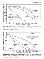
11-1
0.
(a)
Single
(S)
and
double
(0)
layer antireflection coating
Broadband antireflection
coating
characteristics.
(From
Ref.
5).
characteris-
5500/4(1.38)
=
996
A.
Under these conditions the reflectance
is
given by
Eq.
11-18
with
r,
=
(1.0
-
1.38)/(1.0
+
1.38)
=
-0.160,
r,
=
(1.38
-
1.52)/(1.38
+
1.52)
=
-0.0483,
and
6
=
a.
Substitution in
Eq.
11-18
yields
a value
of
R
=
0.0126,
indicating
an
almost
fourfold decrease
in
reflectivity.
Greater
improvements occur
for
higher
n2
values
of
the underlying substrate.
As
an example, for an uncoated glass with
n,
=
1.75
the reflectance is
0.074.
With a quarter-wave-thick MgF, coating,
R
is reduced to
0.0025.
At
other
wavelengths, but
the
same
optical
thickness,
R
will
be
different because
n,
varies with
X
(Le.,
dispersion) and
because
of
changes in
6.
The reflectance
reduction
with a single-layer
AR
coating
as
a
function
of wavelength is shown
in Fig.
11-10.
530
Optical Properties
of
Thin Films
It is instructive to end the discussion with several observations made by
Anders. (Ref.
3)
1.
There is a more rapid variation of
6
and hence
R
with
A
for a
3x14
film
than for a
X/4
film. Therefore,
R
will
be
less dependent on wavelength
with a
X/4
coating.
2.
It
is
not always true that films of high refractive index give a high
reflectance, whereas those with low refractive index yield AR coatings. The
rule is that if the reflected amplitudes
rl
and
r2
are of the same sign,
antireflection behavior is observed; if they
are
of opposite sign, then
reflection from the surface is enhanced.
3.
For very large amplitude values
of
f,
=
-
r2,
R
approaches
100%
and the
reflection becomes zero only in narrow wavelength bands at
X/2,
X,
3X/2,
.
. . .
This
occurs physically when a film is sandwiched between two
media of the same refractive index, Le., cemented film
(n,
In,
/n2),
as
shown in Fig.
11-9.
11.3.3.
Absorbing Films
The mechanisms by which materials absorb radiation were treated earlier.
Absorption effects can
be
formally incorporated into the Fresnel equations by
replacing the refractive index
n
by the complex refractive index; i.e.,
N
=
n
-
ik.
For the case of reflection due to normal incidence of light at an interface
between nonabsorbing and absorbing media of refractive indices
no
and
n,
-
ik,
,
respectively,
no
-
n,
+
ik,
rl
=
no
+
n,
-
ik,
(1
1-22)
By evaluating
I
r,
I
,,
we have the reflectance formula Eq.
11-6.
As an example, consider the reflectance of
Al
front surface mirrors pro-
duced some
15
years apart. Hass (Ref.
15)
measured the optical constants of
Alto be
NA,
=
0.76
-
i5.5
in
1946
and
PIA,
=
0.81
-
i5.99
in
1961.
Substi-
tution in
Eq.
11-6
with
no
=
1
yields respective reflectances of
0.909
and
0.9
16.
Improved deposition technology including higher and cleaner vacua,
purer metal, and higher evaporation rates were probably the cause of the
enhanced reflectance. An
R
value of
0.91
could
be
achieved with a hypotheti-
cal
absorption-free material with
n
=
43.
This extremely high value can
be
thought of as the effective refractive index for aluminum.
A frequently asked question regarding thin
fdms
is,
how thick must
a
metal
film (on a transparent substrate)
be
before it is continuous? By this is meant the
11.4
Multilayer Optical Film Applicatlons
531
thickness at which it can no longer be seen through. A simple estimate can be
obtained by arbitrarily assuming that a drop in transmitted intensity by a factor
of 1
/e
occurs when the film is continuous. Therefore, the use of Eq. 11-3 with
I/Zo
=
1
/e
yields
4
a
kd
/
X
=
1, or
d
=
X/4
a
k.
It is clear that the answer to
the question not only depends on the type of metal but also on the wavelength
of light used to view it. The critical thickness for A1 films at
5500
is 82
A,
whereas for Au films it is 185
A.
It is common experience, however, that films
that are considerably thicker exhibit some transparency. The reason is that
ultrathin films condense in an island structure of discrete clusters rather than
as
planar, continuous, homogeneous layers assumed in the optical theory. An
alternative approach to this problem, which is left to the reader as a lengthy but
healthy exercise in the use of complex numbers, is to consider the optical
structure
no
/n,
-
ik,
/n2
corresponding to free-space/metal film/substrate.
From
Eq.
11-19,
T
can be calculated for different film thicknesses.
By inverting the order of the last two optical components, Le.,
no
/nl
/n2
-
ik,,
we have the case
of
the back surface or protected mirror.
It
is
commonly believed that the reflection properties of the mirror are unaffected
by the protective layer. In reality, the latter actually reduces the reflectance in
the visible, and, particularly, in the
UV
and
IR
ranges.
The remaining case,
no
/n,
-
ik,
/n2
-
ik,,
models the optical behavior
of
an
absorbing film on an absorbing substrate. This structure was recently
used
to
determine the real-time kinetics
of
regrowth of epitaxial Si into an
amorphous Si (surface) layer. By bouncing a He-Ne laser
beam
off
the surface
and monitoring the reflected beam intensity, the instantaneous position of the
epitaxial
-
amorphous interface could be unfolded from the attenuated periodic
signal (Ref. 16). Such a measurement is possible because the optical constants
of crystalline and amorphous Si differ. (See Problem
9,
p.
543.)
11.4.
MULTILAYER OPTICAL FILM
APPLICATIONS
11.4.1.
Introduction
Once
the
basic principles governing the applications
of
single
dielectric
films
and their deposition methods were firmly established, extension to multilayer
systems was naturally driven by several factors (Ref.
17):
1.
By
suitable variations in design, it is possible to obtain improved AR
2.
Systems
with
a vast variety of optical filtering properties can be achieved
properties over a broader spectral range.
532
Optical
Properties
of
Thin
Films
ANTI-REFLECTION
HIGH-REFLECTIONS
BEAMSPLllTERS
h h h
OR
DICHROIC FILTER
DICHROIC
h
h
1
'riii
'1
)==@FZING
FILTER BEAMSPLllTER
h
h
h
Figure
11-11.
Typical
applications
of
thin
films and
film
systems
in optics.
(From
Ref.
5).
usually with the use
of
many film layers (sometimes a dozen
or
more) but
with only a very limited number
of
materials (e.g., MgF,
and
ZnS).
3.
Multilayer optical filters have advantages over other
types
of
filters. The
reason is that there
is
very little absorption loss in dielectric film layers,
since they rely on the effects
of
interference.
4.
The principles
of
design
of
optical systems applicable
to
one region
of
the
electromagnetic spectrum (e.g., visible) are also valid in other regions
(e.g.,
UV
and
IR).
Various types
of
thin-film optical component characteristics are shown in
Fig
11-11
where the desired reflectance and transmittance properties are
schematically indicated as a function
of
wavelength.
11.4.2.
AR
Coatings
Antireflection coatings constitute
the
overwhelming
majority
of
all optical
coatings produced. They are used on the lenses
of
virtually all optical
equipment, including cameras, microscopes, binoculars, range finders, tele-
scopes, and on opthalmic glasses. Because
of
the reflection at each air-glass
interface, intolerably large light losses can rapidly mount in complex lens
11.4
Multilayer Optical Film Applications
533
systems. Neglecting absorption effects, the transmission of an optical system
is
given by
T
=
(1
-
Rl)(l
-
R2)(1
-
R3).
. .
,
(1
1-23)
where the Ri
are
the reflectances
(Eq.
11-5)
at the individual optical inter-
faces. For example, in a system with uncoated lenses consisting
of
20
interfaces, each with R
=
0.05,
the value
of
T
=
(0.95)20
=
0.358.
If,
how-
ever, R is reduced to
0.01
by means
of
AR
coatings, then
T
=
0.818. The
measured transmission
is
actually somewhat higher than these estimates be-
cause light is backreflected at internal air-glass interfaces. The improvement
is
impressive indeed. In addition to enhancing light transmission,
AR
coatings
reduce glare. The
so-called
veiling glare causes a reduction in image contrast
by illuminating regions of the image that should normally be
dark.
Lastly,
since lens surfaces fortuitously act as
mirrors
in addition to refractors, spurious
ghost images are frequently generated. These are also reduced through the use
of
AR
coatings. Other optical systems that derive benefit from the use of such
coatings to maximize the capture of light include solar cells, infrared detectors,
and magneto-optical devices.
In the case of the double-layer coating where the indices of refraction vary
successively as no
(=
l)/n, /n2 /n3 from free space to the substrate, the
complex reflectivity amplitude is given by
rl
+
r2e-iSl
+
r3ei(h+h)
+
r
r r
e-ihz
1
+
rlr2e-'4
+
r
r
e-i(4+*d
+
r
r
e-%
(
1 1-24)
by analogy with
Eq.
11-17.
For
normal incidence the indicated
r
for each
of
the three interfaces is given by
123
r=
13
23
ni-,
-
n, 47rn,d1 4?rn2d2
,
a,=-
A'
r.
=
and
6,
=
-*
'
ni-l
+
ni
A
where
d,
and
d2
are the thicknesses
of
the coating layers. Zero reflectance at
one wavelength will obtain when the condition n2
=
n, &/no is fulfilled.
Once film n, has been selected, this condition serves to specify the optimal
value of
n,.
The improvement
of
a double-layer
AR
coating relative to the
single-film coating is shown
in
Fig. 11-loa. Interestingly, although the double
layer results in a considerable reflectance reduction at wavelengths centered
about
5500
A,
the response is worse at the spectral extremes due to the high
curvature of the R vs.
A
dependence. Greater care is required in controlling
the film thickness in bilayer coatings than in single layers. In the latter a film
thickness error simply means that the reflectance minimum is shifted to another
wavelength.
In
contrast, an error in double-layer thicknesses can not only
534
Optical
Properties of
Thin
Films
eliminate reflection minima but even increase reflectance. Multilayer film
thicknesses must be even more stringently controlled.
The extension
of
the analysis to a multilayer stack of dielectric films
of
various thicknesses and
n
values is straightforward, though cumbersome.
Exact formulas exist for
three
and more layers. Modem broadband
AR
coatings generally consist of three to seven film layers. An example
of
the reflectance characteristics
of
such a multilayer coating
is
shown in
Fig. 11-lob.
11.4.3.
Multilayer Dlelectric Stacks
Since the high reflectance of a single
h/4
film is due to the constructive
interference
of
the
beams
reflected at both surfaces, the effect can
be
enhanced
by phase agreement in the reflected beams from multiple film layers. What is
required is a stack
of
alternating high (H) and low (L) index
h/4
films. Next
to the substrate is the usual high index layer
so
that the stacking order
is
HLHLHLHL
. .
For
z
layers it has been calculated that the maximum
reflectance is given by (Refs.
4,
17)
(11-25)
where
nH
,
nL
,
and
n,
are the high, low, and substrate indices. An expansion
of
Eq.
11-18 for
n,
>
n2
shows that the
z
layers are equivalent to a single
layer whose effective refractive index
is
equal to
dm.
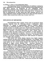
The spectral characteristics of such a multilayer stack are shown in Fig.
11-12 for the case
of
a variable number of alternating layers of ZnS and MgF,
.
Also
shown is a portion of the microstructure
of
a multifilm stack composed
of
these materials. It is clear that the magnitude
of
the reflectance increases with
the number of layers. The number
of
sideband oscillations outside the high-re-
flectance zone also increases with number of layers. The spectral width of the
high reflectance zone is a function
of
the ratio
of
the refractive indices of the
involved films, and there are a couple of practical ways to extend it. One is to
select materials with
nH
and
nL
that
are
higher and lower, respectively, than
those
of
ZnS and MgF,
.
Another is to broaden the basis of design to include
several wavelengths. In such a case the dielectric stack would be composed of
staggered layer thicknesses
so
that consecutive maxima would overlap. In this
way 15 layers
of
ZnS and Na,AIF, with different optical thicknesses can
be
used to span the visible range. By similar methods dielectric mirrors are
designed to operate in the infrared or ultraviolet with very small residual
11.4
Multilayer Optical Film Applications
535
.
""
Y
90-
00
-
v
s
70-
40-
20
-
os
11
11
I
I
11
1
11
I
I
11,
I
0 10 20 30 40 50 60 70 00 90 100 110 120 130 140 150 160 1701
PHASE THICKNESS
16/21
I
I1
I
I
1
I
I
1
5000
1000
000
600
460
400 300 250 230
WAVELENGTH
(nm)
(4
(b)
Figure
11-12.
(a) Spectral characteristics of multilayer stacks formed of alternating
h/4
layers of ZnS and MgF,
0:
glass
(n,
=
1.52)
as a function of
2
?rnd/h.
Normally
incident light with
h
=
4600
A
assumed. Number of layers in each stack is indicated.
(From Ref.
18).
(b)
Transmission electron micrograph of a replica of the ZnS/MgF,
multilayer cross section. (Courtesy of
K.
H.
Guenther).
absorption. In reducing the difference between
nH
and
nL,
a narrow-band
reflection filter, the minus filter
of
Fig.
11-1
1,
can
be
generated.
Multilayer dielectric interference systems are ideally suited as reflection
coatings for fully reflecting and partially transmitting laser mirrors. Negligible
absorption means that reflectances of almost
100%
can
be
achieved. Typical
536
Optical
Properties
of
Thin
Films
material combinations have included ZnS-ThF,
,
Ti0,-SiO,
,
and other oxide
combinations in either broad or narrow spectral-band mirror configurations.
Much attention must
be
paid to substrates employed where low light scattering
and good film adhesion are critical requirements.
11.4.4.
Cold Light and Heat
Mirrors
There are two noteworthy practical variants of dielectric mirrors-cold light
and heat mirrors. The cold light mirror spectral characteristics are shown in
Fig.
11-13.
It has high reflectivity for visible light but a high transmission for
IR radiation. These characteristics are particularly suited to motion picture or
slide projectors in order to avoid overheating the photographic emulsion.
Intense light sources (e.g., carbon arc, xenon lamps) emit IR radiation in
addition to visible light and the heat generated by the former must be
dissipated.
A
cold mirror is thus placed at
45"
in front
of
the light source. The
heating infrared radiation passes through it while the nonheating visible light
reflects
off
to illuminate the object. Metals cannot
be
used because they are
good reflectors of the IR. Interference films are required and these must have
low absorption in the IR. In addition the first film on the glass should be
material having high reflectance in the visible and transmitting in the IR (e.g.,
Ge or Si).
A
few alternating
X/4
amplifying film layers on top of this help
achieve the high reflectance over a suitably wide visible bandwidth.
Heat or
dark
mirrors have characteristics that are inverse to those of cold
mirrors (Fig.
11-14).
There are two approaches to achieving high visual
transmittance simultaneously with high
IR
reflectance. The first is
to
employ
COLD
MIRROR
0.4
0.5 0.6
0.7
0.8
0.9
1.0
WAVELENGTH IN MICRONS
Spectral
characteristics
of
a
cold
light
mirror.
(From
Ref.
19
0
Figure 11-13.
burin
Publishing
Co.
Inc.).
11.4
Multllayer Optical
Film
Appllcalions
537
HOT
MIRROR
WAVELENGTH IN
MICRONS
Figure
11-14.
Spectral characteristics of
a
heat or dark
mirror.
(From Ref.
19
0
Laurin
Publishing
Co.
Inc.).
interference phenomena in an all-dielectric film stack. The second makes use
of the properties of transparent conducting films. Consider the application to
a
low-pressure sodium vapor lamp, which consists
of
a Na-filled discharge tube
within an evacuated glass envelope. For optimum Na pressure, the discharge
tube must be kept at a temperature of about
260
"C.
The necessary power for
this is supplied by the gas discharge. However, the tube loses heat through
radiation of energy in the far IR. Therefore, to conserve energy the inside of
the envelope is coated
so
as to enable the (cold) yellow light to emerge while
reflecting the
IR
back to the discharge tube.
In another energy-saving application, home window panes coated with heat
mirrors would reflect heat back into the house in the winter. In the summer the
window could be reversed
so
that the coating could reflect the IR from the sun
and help provide interior cooling.
11.4.5.
Photothermal
Coatings
The direct conversion of solar radiation into energy for heating or cooling
applications is a vital component of energy supply and conservation strategies.
Coatings play an important role in photothermal conversion, and it
is
appropri-
ate to briefly consider them because of their outward resemblance to the above
mirrors. They differ because the substrate is usually
a
heat-absorbing metal
panel. In addition, they are designed for optimal response to the spectral
characteristics
of
sunlight. The situation can
be
modeled by noting that
A
+
R
=
1,
where
A
is the coating absorbance. Strong absorption of sunlight
in the range of
0.3-2.0
pm is required to heat the substrate. However, a
portion of the heat will
be
lost by reradiation from the surface, reducing the
538
Optical Properties
of
Thin
Films
overall conversion efficiency. Therefore, a second requirement of the coating
surface is a low emittance or high reflectivity in the spectral region of
reradiation-2-10 pm. Emittance
E
is defined by the ratio of power emitted
by a given surface to that of a blackbody. Clearly, higher values of
A
/E
result
in desired higher equilibrium temperatures reached by the coating. (The
similarity to the radiation limited temperature reached during sputtering should
be
noted.
See
p. 117.)
Solar absorbing coatings have been produced by physical and chemical
vapor deposition techniques as well as by electroplating, anodization, acid
dipping, painting, and spraying. Compositions include NiS- ZnS (black Ni),
Cr-Cr oxide (black Cr), Al,O,-metal, SiO-metal, PbS, and Zn to name a
few. Typical absorptances range from
0.90
to
0.98,
and emittances
of
0.1 are
common.
11.4.6.
Optical
Filters
Filters are optical components that selectively change either the intensity
or
spectral distribution of light emitted by a source. They can be designed to
change spectral characteristics over the total, a substantial fraction of the total,
or
only over an extremely narrow portion of the total wavelength range.
Respective examples of these are shown in Fig.
1 1-1
1 and include
1.
Neutral
or
gray filters, which reduce the light intensity equally for all
2.
Broadband, short- or long-wave pass filters. The cold light and heat
mirrors
3.
Narrow bandpass
or
monochromatic filters.
wavelengths.
just described are specific examples.
Thin film coatings to achieve these ends consist of thin metal
films,
dielectric films, multilayer metal and dielectric film combinations, and all
dielectric film stacks. These can
be
deposited on clear and colored glass
substrates to produce
the
desired effects. In the very broadest usage
of
the
term, filters can
be
thought to include mirrors and antireflection coatings but
these optical devices
are
usually considered separate categories. Since the
subject
is
a
large
one,
discussion
will
be
limited.
7
7.4.6.7.
Neutral
Filters.
Neutral density filters consist
of
single metallic
films
of
varying thicknesses on glass. They produce the desired uniform
attenuation
of
light by reflection and absorption effects. Metals such as Cr, Pd,
Rh,
and Ni-Cr alloys are used for this purpose. The filter is usually character-
11.4
Multilayer
Optical
Film
Applications
539
ized by its optical density, which is defined by log
I/&
(see
Eq.
11-3).
Important applications of neutral filters can
be
found in spectroscopy equip-
ment, color photography, and microscopy. They can be fabricated to span the
visible
as
well as IR and UV portions of the spectrum.
17.4.6.2.
Broadband
Filters.
Low- and high-pass edge filters fall into the
category of broadband filters. They are characterized by an abrupt change
between a region
of
high transmission and a region where light is rejected.
Such an edge band filter is shown in Fig. 11-15, and is used to block out UV
radiation from a mercury light
source.
Similar filters can create distinctions in
light transmission and rejection between the visible and IR and well as across a
narrow wavelength range entirely within the visible, IR
or
UV. Filters
manufactured for the near-IR and visible employ Ag films, whereas Al is used
for those operating in the UV. These
metals
are coated with dielectrics such as
MgF,, PbF,, cryolite,
and
ThF,.
In
the
IR,
Ge, Si, and Te layers find
common use. All dielectric multilayer mirror systems can
also
be used as the
basis for the design
of
edge filters, particularly those that require a sharp
transmission between the pass and stop portions
of the transmittance curves.
The way
to
sharpen the transition is to increase the number of layers in the
stack. Unfortunately, the amplitude and frequency of the sideband oscillations
in
the
passband
also
increase when this is done. Suppression
of
these oscilla-
tions or “ripple” is one of the major concerns of filter designers.
Other common broadband filters consist of colored absorbing
glasses
in
combination with interference edge filters or a pair of interference edge filters.
WAVELENGTH
(nm)
Figure
11-1
5.
Mercury lamp light source spectrum and
UV
blocking filter character-
istics.
(From
Ref.
5).
540
Optical Properties
of
Thin Films
The latter can be made to have the inverse characteristics of the alldielectric
mirror stack-i.e., with high transmission instead of high reflectance, and vice
versa. Wide ranges of the visible or
IR
can be selectively filtered this way.
There are many applications
of
wide-band filters in color photography,
TV
cameras, color separation schemes,
studio
illumination, microscopy, etc. We
close with an additional pair of applications. The first involves using a filter to
minimize heating of Si solar cells by eliminating the IR component from
sunlight. Electron-hole pairs are only generated for wavelengths less than
1
pm and the cell is more efficient when
cool.
An edge
filter
with a cutoff
beyond this wavelength would be called for. Such
a
filter can
be
combined
with an antireflection coating to optimize efficiency.
A
second interesting example involves filters employed in fluorescence
microscopy (Ref.
5).
Sometimes the excitation
and
emission wavelength bands
used are
so
closely spaced that, unless precautions are taken,
the
two overlap,
resulting in swamping
of
the fluorescent light output by the strong source light.
This happens for example with FTIC, a fluorochrome employed in immunoflu-
orescence. For excitation, maximum absorption occurs at
0.490
pm, and the
emission maximum occurs at
0.520-0.525
pm.
An edge fdter with an exceed-
ingly high steepness at
-
0.500
pm is required. A filter with no less than
31
Ti0,-SiO, layers is required to suppress unwanted source radiation to levels
of
-
0.1
%
in the region where excitation occurs.
77.4.6.3.
Narrow-Band
Filters.
These filters can be traced back to the use
of the Fabry -Perot interferometer. The optical arrangement involved consists
of two parallel facing, partially transmitting silver film mirrors separated by
an
air or dielectric layer. Light incident normally on this pair of mirrors is
strongly transmitted only in a very narrow spectral range. This is a very
surprising result, since one would expect the mirrors to reflect and filter the
light; what little light the
first
allowed to
be
transmitted would
be
reflected
back by the second mirror
so
that none would get through. This does not
happen, however. Assume, for example, that the mirrors transmit
2%
of the
light and that
1
W
of
monochromatic light is incident. If the distance or cavity
between mirrors
is
not
an
integral number
of
wavelengths long,
the
light
waves
that penetrate the first mirror will bounce to and
fro
and soon
be
out of phase.
Of the
0.02
W
incident on the second mirror,
O.OOO4
W
will eventually be
transmitted.
If
the cavity is, however, resonant, all waves will be in phase and
their amplitudes will add,
so
that perhaps
50
W
will circulate between the
mirrors. Then
2%,
or approximately
1
W,
will be transmitted. This effect
is
11.4
Multilayer Optlcal
Fllm
Appllcatlons
541
relied upon in laser operation. The transmission maxima occur for
X,
=
2nd,
where
nd
is the effective optical thickness of the spacer layer.
Narrow bandpass filters can
be
fabricated in virtually any region
of
the
spectrum. Figure 11-9 gives us a clue as to what is required.
As
the refractive
index of the deposited interference film increases, not only does the reflectance
increase at
X/4
but the region of high transmittance at
X/2
narrows consider-
ably. The case where
r,
=
-r,
=
-0.98
combines the high transmittance
over a narrow range. Two conditions must
be
fulfilled
to achieve this. First the
optical structure must
be
symmetric about the spacer layer
so
that
1
r,
I
=
I
r2
I
.
Second, high reflectance is required at each layer-substrate interface. Metal
film mirrors can accomplish this but at the expense of some absorption losses.
A
desirable alternative when low loss is essential is to employ an all-dielectric
film stack. The role of the stratified dielectric structure is to increase the
reflectance by essentially raising the effective index of refraction as noted
earlier.
11.4.7.
Conclusion
In virtually all of the applications in this chapter the individual dielectric films
have traditionally been modeled solely in terms of two parameters-thickness
and refractive index. This simple approach will be inadequate in the future
because of the steadily increasing performance requirements of advanced
precision optical systems. The gap between theoretically predicted characteris-
tics and performance attained in practice can be narrowed only by modifying
the basic theory to include second-order effects. These include
1. Dispersion or the variation of refractive index with wavelength
2.
Small
amounts of absorption
3.
Inhomogeneities resulting in the variation of refractive index throughout
4.
Anisotropy in the refractive index with direction
of
radiation
5.
Departures
from
perfectly planar boundaries
single films
Concurrently, great strides have been made in improving the quality
of
optical materials and in controlling deposition processes. Likewise, characteri-
zation techniques have reached such high degrees of precision that measure-
ments have exposed weaknesses in the theory and design of multilayer film
systems. Computer-aided interactive feedback integrating
theory,
design, pro-
cessing and performance of multilayer coatings is essential. In these ways,
542
Optlcal
Propertlea
of
Thin
Films
experience and
art,
which have
so
long and
so
well served the optical coating
field, are being supplanted by more exact scientific approaches.
1.
Schematically sketch the optical absorption of
two
semiconductor films as
a function of wavelength if one film
is
doped more heavily than the other.
Is
there a difference in absorption at the wavelength corresponding
to
Eg?
2.
a. If the index of refraction of a GaInAsP semiconductor laser is
n,
=
3.52,
what
is
the reflectance at
the
air interface?
b.
To
reduce
R
at the laser exit window a single-layer
AR
coating
is
required. What index of refraction and film thickness would you
recommend for a 1.3-pm device?
3.
Prove that
a. without
AR
coatings, surfaces of higher refracting glasses produce
b.
higher refracting glasses increase the effectiveness of a single
X/4
AR
higher values of
R
than those of lower refracting glasses.
layer.
4.
Compare the spectral response
of
the single
AR
layer
(no
=
l/n,
=
1.38(X/4)/n2
=
1.52)
and the two-layer
AR
coating
(no
=
l/n,
=
1.38(X/4)/n2
=
1.70(X/4)/n3
=
1.52)
by calculating
R
at
X
=
500,
550,
and
600
nm for each. [Note:
The
h/4
layers
are
selected for
X
=
550
nm, and
n
is assumed to
be
independent
of
X.]
5.
A
7.5-cm-long glass slide substrate of index of refraction
n2
=
1.5
is
coated with ZnS for which
n,
=
2.3.
Graph the expected percent re-
flectance
at
0.55
pm
as
a
function
of
position along the slide
if
a. a uniform
2000-fi
film
is
deposited.
b.
a wedge-shaped film (zero thickness at one end,
20004
thick
10
cm
away)
is
deposited.
c.
an evaporated film
is
deposited from a surface source
10
cm direct!y
below
the center
of
the slide. The maximum film thickness is
2000
A.
Exercises
543
6.
7.
0.
9.
For an additional charge lenses on eyeglasses are coated. How does this
enhance wearer personal appearance and vision or extend lens life?
A protected A1 mirror is characterized by no
/nl
/nz
-
ik,
,
with no
=
1,
n,
=
1.52,
n,
=
0.81,
and
k,
=
5.99
at
A
=
0.55
pm.
a. Calculate
rl
,
r2,
and
R.
b. What is
the
reflectance of the mirror?
c. How does
R
for an unprotected mirror compare with the answer to
Part
cb)?
A
step gauge consisting of thermal
SiO,
films on
a
Si substrate, varying
in thickness from
200
to
5000
is viewed with a HeNe laser
(A
=
6328
A).
If the refractive index of Si is
N
=
4.16
-
iO.018,
plot the re-
flectance versus SiO, film thickness.
A thin amorphous Si
(a-Si)
film
(n,
-
ik,)
on
a
(100)
Si
(c-Si) substrate
(n,
-
ik,)
shrinks
in
thickness during solid-phase epitaxial
regrowth
at
elevated temperature.
A
He-Ne laser
(A
=
6328
A)
probe
beam
reflects
from
both the surface and a-c interface establishing interference effects in
the backscattered optical signal.
a. Show that the reflectivity for any given a-Si
film
thickness, d, is given
by
r,
+
r2e-4xk,d/X
-i4an,dfX
1
e
R=[
1
+
e-4rk,d
e
-i4xn,d/X
'
12
b. If N,
=
4.85
-
i0.61
and
N,
=
4.16
-
i0.018,
calculate
R
as a
function of
d
over the range
4000
to
0
A.
Charoacterize the resultant
reflectivity oscillations. [Note: When
d
>
4000
A, there is essentially
no contribution from c-Si and
R
=
0.438.
At
d
=
0,
R
=
0.375.1
c.
Suppose the layers are reversed
and
a
film
of c-Si is at
the
surface on
top of a thicker a-Si substrate layer beneath.
How
does the
R
vs.
d(c-Si) dependence differ from the
R
vs. d(a-Si) dependence
of
the
previous
case?
10.
Ion bombardment deposition of a
(HLH,
etc.) multilayer dielectric stack
of
nine layers of ZnS and
MgF2
on glass
(n,
=
1.52)
raises each of the
respective refractive indices by
4%.
What change in reflectivity can be
expected for such a structure relative to a traditionally evaporated stack?
What if there were only five layers?
544
Optical
Properties
of
Thin
Films
11.
The inner surface
of
an
incandescent lamp bulb
is
coated with a thin-film
sandwich consisting of
ZnS
(0.03
pm
thick)
Ag
(0.02
pm
thick)
ZnS
(0.03
pm thick)
Explain
the
function
of
these layers and
the
overall behavior
of
the lamp.
1
2.
Explain why the thin-film coating consisting of air/SiO( h/4)/Ge(
h/4)/
opaque Al/glass substrate has a reflectance-wavelength response
as
fol-
lows:
Wavelength
%R
13.
Visible
-2
1
pm
80
1.2
pm
90
>
2
pm
>
95
Calculate
R
for the following dielectric stacks.
System No.
of
Layers
n
Substrate
H.L.
X(m)
SH
1
1
CeO,
.Na,AIF6 0.55
SHLH
3
1.52
CeO,
,Na3AIF6 0.55
SHLHLH
5
1.52
CeO,
.Na,AIF6 0.55
SHLHLHLH
I
1
SO
ZnS,
Na,AIF, 0.59
SHLHLH
5
1.45
Ge,
Na3AIF, 2.0
REFERENCES
1
.*
H. A. Macleod, in
Applied Optics and Optical Engineering,
Vol.
X,
eds.
R. R.
Shannon and
J.
C. Wyant, Academic Press, New York
(1987).
2.*
0.
S.
Heavens,
Optical Properties
of
Thin Solid Films,
Dover, New
York
(1965).
3.*
H. Anders,
Thin Films in Optics,
Focal
Press,
London
(1967).
4.*
K.
1.
Chopra,
Thin Film Phenomena,
McGraw-Hill, New York
(1969).
5.*
H.
K.
Pulker,
Coatings
on
Glm,
Elsevier, Amsterdam
(1984).
6.*
H.
A.
Macleod,
Thin-Film Optical Filters,
Adam
Hilger, London and
Macmillan, New York
(1987).
*Recommended
texts
or
reviews.
References
545
7.
G.
Hass,
J.
B.
Heaney, and W.
R.
Hunter, in
Physics
of
Thin
Films,
Vol.
12,
eds.
G.
Hass, M. H. Francombe, and
J.
L.
Vossen, Academic
Press, New York
(1982).
8.
G.
Hass and
E,
Ritter,
J.
Vac.Sci. Tech.
4,
71 (1967).
9.
C.
Kittel,
Introduction to Solid State Physics,
4th ed., Wiley, New
York
(1971).
10.
N.
F.
Mott and
H.
Jones,
The Theory
and
Properties
of
Metals
and
Alloys,
Clarendon Press, Oxford,
(1936).
11.
H. Kostlin and
G.
Frank,
Philips Tech. Rev.
41,
225 (1983/4).
12.
J.
L.
Vossen, in
Physics
of
Thin
Films,
Vol.
9,
eds.
G.
Ham, M.
H.
Francombe, and R. W. Hoffman, Academic Press, New York
(1977).
13.
M. Harris, H. A. Macleod,
S.
Ogura,
E.
Pelletier, and
B.
Vidal,
Thin
Solid Films
57,
173 (1979).
14.
P.
J. Martin,
J.
Mater.
Sci.
21,
1 (1986).
15.
G.
Hass,
Optik
1,
8
(1946);
G.
Hass and M. Waylonis,
J.
Opt.
SOC.
Am.
51,
719 (1961).
16.
G.
L. Olsen and 3.
A.
Roth,
Mat.
Sci.
Repts.
3,
1 (1988).
17.*
P.
H. Lissberger,
Rep. Prog. Phys.
33,
197 (1970).
18.
S.
Penselin and
A.
Steudel,
2.
Phys.
142,
21 (1955).
19.
The Optical Industry and Systems Purchasing Directory-Encyclopdia
(1979).
hapter
12
1
Metallurgical and
Protective
Coatings
12.1.
INTRODUCTION
Paralleling the dramatic development
of
thin-film technology in microelectron-
ics have been the no less than remarkable advances in what may be conve-
niently called metallurgical and protective coatings. The unusual materials
which comprise these coatings are drawn from several classes of solids and
include ionic ceramic oxides (e.g.,
Al,O,
,
ZrO,
,
TiO,), covalent materials
(e.g., Sic, BC, diamond), transition metal compounds (e.g., Tic, TiN,
WC)
and metal alloys (e.g., CoCrAlY, NiA1, NiCrBSi). As a whole they are
characterized
by
extremely high hardness, very high melting points, and
resistance to chemical attack, attributes that have earmarked their use in critical
applications where one or more of these properties is required; correspond-
ingly the respective categories
of
hard, thermal, and protective coatings denote
the functions to which they
are
put. Hard coatings
of
TiN and Tic, for
example,
are
used to extend
the
life
of cutting tools, dies, punches,
and
in
applications such as ball bearings to minimize wear. The collection of coated
cutting tools and dies shown in Fig.
12-1
is representative
of
the
widespread
commercial use
of
this technology in machining
and
forming
operations.
Thermal coatings find extensive use in gas turbine engines where they help to
547
548
Metallurgical and Protective Coatings
J
Figure
12-1.
(Left)
Assorted cutting and forming tools coated with TiN and multi-
layer coatings. (Courtesy Multi-Arc Scientific Coatings). (Top right)
HSS
forming and
sheet metal dies coated with TiN and Tic. (Courtesy Ti Coating Inc.) (Lower right)
multilayer coated cutting tool inserts. (Courtesy of
S.
Wertheimer, ISCAR Ltd.)
improve the performance and extend the life of compressor and turbine
components.
As
the name implies, protective coatings
are
intended to defend
the underlying materials, usually metals, from harsh gaseous or aqueous
environments that cause corrosive attack. Such coatings have found applica-
tions in chemical and petroleum industries, coal gasification plants, as well as
in nuclear reactors.
Employing coatings represents a significant departure from traditional engi-
neering design and manufacturing practices. Processing components beyond
the primary manufacturing steps of casting, forging, extrusion, machining and
grinding, pressing and sintering, etc., has generally been resisted. This is due
in part to a reluctance to tamper with the product, and to leave well enough
alone.
A
compelling case was not made for the cost effectiveness
of
additional
12.1
Introduction
549
treatments. However, more recently several important factors have combined
to firmly establish the practice of modifying the surface properties of engineer-
ing materials and components.
1.
In many critical applications the design specifications
call
for properties that
are simply beyond the capabilities
of
the commonly available and routinely
processed materials. The new limits
of
behavior demanded can be met by
the use of the unusually hard, temperature- and degradation resistant
materials noted earlier. However, these materials
are
extremely difficult to
fabricate in bulk form.
2.
Concerns
of
limited availability of strategic materials, the thrust toward
energy efficiency and independence, and an increasingly competitive world
economy have exerted a strong impetus to considerably tighten engineering
design, improve performance, and economize on materials utilization.
3.
High-quality coatings possessing fewer surface imperfections than compara-
ble pressed and sintered bulk parts made from powder, can now
be
reproducibly deposited. This is due to the advances made in our basic
understanding of the deposition processes and the development of improved
coating and deposition techniques.
4.
The commercial availability of the necessary deposition chambers or reac-
tors, hardware, computer-controlled processing equipment, and high-purity
sources of precursor gases, powders and sputtering targets has facilitated
the
option of employing coatings.
Various combinations
of
the above factors have then resulted in the marriage
of
coatings to the underlying base materials, each with their particular set of
desirable and complementary properties. For example, many structural materi-
als with adequate high-temperature mechanical properties simply do not have
the ability to withstand high-temperature oxidation, corrosion, particle erosion,
and wear. On the other hand, the materials that do
possess
the environmental
resistance either do not qualify as structural materials because of low toughness
or,
if they do, are prohibitively expensive to fashion in bulk form.
Before we turn to the main subjects
of
the chapter, it is worth noting some
of
the similarities and differences between the present mechanically and environ-
mentally functional
coatings,
and
the
thin
firms
of
prior book chapters.
In
common, many coatings are deposited by the same type of physical
(PVD)
and
chemical
(CVD)
vapor deposition techniques. Adhesion
to
the substrate,
development
of
desirable structure and properties, and meeting performance
standards are universal concerns. Among the differences are the following:
1.
The coatings we will
be
considering are far thicker than thin films. Whereas
a couple
of
microns, at most,
is
the
arbitrary upper limit
to
what
we
have
550
Metallurgical
and Protective
Coatings
called films, coatings typically range from several to tens and
even
hun-
dreds of microns in thickness.
2.
The maintenance of precise coating thickness and uniformity
is
not usually
a major concern. There is generally a broad range of acceptable coating
thicknesses. This
is
in contrast to the critical thickness tolerances and
uniform coverage that must be achieved in optical and microelectronic
films.
3.
The substrate is frequently an integral part of the coating system. In
diffusion coatings, for example, metalloid as we11 as metal elements are
diffused into the substrate, creating thick, soluteenriched layers beneath the
surface.
4.
For the most part, the substrates employed for hard and protective coatings
are rather special metals and alloys such as tool, high-speed, and stainless
steels; iron-, cobalt-, and nickel-base superalloys; sintered tungsten carbide;
titanium, etc. The use of the term
metallurgical coating
is based in part on
this fact.
5.
There are many methods for producing coatings. In addition to the vapor
phase atomistic deposition processes
(PVD,
CVD) for films, coatings are
also formed by
a. Deposition of particulates (e.g., by thermal spraying of metal or oxide
powders either through a hot flame or an even hotter plasma)
b. Immersion
of
substrates in molten baths or heated solid packs
c.
Electrolytic processes such as electroplating, fused salt electrolysis, and
d. Miscellaneous processes, e.g., welding and enameling
electroless plating
6.
Except for epitaxial semiconductor films, most thin-film depositions are
carried
out
at relatively low-substrate temperatures. Metallurgical and
protective coatings, however, are frequently deposited at elevated tem-
peratures. Certainly this is true of the CVD coatings, and, therefore,
atomic interdiffusion and reactions generally occur at the interface
between coating and substrate. Compositional change can either be
beneficial or detrimental to adhesion and coating properties depending
on
the
materials involved.
The bulk
of
the chapter will
be
concerned with hard coatings and issues
related to them. Somewhat lesser emphasis
is
placed on thermal and environ-
mental coatings. To limit the treatment to manageable proportions, we deal
with properties and the phenomena they influence in a fundamental way. The
more widely used vapor deposition processes will be primarily discussed to
12.2
Hard Coating Materials
551
maintain a consistency with prior chapters. Electrodeposition, for example,
will not be mentioned again, since there is already a huge and accessible
literature on
the
subject. Case histories and examples are always interesting
and will be interspersed where appropriate. The specific topical outline of the
rest of the chapter is
12.2.
Hard Coating Materials
12.3.
Hardness and Fracture
12.4.
Tribology of Films and Coatings
12.5.
Diffusional, Protective, and Thermal Coatings
12.2.
HARD COATING MATERIALS
12.2.1.
Compounds and Properties
Hard coating materials can be divided into three categories, depending on the
nature of the bonding. The first includes the
ionic
hard oxides of Al, Zr, Ti,
etc. Next are the
covalent
hard materials exemplified by the borides, carbides,
and nitrides of
Al,
Si, and
B,
as well as diamond. (See Section
14.2.)
Finally,
there are the
metallic
hard compounds consisting
of
the transition metal
borides, carbides, and nitrides. Typical mechanical and thermal property
values for important representatives of these three groups of hard materials are
listed in Table
12-1.
The reader should be aware that these data were gathered
from many sources (Refs.
1-6)
and that there is wide scatter in virtually all
reported property values. Differences in processing (e.g.,
CVD,
PVD, and
sintering of powders), variations in structure (e.g., grain size, porosity,
density, defects) and composition (e.g., metal-nonmetal ratio, purity), to-
gether with statistical error in measurement, contribute to the uncertainties.
Perusal of this tabulated information leads to the following broad conclusions:
1.
All
of these compounds have extremely high hardnesses. This can
be
appreciated by noting that heat-treated tool steel has a hardness of about
H,
=
850.
Hardness is the most often quoted material property
of
hard
coatings. Therefore, Section
12.3
has been specially reserved for an
extensive discussion of the concept of hardness, the technique
of
measure-
ment, and the significance of its magnitude in coatings.
2.
These compounds have very high melting points and decomposition temper-
atures. For example, the decomposition temperatures of TaC,
HfC,
and
diamond exceed the melting point for tungsten
(MP
=
3410
"C).
3.
The modulus of elasticity is lowest for the ionic solids. In comparison, only
Table
12-1.
Mechanical and Thermal Properties
of
Coating Materials
VI
B
I-
Thermal
H
=
Hoe-“7
Melting
or
Decomposition (Eq.
12-4)
Young’s Expansion Thermal Fracture
Temperature Hardness
HO
a
Density Modulus Coefficient Conductivity Toughness
Material
(“C)
(kg-mm-’) (kg-mm-2) C-’) (g-cm-’) (kN-mm
’)
(10
-6
K-
’)
(Wm-’
K
’)
(MPa-m”’)
Ionic
2047 2100 2300 7.85 3.98 400 6.5
-
25 3.5
a02
2710 1200 5.76 200 8.0
1.5
4-12
TiO,
1867
1100
1250
5.99 4.25 200 9.0
9
SO, 1700 1100 2.27 15
1
0.55
2
<1
C
(Diamond)
3800
-
8000 3.52 1050 1
1100
B4N
2450
-
4000 2.52 660
5
BN
2730
-
5000
3.48 440
Sic 2760 2600 2800 0.90 3.22 480 5.3 84 3
Si,N,
1900
1700 1900 2.79 3.19
310
2.5 17 4
AIN
2250 1200 3.26 350 5.7
Metal
Compounds
Covalent
=
TiB
,
3225 3000 3500 18.9 4.5
560
7.8
30
g
Ti
C
3067 2800 3300 18.3 4.9 460 8.3 34 0.46
z
Q,
TIN
2950
2100
2100 23.5 5.4 590 9.3
30
HfN
2000 8.57 6.9 13
‘D
m
a
HfC
3928 2700 3000 14.7 12.3 460 6.6
TaC
3985 1600 1800 6.75 14.5
560 7.1 23
0.
wc
2776 2300 2350 3.62 15.7
720 4.0 35
s
2
Substrate
Materials
High-speed
0
Steel
1400 900 7.8
250
14
30
50-170
0
WC-6%Co
1500
640
5.4
80
11.4
8
Ti
1667 25
0
4.5
120
11
13 80
2
>
100
m
n
(D
2
(D
Ni Superalioys
1280 7.9 214 12 62