Theory and Design of CNC Systems Part 2 doc
Bạn đang xem bản rút gọn của tài liệu. Xem và tải ngay bản đầy đủ của tài liệu tại đây (1.41 MB, 35 trang )
18 1 Introduction to NC Systems
The detector can be attached to the shaft of a servo motor or the moving part and
the control system can be categorized into four types according to the location at
which the detector is attached.
1.4.1 Semi-closed Loop
The semi-closed loop is the most popular control mechanism and has the structure
shown in Fig. 1.11a. In this type, a position detector is attached to the shaft of a servo
motor and detects the rotation angle. The position accuracy of the axis has a great
influence on the accuracy of the ball screw. For this reason, ball screws with high
accuracy were developed and are widely used. Due to the precision ball screw, the
problem with accuracy has practically been overcome.
If necessary, pitch-error compensation and backlash compensation can be used
in NC in order to increase the positional accuracy. The pitch-error compensation
method is that, at the specific pitch, the instructions to the servo driver system
are modified in order to remove the accumulation of positional error. The backlash
compensation method is that, whenever the moving direction is changed, additional
pulses corresponding to the amount of backlash are sent to the servo driver system.
Recently, the usage of the Hi-Lead-type ball screw with large pitch for high-speed
machining has increased.
1.4.2 Closed Loop
The performance of the semi-closed loop depends on the accuracy of the ball screw
and it is possible to increase the positional accuracy via pitch compensation and
backlash compensation. However, generally speaking, the amount of backlash can be
varied according to the weight of the workpiece and location and accumulation pitch
error of the ball screw is varied according to the temperature. In addition, because
the length of the ball screw is limited for practical reasons, a rack and pinion driving
system is used in large-scale machine tools. However, the accuracy of the rack is
limited. In this case, the closed loop shown in Fig. 1.11b is applied. In the closed
loop, the position detector is attached to the machine table and the actual position
error is fed back to the control system. Closed loop and semi-closed loop are very
similar except in the location of the position detector, and the position accuracy of
closed loop is very high. However, the resonance frequency of the machine body,
stick slip, and lost motion have an influence on the servo characteristics because the
machine body is included in the position control loop.
That is, a following error, the difference between the command position and the
detected position, occurs and the servo is rotated at a speed proportional to this fol-
lowing error in order to decrease it. The decreasing speed of the following error is
related to the gain of the position control loop. The gain is an important factor that
1.5 The Components of the CNC system 19
defines the property of the servo system. In general, as the gain increases, the re-
sponse speed and dynamic accuracy increase. However, high gain makes the servo
system unstable. Unstable means hunting, which is impossible to stop at the com-
mand position due to repetitive overshooting and returning. In the closed loop, if the
resonance frequency of the machine driving system is not sufficiently higher than
the gain, the control loop system becomes unstable. In addition, stick slip and lost
motion are the main factors that give rise to hunting. Therefore, it is necessary to
increase the resonance frequency of the machine driving system and, for this, it is
necessary to increase the rigidity of the machine, decrease the friction coefficient of
the perturbation surface, and remove the cause of lost motion.
1.4.3 Hybrid Loop
In closed loop, it is necessary to lower the gain in the case when it is difficult to
increase the rigidity in proportion to the weight of the moving element or decrease
lost motion as in a heavy machine. If the gain is very low, though, the performance
becomes poor with respect to positioning time and accuracy. In this case, the hybrid
loop shown in Fig. 1.11c is used. In the hybrid loop, there are two kinds of control
loop; semi-closed loop, where the position is detected from the shaft of a motor, and
closed loop, which is based on a linear scale. In the semi-closed loop, it is possible to
control with high gain because the machine is not included in the control system. The
closed loop increases accuracy by compensating the error that the semi-closed loop
cannot control. Because the closed loop is used for compensating only positional
error, it is well behaved in spite of low gain. By combining the closed loop and
the semi-closed loop, it is possible to obtain high accuracy with high gain in an ill-
conditioned machine.
1.4.4 Open Loop
Unlike the above-mentioned control loops, open loop has no feedback. Open loop
can be applied in the case where the accuracy of control is not high and a stepping
motor is used. Because open loop does not need a detector and a feedback circuit,
the structure is very simple. Also, the accuracy of the driving system is directly in-
fluenced by the accuracy of the stepping motor, ball screw, and transmission.
1.5 The Components of the CNC system
The CNC system is composed of three units; the NC unit which offers the user inter-
face and carries out position control, the motor unit, and the driver unit. In a narrow
20 1 Introduction to NC Systems
Fig. 1.11 Classification of control mechanism according to position data detection method
sense, only the NC unit is called a CNC system. The contents of this book focus on
the architecture and function of NC and do not include the motor unit and the driver
unit
PLC
NCK
MMI
HiTrol-M100 (Hyundai Motors Co. Ltd.)
PLC
(Programmable
Logic
Control )
NCK
(Numerical
Control
Kernel)
MMI
(Man-
Machine
Interface)
Human
Machine I/O
Servo System
Open
Application
Fig. 1.12 The construction of CNC
1.5 The Components of the CNC system 21
From a functional point of view, the CNC system consists of the MMI unit, the
NCK unit, and the PLC unit, Fig.1.12. The MMI(Man Machine Interface) unit offers
the interface between NC and the user, executes the machine operation command,
displays machine status, and offers functions for editing the part program and com-
munication. The NCK (Numerical Control Kernel) unit, being the core of the CNC
system, interprets the part program and executes interpolation, position control, and
error compensation based on the interpreted part program. Finally, this controls the
servo system and causes the workpiece to be machined. The PLC (Programmable
Logic Control) sequentially controls tool change, spindle speed, workpiece change,
and in/out signal processing and plays the role of controlling the machine’s behavior
with the exception of servo control.
Figure 1.13 shows the conceptual architecture of CNC machine tools from the
hardware and software points of view.
Software
MMI
NCK
Hardware
Position
control
Velocity
control
Amplifier
Servo
motor
M/T
Lamp, SOL, Relay
Tachometer
Encoder
Linear scale
CNC System
Motor & Drive
System
Machine
Tools
PLC
CPU Memory
NCK
CPU Memory
PLC
PLC operating system
Sequence program
CPU
MMC
Display & Operating
Part Pro-
gramming
Service
Control
Communication
Mechanical comp.
Sensing algorithm
Control algorithm
Code parsing
Interpreter
Interpolation
I/O
Inter-
face
Host
computer
Machine
panel
Input
from M/T
CRT/MDI
Memory
Machine
parameter
Diagnosis
Fig. 1.13 The components of a CNC system
From the hardware point of view, CNC machine tools consist of CNC, motor drive
system, and machine tools. The output of the position control, being the end func-
tion of the CNC system, is sent to the motor drive system, the motor drive system
operates a servo motor by velocity control and torque control, and, finally, the servo
motor makes the moving part move via the power-transmission device. In the CNC
system, the processor modules that process the functions of the MMI unit, NCK unit,
and the PLC unit consist of a main processor, a system ROM and a RAM that stores
22 1 Introduction to NC Systems
user applications, part programs and PLC programs, respectively. The process mod-
ule is connected with an interface that is equipped with key input, display control,
external input and system bus. Therefore, the architecture of a CNC system is simi-
lar to that of a multi-process computer. The CNC system also has an Analog/Digital
input/output device for direct communication with external machines and a commu-
nication interface for linking an external motor driving device with an input/output
module.
In the CNC system, initially velocity commands in analog format were used for
transmitting signals to the motor driving system. However, recently, because noise
occurs while transmitting analog signals, not only are digital signals used for ve-
locity command but also digital communication is used for communication between
the CNC system and the motor driving system. SERCOS is the most popular digital
communication mechanism and has come to be a de-facto standard. In digital com-
munication there is an advantage that it is possible to exchange a variety of data and
remove noise by using optical cables. Therefore, it is possible to set the parameters
of the driving system in NC, monitor the status of the driving system, and increase
accuracy by removing noise.
By expanding the concept of digital communication, the communication mech-
anism has been applied to input/output devices. That is, the connection between a
CNC system and a variety of sensor and mechanical devices is done via only one
communication line. For this communication mechanism, a standard communica-
tion protocol is essential and various protocols such as Profi-Bus, CAN Bus, and
InterBus-S were introduced.
From the software point of view, the CNC system can be shown as in Fig. 1.13.
The CNC system consists of MMI functions that support user operation and program
editing and display machine status, NCK functions that execute interpretation, inter-
polation and control, PLC functions that carry out sequential logic programs. In the
following sections, these will be addressed in detail.
1.5.1 MMI Function
The MMI unit offers the user interface that is needed when a user operates machine
tools. Therefore there are many kinds of user interface based on the design concepts
of the CNC maker. Functions of the user interface are generally classified into five
groups.
1. Operation functions: These functions are used very frequently and support oper-
ation of the machine and the display that shows the machine status. Figure 1.14a
depicts the status of the machine while it is running. In Fig. 1.14a, the position,
distance-to-go, and feed of each axis, spindle speed, the block that is being exe-
cuted, and override status are shown. In addition, functions to help machine op-
eration such as jog, MDI, program search, program editor, and tool management
are provided.
1.5 The Components of the CNC system 23
2. Parameter-setting functions: In the CNC system there are various parameters
for internal use and these are categorized into three kinds: Machine parameters
that are used for setting machine regulation, servo/spindle driving system, tool
offset, work coordinate, and safety boundary; program parameters that should be
set during editing of the part program; and customization parameters that are used
to adapt the machine to user requirements. These functions provide the interface
for setting, storing, and searching parameters. Figure 1.14b shows the display for
searching for internal parameters and modifying them.
3. Program-editing functions: These functions are able to edit and modify the part
program, which is G-code based on the EIA/ISO standard. Practically, it is nec-
essary for the user to know G/M-codes and carry out mathematical calculations
in order to generate the G-code part program. Because mathematical calculation
makes it difficult to edit part programs, CNC has recently begun to employ con-
versational programmingsystems. Figure 1.14c shows the display that the conver-
sational programming system provides in order to edit a part program for drilling.
By interaction with the GUI a user can quickly generate a part program for drilling
without memorizing the input attributes for G-code cycles. Figure 1.14d also
shows the shape calculator to help a user define the geometric shape. Recently,
the conversational programming system has come to be recognized as an essen-
tial function of CNC and therefore, in this book, the design and the example of a
feature-based conventional programming system will be addressed in detail.
4. Monitoring and alarm functions: the CNC system always informs a user of the
machine status by monitoring and, if need be, these functions execute the neces-
sary tasks and inform the user of the result. These functions are essential when
machine tools are executing at high speed. These functions play the role of provid-
ing monitoring information such as the alarm status, emergency recovery method,
PLC status, and ladder diagram under execution.
5. Service/utility functions: Besides the other four essential functions, many useful
functions are provided to assist users. The DNC function for transmitting the part
program, which is edited externally, to the CNC, the file service for copying inter-
nal parameters to the outside, and the communication function for communicating
with computers belong to these functions.
1.5.2 NCK Function
In general, the NC system interprets the input data, keeps them in memory, sends
commands to the driving system, and detects feedback signals from the drive sys-
tem. The NC system also performs logical decision making such as when coolant
is provided and when the spindle starts rotating and mathematical calculations for
acceleration control and interpolation of lines, circles and parabolae. Therefore, the
NCK unit has the task of being in charge of the servo and driving control and the
PLC unit has the task of being in charge of logic control, so the burden that occurs
24 1 Introduction to NC Systems
(a) (b)
(c) (d)
Fig. 1.14 Man-Machine Interface (HiTrol-M100) (a) Operation functions, (b) Parameter setting
functions, (c) Drilling editing functions, (d) Geometric shape calculator
during control is adequately balanced. The functional blocks and the data flow of
the NCK unit, being the key unit of the CNC system, are shown in Fig. 1.15. The
interpreter, interpolator, acceleration/deceleration controller, and position controller
are the main functions of the NCK unit.
1. An interpreter plays the role of reading a part program, interpreting the ASCII
blocks in the part program, and storing interpreted data in internal memory for
the interpolator. In general, NC issues the orders related to the interpreted data
and the interpreter reads and interprets the next block while the command is be-
ing performed. However, if the time to interpret the block is longer than the time
to finish the command, the machine should wait for the completion of interpre-
tation of the next block so that a machine stop cannot be avoided. Therefore, in
order to prevent machine tools from stopping, a buffer that temporarily stores the
interpreted data is used. The buffer, called the internal data buffer, always keeps
asufficient number of interpreted data and all interpreted data are stored in the
buffer. Details will be given in Chapter 2.
2. An interpolator plays the role of sequentially reading the data from the internal
data buffer, calculating the position and velocity per unit time of each axis, and
1.5 The Components of the CNC system 25
storing the result in a FIFO buffer for the acceleration/deceleration controller. A
linear interpolator and a circular interpolator are typically used in an NC system
and a parabola interpolator and a spline interpolator are used for part of an NC
system. The interpolator generates a pulse corresponding to the path data accord-
ing to the type of path (e.g. line, circle, parabola, and spline) and sends the pulse
to the FIFO buffer. The number of pulses is decided based on the length of path
and the frequency of the pulses is based on the velocity. In an NC system, the
displacement per pulse determines the accuracy; for example, if an axis can move
0.002 mm per pulse, the accuracy of the NC system is 0.002 mm. In addition, the
NC system should generate 25000 pulses for the moving part to move as much
as 50 mm and 8333 pulses per second to move at a speed of 1m per minute. In
Fig. 1.15, the data in the FIFO buffer is transmitted to the next function via a fine
interpolator, which interpolates precisely the interpolated data and, if not neces-
sary, does not have to be implemented. Details will be given in Chapter 3.
3. If position control is executed by using the data generated from the interpola-
tor, large mechanical vibration and shock occur whenever part movement starts
and stops. In order to prevent mechanical vibration and shock, the filtering for
acceleration/deceleration control is executed before interpolated data is sent
to the position controller. This method is called the “acceleration/deceleration-
after-interpolation” method. An “acceleration/deceleration-before-interpolation”
method exists too, where acceleration/deceleration control is executed before in-
terpolation. These two methods will be addressed in Chapter 4 in detail.
4. The data from an acceleration/deceleration controller is sent to a position con-
troller and position control is carried out based on the transmitted data in a con-
stant time interval. A position control typically means a PID controller and issues
velocity commands to the motor driving system in order to minimize the position
difference between the commanded position and the actual position found from
the encoder.
However, the problems of noise cannot be avoided by using an analog signal.
Chapter 5 will address this subject in detail.
1.5.3 PLC Function
The logic controller is used to execute sequential control in a machine and an indus-
try. In the past, logic control was executed by using hardware that consisted of relays,
counters, timers, and circuits. Therefore, it was considered as a hardware-based logic
controller. However, recent PLC systems consist of a few electrical devices including
microprocessorsand memory,able to carry out logical operations, a counter function,
a timer function and arithmetic operations. Therefore, a PLC system can be defined
as a software-based logic controller. The advantages of PLC systems are as follows:
Flexibility: The control logic can be changed by changing only a program.
26 1 Introduction to NC Systems
System
memory
Part
program
D.P.R
MMI
Internal
data
block
D.P.R
PLC
FIFO block
Com.
task
Interpreter
task
Memory mapped I/O
Non-cyclic
task
Cyclic
task
Interpolation task
Signal
read
Signal
write
Rough IPO
routine
Position control task
Fine
IPO
routine
Acc/Dec
routine
Position
control
routine
NCK software
MPG,
Fast D.I. Fast D.O.
Encoder
counter
D/A
converter
Fig. 1.15 NCK functional blocks
Scaleability: The expansion of a system is possible by adding modules and
changing programs.
Economic efficiency: Reduction of cost is possible due to the decrease in design
time, high reliability, and easy maintenance.
Miniaturization: The installation dimension is smaller compared to a relay con-
trol box.
Reliability: The probability of failure occurrence due to bad contact decreases
because of using a semiconductor.
Performance: Advanced functions such as arithmetic operations and data editing
are possible.
The hardware architecture of the PLC unit of an NC system comprises a mi-
croprocessor, a system memory, a program memory, and an input/output module as
shown in Fig. 1.13. As soon as the power is turned on, the system memory sets
the PLC hardware environment and the program memory, manages input/output, re-
lay/timer/counter and stores a user program and the data to be interpreted by the
microprocessor. The input/output module manages the interface with limit switch,
relay, and ramp.
The function modules that are executed in a PLC unit can be defined as shown in
Fig. 1.16 and are summarized below. Initially, a user creates the application program
used in the PLC unit by using an external PLC program editor and inputs the appli-
cation program to the PLC unit. At this stage, a specific device is used for helping
the user to edit the program and is called a programmer or loader. The program-
mer consists of the editor that creates a program and the compiler that converts the
program into the PLC-interpretable language. The reason why a compiler is used is
that a compiled program is more efficient and hence the PLC can run the program
quickly. The compiled PLC program is transmitted to the CPU module. In addition,
1.5 The Components of the CNC system 27
the status of the PLC that is being executed in the CPU module is sent to the PLC
program for a user to monitor the activity status.
The module that reads the program edited by the Loader and executes sequential
logic operations is the Executer, which is the core of a PLC kernel. The Executer
is repeated successively, reading the input points, doing logic operations of the pro-
gram, and sending the results to the output points via the output module.
Executer
PLC Program
Input Module
Editor
Programmer
Programmer
Output Module
Monitor
Compiler
CPU Module
CPU Module
Executer
PLC Program
Input Module
Editor
Programmer
Programmer
Output Module
Monitor
Compiler
CPU Module
CPU Module
Fig. 1.16 The architecture and function of the PLC system
The PLC unit of a CNC system is similar to the general PLC system but there is an
auxiliary controller that assists with part of the functions of the NCK unit. Therefore,
the following functions are necessary:
- Circuit dedicated to communicating with NCK.
- Dual-port RAM for supporting high-speed communication.
- Memory for the exchanged data during high-speed communication with NCK.
- High-speed input module for high-speed control such as turret control.
In practice, according to the decisions of individual CNC and PLC makers, vari-
ous PLC languages are used. Due to this, there is a problem with respect to maintain-
ability and training of users. To overcome this problem, the standard PLC language
(IEC1131-3) was established and usage has spread. The standard, IEC-1131-3, de-
fines five kinds of language; 1) Structured Text (ST), 2) Function Block Diagram
(FBD), 3) Sequential Function Charts (SFC), 4) Ladder Diagram (LD), and 5) In-
struction List (IL 1). Now it is necessary for users to edit programs based on the
standard language and it is required for developers to implement applications for
interpreting and executing a PLC program.
28 1 Introduction to NC Systems
1.5.4 Real-time Control System
In an NC system, the NCK unit, the PLC unit, and the MMI unit should be executed
in constant time intervals. Because of this property, the NC system is a complex
real-time system.
For example, assume that there is a system that has NCK functions such as inter-
pretation, interpolation, and position control and the MMI function. In this system,
fine management of the execution schedule of the modules that occupy the proces-
sor resource is required, as shown in Fig. 1.17. That is, the task scheduling function
that manages the execution of the modules based on predefined time intervals and
priority is necessary.
Position
Interpolation
Interpreter
MMI
Task Priority
System Time
1 2 3 4 5 6 7 8 9
Fig. 1.17 Task scheduling in an NC system
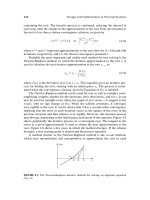
In the above example, the design intention is that the position controller, the inter-
polator, the interpreter, and the MMI have, respectively, the highest, the second, the
third, and the lowest priorities. Also in the design is the feature that the position con-
trol with the highest priority is activated every 1 msec and the interpolator with the
second highest priority every 2 msec, and that the interpreter is executed once every
4 msec. The above-mentioned three tasks are designed to have constant cycle time
(sampling time). The MMI with the lowest priority is designed to use the surplus
processor resource after the cyclic tasks finish. That is, it is designed as a non-cyclic
task.
1.6 The Progress Direction of the CNC System 29
For the NC system design, the modularization of tasks and the system design such
as the allocation of priority for each task, the selection of scheduling method and the
synchronization and communication mechanism among tasks are required.
In this book, the architecture and design of the CNC system and the architecture
and functions of the NCK, the PLC, and the MMI unit will be addressed in detail.
With this information it will be possible for a reader to implement a CNC system.
The contents that will be presented about the NCK unit in this book can be applied
not only to the NCK unit of an NC system but also to the GPMC (General Purpose
Motion Control) for the servo motor. In general, because MMI, NCK, and PLC com-
prise very complex and real-time functions, usage of individual microprocessors for
each module is typical. However, the advancement of microprocessor technology
makes it possible to execute all modules by using a single processor. That is, the im-
plementation of a simple CNC system becomes possible by dividing the functions of
the modules into cyclic tasks and non-cyclic tasks and using real-time OS. The de-
sign of the PLC and the MMI unit, real-time OS, operation of application modules,
and system programming will also be addressed.
1.6 The Progress Direction of the CNC System
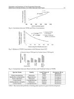
Over the last 50 years, the advance of NC and CNC can be summarized as shown
in Fig. 1.18. NC systems developed in the 1950s were implemented based on hard-
ware and research for replacing the hardware components with software components
got under way. The advancement of electrical technology in the 1970s - 1980s, es-
pecially, meant that the NC system became a CNC system whose functions were
executed by a micro processor. However, the CNC system is a closed system where
a user cannot add customized functions to the CNC system.
NC CNC OAC Soft-NC
∼ 1950
∼ 1980 ∼ 1990 ∼ 2000
Hard-wired Soft-wired PC-based Network-based
Closed system Open H/W Open H/W
and S/W
STEP-based
Fig. 1.18 The change of NC over time
Therefore, during the 1990s, an effort was made to change the closed CNC system
to an Open Architecture Controller (OAC), which is a user-oriented CNC system,
30 1 Introduction to NC Systems
and PC-based open CNC consisting of a PC and VME was introduced as an Open
Architecture Controller. However, the PC-based open CNC did not achieve perfect
openness to fully satisfy the various requirements of a user from the hardware and
software points of view. Consequently, in order to overcome this drawback, it is
expected that future CNC systems will advance to become soft-NC, being open CNC
with an architecture where it is possible to achieve full openness in the software as
well as in the hardware as modularized functions are systematically integrated via
network technology.
Soft-NC is designed to use a PC platform as hardware and the architecture is
designed based on object-oriented technology in order to fulfill openness from the
software viewpoint. Component technology will be applied to the implementation of
function modules and a common soft-bus that is able to support real-time distributed
processing will be applied for integration of components. The soft-NC will have
an architecture that can be applied to robots as well as to machine tools. The main
characteristics of Open CNC are summarized below.
1. Support STEP as a standard data format for machining data for a seamless flow
in the manufacturing process (from CAD to machining).
2. Use soft-bus (e.g. CORBA) to support a real-time distributed processing environ-
ment and to be free to add function modules to CNC.
3. Support component-based API to connect application software modules with the
system platform.
4. Support standard interfaces to communicate with external systems.
5. Support many kinds of field bus to connect sensors with I/O.
6. Support a digital interface between the servo system and the CNC system.
Figure 1.19 shows an example of a CNC to which the concept of Soft-NC is
applied. The CNC shown in Fig. 1.19 is designed based on the concept of modular-
ization, standardization, and distributed processing and uses STEP-compatible part
programs as input. This CNC generates toolpaths by using the code interpreter and
the toolpath generator that are linked via soft-bus and API. After this, the toolpath
is transferred to NCK via a standardized communication environment. During exe-
cution of the above-mentioned procedure, the operation monitoring module and the
adaptive control module, which users develop and add to the CNC, are executed
simultaneously.
In conclusion, the future NC system should be more intelligent and should be
able to carry out complex tasks in a distributed environment with the advancement
of micro processors and communication systems. That is, the future NC system will
advance to be a distributed system that can execute real-time compensation based on
machining status from sensors, communicate and share machining data with other
CNCs, Cell controllers, and MES, and perform tasks by itself.
1.7 Summary 31
System
Config.
Graphic
System
Data
Base
MMI
Code
Interpreter
Task
Scheduler
Toolpath
Generator
Setup
Manager
Online
Inspector
Operation
Monitor
X-axis
Y-axis
Z-axis
Spindle
Driver & Monitor
ISO 14649
Code
Generator
CORBA
Application
Interface
Communication System
NCK/PLC
Operating System
System H/W
Fig. 1.19 Conceptual architecture of an intelligent STEP-compliant CNC
1.7 Summary
The MMI, NCK, PLC, and servo driver are components of which an NC system
consists and, in particular, the NCK is a key component that has an influence upon
the performance of CNC. NCK consists of the interpreter, the interpolator, Acceler-
ation/Deceleration controller, and position controller; the interpreter interprets a part
program and calculates the position to which the axes move. The interpolator calcu-
lates the displacement of axes for every sampling period. The Acceleration/ Deceler-
ation controller plays the role of smoothing axis movement. The position controller
controls the axis movement every sampling period for position control.
The PLC is the module that controls machine behavior, except for servo control,
and is similar to the PLC system of an automated device with respect to sequen-
tially carrying out the sequence program (the so-called ladder program) edited by
the user. However, in respect of exchanging data with the NCK and sharing the sys-
tem resource, the PLC in a CNC system is distinguished from the PLC system of an
automated device.
The MMI plays the role of providing the various user interfaces that are needed
for a user to use NC easily. In order to design the MMI, it is necessary to understand
the cutting mechanism and machine operation mechanism unlike PLC and NCK.
In order to execute the above modules, it is essential to guarantee a real-time envi-
ronment. That is, the key for developing Soft-NC is the scheduling that satisfies the
execution of the software modules in real time. Recently, NC systems have advanced
from being closed systems to being open and distributed systems and the importance
of software will grow.
Chapter 2
Interpreter
The Numerical Control Kernel (NCK) unit is the key component of a CNC system
and consists of a variety of modules that are sequentially executed in a synchronized
schedule. In this chapter the code interpreter will be addressed. This is responsible
for converting the part program and machine instructions into internal commands for
NC. In order to understand the code interpreter the first thing is to understand the part
program that is the input to the interpreter. After this, the structure and the functions
of the code interpreter will be addressed in detail.
2.1 Introduction
The code interpreter is a software module, which translates the part program into
internal commands for moving tools and executing auxiliary functions in a CNC
system.
Figure 2.1 depicts the internal behavior of the CNC system and shows the func-
tions of the Man-Machine Control (MMC), Numerical Control Kernel (NCK), and
Drives (DRV). The part program that a programmer generates based on the shape
of the part, cutting conditions, and tools is entered into CNC via the MMC and the
NCK subsequently generates the control commands for the drivers from the part
program through various stages; calculating the movement path by interpreting the
part program, generating velocity profile and displacement for each axis by interpo-
lation, smoothing the movement by acceleration/deceleration (acc/dec) control, and
generating position control command.
Among these stages, the interpreter could be considered as a simple task for the
conversion of G/M codes to the CNC-understandable internal data structures. How-
ever, the design and implementation of the interpreter is a large and comprehensive
task because programming rules or grammar described in a programming manual
and an operating concept shown in an operation manual should be considered when
developing the interpreter. Therefore, the interpreter is the representative indicator
that shows the design concept and the functional aspect of a CNC and is a big part of
33
34 2 Interpreter
MMC
NC part program
generation
Program loading
Code interpreter
Tool compensation
Motion data
generation
(linear/circular)
Acceleration/
deceleration
Backlash/pitch
error compensation
PID control
Servo drivers/motor
control
NC program
G00 X150 Z300
G54 DO M3 M8
G01 Z
20 F100
Code interpreter
Interpolation
Acceleration/
deceleration
control
Position control
Velocity control
NCK
Work piece
Working profile interpretation
X
Z
X
Z
End point calculation
V
X
V
Z
V
X
V
Z
Z
X
Basic velocity curve generation
Tool movement
Fitted velocity curve generation
DRV
Fig. 2.1 Internal behavior of the CNC system (MMC, NCK, DRV functions)
CNC as it generally spends more than 50% of the total development time to develop
the interpreter.
In this chapter, the format and function of CNC part programs will be brieflyad-
dressed and the architecture, such as the structure of an interpreter, execution proce-
dure, and memory structure, will be addressed. However, because the detailed func-
tion of the CNC and the part program are slightly different for each CNC maker,
the program manual should be referenced to find out the detailed functions of any
particular CNC.
2.2 Part Program
Although the standard exists for generating a CNC part program, sequentially listing
the commands for executing CNC, each CNC maker has, in practice, their own code
system including their own commands. In this section, the common concept will be
described based on the standard code.
2.2 Part Program 35
2.2.1 Program Structure
A part program contains the commands, called blocks, for machining a part and each
block can be defined using the following commands.
• NC commands such as G, M, S, T, H, D, F code and related address
• Call of sub program and displaying message
• Setting variable and conditional program calls
In a part program, the English alphabet, Arabic numbers, and symbols are used
and Fig. 2.2 illustrates the format and elements of a part program.
P123456 ;
Program number
EOB(End of Block) code
Word
Address
N50 G04 P100 ;
N40 Y-20 M03 ;
N30 X15 ;
N20 G01 X50 Y20 F120 S100 ;
N10 G90 ;
N60 M30 ;
Number
Block number
Block
Fig. 2.2 Program format and construction elements
A part program consists of a sequence of NC blocks, each block consists of several
words, and a word is composed of an address and number. The program number is
a number for identifying the particular part program on CNC, where more than one
part program is executed, and is written using a particular address and number in the
heading of a part program. In this book, address P is used but O or # is also used by
some specificCNCmakers.
A block consists of one block number, at least one word, and the EOB, meaning
the End Of Block. The word is the set of characters in a specific order. The word
is the minimum unit for internal processing and commanding the machine tools to
perform a particular behavior. The word consists of an address and a subsequent
number, as below:
36 2 Interpreter
NC word:
address:
value
Y
−20
The address is constructed from one of the alphabetic characters (A Z) or a com-
bination of alphabetic characters. The subsequent number provides the data that is
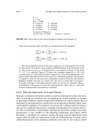
required to execute the behavior related with the address. Table 2.1 summarizes the
addresses that have typically been used and the function that is related with the ad-
dress.
Table 2.1 Typical addresses and associated functions
Function Address Meaning (Example) Unit
Program number P Program identity
no. e.g. P123456
Block number N NC seq.no.
N100
Preparatory function G Mode command
G01
Coordinate (command X, Y, Z / Axis / dir. mm, inch
for translational axis) U, V, W X100 W20
Coordinate (command A, B, C Axis deg
for rotary axis) A30
Feedrate F Feedrate per min. mm/min,
F200 inch/min,
deg/min
Feedrate per rev. mm/rev,
F1 inch/rev,
deg/rev
Spindle speed S S3000 rpm
Tool T Tool number
T12
Auxiliary function M Machine command
M06
Offset Number H, D Offset register no.
H10
Number of repetitions L Iteration no.
of subprogram L5
Radius of circle R Arc rad., corner rad. mm, inch
or arc R3
Chamfer C Chamfer amount mm, inch
C2
Center position of circle I, J, K Circle center coords. mm, inch
Among the addresses described in Table 2.1, the G address, for preparatory func-
tion, and the M address, for auxiliary function, are largely related to the performance
of CNC system. G addresses denote commands for tool movement by moving the
2.2 Part Program 37
translational axes or the rotary axes along the specified path. M addresses denote
commands for controlling the on/off functions in machine tools. G-codes are classi-
fied into two types: one is a modal code and the other is non-modal code. A modal-
type code is effective throughout the following blocks until the modal cancel com-
mand is used. On the other hand, a non-modal-type code is effective within the com-
manded block and automatically canceled by the next block. Modal-type codes are
classified into several groups, called modal groups, with respect to the similarity of
function. In one block, it is prohibited to use more than one G-code that is included
in the same modal group.
The address groups based on the functions of CNC system are summarized in
Table 2.2. As the standard for editing a part program based on these addresses, ISO
6983 has been widely used. However, each CNC maker has their own G&M code
system where maker-specific functions have been added to ISO 6983. Accordingly,
current G&M code systems for generating part programs depend on the CNC system.
If the CNC system is changed, it is almost impossible to reuse the existing part
program. Therefore, in order to create a part program manually, it is necessary to
refer to the programming manual of the particular CNC maker.
According to the level of CNC system, the number of feasible addresses varies
from several tens to several hundreds. Ths means that the more feasible addresses a
CNC system has, so the more advanced the equipment category to which the CNC
system belongs. Further, according to the machine type, the applicable addresses
are defined in different ways. The G-code list and the modal group for a milling
machine and a turning machine are summarized in Appendix A. In the following, the
interpreter is the module that has the function of interpreting the various addresses,
words, and grammar.
38 2 Interpreter
Table 2.2 Summary of address groups based on CNC system functions
Functions Description
Preparatory Codes are used for controlling axis and the CNC system
function prepares the execution of the particular function.
(G-code) (1) movement: command the relative movement between
tool and workpiece.
(2) Setting local coordinate system: specify the origin
and orientation of local coordinate system including
orthogonal coordinate system, the polar coordinate
system, and rotational coordinate system.
(3) Interpolation: command machining various profiles
such as line, arc, helical, spline, etc.
(4) Miscellaneous: commands for tool compensation,
safety check, and skip.
Feed Command the relative speed between tool and
function workpiece for interpolation command.
(F-code)
Spindle Command the spindle speed (RPM).
functions
(S code)
Tool Command tool change and specify the tool compensation.
function
(T-code)
Auxiliary Function commands for the simple control of a machine
function tool including relay/switch on and off as well as axis
(M-code) control.
(1) Coolant: command coolant on or off.
(2) Start/End of a main and sub program: inform the
beginning and end of a part program.
(3) Spindle: command a spindle to rotate in CCW or CW
direction and specify the spindle speed, limit speed and
spindle gear change.
(4) Miscellaneous: Command the change of tool,
workpiece, pallet and rotation of the table/loader.
Utility (1) Subprogram: To simplify the main program,
functions subsidiary program
(2) MACRO register a series of commands as
a particular command and execute various functions by
using the registered command. In a macro, the use of
variables is possible and arithmetic operations between
variables is possible.
(3) Fixed cycle
(i) Turning cycle
Define a series of commands to perform the turning
operations as one command. Outer turning, facing,
grooving, and threading cycle are defined.
(ii) Drilling cycle
Define a series of commands to perform drilling,
tapping, boring, reaming and peck drilling as
drilling cycle.
2.2 Part Program 39
Table 2.2 (continued)
(iii) Milling cycle
Pocket milling, Slot milling. Define a series
of commands to machine profiles that are
frequently machined during pocket milling and
slotting as milling cycles.
(iv) Touch Probe cycle
This command enables the modification of a program
via on-machine inspection before or after machining.
This enables compensation of finishing with
inspection of the machining accuracy.
It is possible to edit the description by inserting words in parentheses within a
block, as below.
N20 G01X0Y0 (MOVE TO ZERO POINT);
✻
comment
The description comment has no influence on the execution of a part program. Be-
cause the description can be shown on the display of the CNC system together with
the block during editing or executing a part program, it is very useful for managing
part programs.
The end of a part program is signalled by the command M02 or M03. By inserting
M02 or M03 at the end of a part program, all modal values are initialized and reset.
Since the commands M02 and M03 are executed last, they can be located anywhere
within the last block.
2.2.2 Main Programs and Subprograms
2.2.2.1 Main program
A part program is classified into a main program and subprograms. Typically, the
CNC system executes a main program. If a main program includes the command
that is used for calling subprograms, the CNC system executes the subprogram indi-
cated. If, during execution of the subprogram, the command for returning to the main
program is called, the main program is then resumed at the block after the command
that called the subprogram, as shown in Fig. 2.3.
2.2.2.2 Subprogram
In the case that there are fixed routine blocks or iterated operation patterns in a part
program, part programming can be made easier if they are stored as a subprogram
in the internal memory of CNC system. It is possible to call the subprogram from a
40 2 Interpreter
Main program Subprogram
✁
✁
✁
✁
✁
✁
✁
✁✕
❅
❅
❅
❅■
block 1
block 2
.
.
.
.
.
.
.
.
.
call subprogram
block n
block n+1
.
.
.
.
.
.
block 1
block 2
.
.
.
.
.
.
.
.
.
.
.
.
.
.
.
.
.
.
.
.
.
.
.
.
return command
Fig. 2.3 Main program and subprogram execution
main program during auto mode of a CNC system. It is also possible to call another
subprogram from within a subprogram.
2.3 Main CNC System Functions
The main functions of a CNC system can be classified into a variety of groups such
as coordinating functions, interpolation functions, compensation functions, safety
functions, and auxiliary utility functions. These will be described in the following
sections.
2.3.1 Coordinate Systems
In CNC systems, a machine coordinate system, a workpiece coordinate system, and
local coordinate systems are defined for convenience when editing a part program
and handling machine tools.
A machine coordinate system is defined by setting a particular point of the ma-
chine tool as the origin of a coordinate system. A workpiece coordinate system is
defined by setting a particular point on the workpiece as the origin so as to make
editing a part program easier. That is, when editing a part program using one partic-
ular workpiece coordinate system, we can edit the part program by defining another
coordinate system based on the workpiece coordinate system. We call this secondary
coordinate system a “local coordinate system”. A workpiece coordinate system is set
by commanding particular G-codes (G54 to G59) and a local coordinate system is
defined by setting an offset (IP) that denotes the displacement of the local coordinate
2.3 Main CNC System Functions 41
system from the origin of the workpiece coordinate system. Based on the origin of
the machine coordinate system, the relationship between each workpiece coordinate
and local coordinate system is illustrated by Fig. 2.4.
Local coordinate system 1
Workpiece coordinate system 1
G54
G55
Origin of machine coordinate system
Local coordinate system 2
Workpiece coordinate system 2
Local coordinate system 6
Workpiece coordinate system 6
Origin of world coordinate system
G59
G56~G58
IP
IP
IP
Fig. 2.4 Machine, workpiece and local coordinate systems
As methods to command displacements of each axis based on the specified coor-
dinate system, there are two modes, absolute programming mode (G90) and incre-
mental programming mode (G91). When absolute programming mode is used, the
end position of each axis is programmed. When incremental programming mode is
used, the relative displacement of each axis is programmed.
Besides orthogonal coordinate systems, it is also possible to use polar coordinate
systems (G15) where a radius component and angle components are used. Figure 2.5
shows a part program using the polar coordinate system and the path that is com-
manded by the part program. To use the polar coordinate system, first a work plane
is selected and then a polar coordinate system is invoked by issuing the command
G15. Thereafter, when using address X and address Y, a radius and an angle, respec-
tively, are commanded.
For part programming, it is possible to use the scaling function and the rotation
function based on the specific coordinate system. The scaling function is used for
scaling down or up the programmed workpiece shape. To command the scaling
function you use the G51 X
Y Z P format in a block, wherein the X, Y, Z ad-
dress denotes the center position for scaling and is given as an absolute value. The
P address is used for the magnitude of the scaling. As G51 is a modal G-code, the
toolpaths in the following blocks are scaled P times up or down with respect to the
point determined by the values above X, Y and Z.
To rotate the specific shape in a part program, the G68
α β
R format is utilized
wherein
α
and
β
denote the center position for rotation and R means a rotational
angle (+R denotes CCW and –R denotes CW). Accordingly, after declaring G68 in
42 2 Interpreter
(Local coordinate system)
Y-axis
X-axis
100 mm
270
o
30
o
150
o
N0100 G17 G90 G15 ; XY plane, absolute coordinate, polar coordinate star
t
N0200 G00 X100 Y30 ; rad. 100mm, ang. 30deg
N0201 X100 Y150 ; rad. 100mm, ang. 150deg
N0202 X100 Y270 ; rad. 100mm, ang. 270deg
N0203 G16 ; Polar coordinates cancel
Fig. 2.5 Polar coordinate system programming
the block, the toolpaths in subsequent blocks are rotated by the angle R with respect
to the point
α
,
β
.
If a workpiece is symmetric with respect to a specific axis, only part of the work-
piece need be programmed, the other parts are created using the G51.1 address that
utilizes a mirror image function. Figure 2.6 shows an example of usage of the mirror
function. The subprogram below is for the path in the upper right side of Fig. 2.6
and the main program below commands the whole path with mirroring of the sub-
program.
The subprogram makes the shape on the upper right. This is invokedin the original
coordinate system in line N20 of the main program. The following command, on
line N30 invokes the mirror function about the symmetry axis X=50. Line N40 then
makes the symmetric shape on the top left. Following this, on line N50 the mirror
function is again invoked to make the Y=50 symmetric axis. The next line, N60,
then calls the subprogram to make the shape on the bottom left. On line N70 the X
symmetry axis is revoked using the G50.1 command and the call of the subprogram
on line N80 makes the shape at the bottom right. Finally, on line N90 the Y symmetry
command is revoked.
2.3.2 Interpolation Functions
There are various interpolation functions that enable machine tools to move the
axes along the specific path for multi-axis machine tools. A CNC system provides
rapid movement, linear interpolation, circular interpolation, helical interpolation, and
spline interpolation functions as interpolation functions.
2.3 Main CNC System Functions 43
Main Program Sub program
P000001; P100001;
N10 G00 G90; N210 G00 G90 X60 Y60;
N30 G51.1 X50; → sym. X=50
N230 Y100;
N40 M98 P100001; N240 X60 Y60;
N250 M99;
N50 G51.1 Y50; → sym. X=50, Y=50
N60 M98 P100001;
N70 G50.1 X0; → reset X
N80 M98 P100001;
N90 G50.1 Y0; → reset Y
N100 M30;
Y
100
N40 N20
60
50
40
100
6050400
N60 N80
X
Fig. 2.6 Example of usage of mirror function
The rapid movement function (G00) is used for commanding the specificaxesto
move rapidly to the programmed position. In the case of an absolute programming
mode (G90), this function makes the axes move to the commanded position from
the current position. In the case of an incremental programming mode (G91), this
function makes the axes move with the commanded incremental value and each axis
moves with the specific feedrate defined in the CNC system. Therefore, it is not
necessary to set an additional feedrate in G00.