Standard Handbook for Mechanical Engineers 2010 Part 8 docx
Bạn đang xem bản rút gọn của tài liệu. Xem và tải ngay bản đầy đủ của tài liệu tại đây (843.67 KB, 70 trang )
8-98 GEARING
Angular straight bevel gears
°
°
͚ °
␥
ϭ
͚ N n ϩ ͚ ͚ °
␥
ϭ
Ϫ ͚ N n Ϫ ° Ϫ ͚
␥
⌫ϭn N ⌫ϭ͚ Ϫ
␥
°
m
m ϭ N
␥
n ⌫ m
N n
x
o
ϭ A
␥
Ϫ a
op
␥
X
o
ϭ
A
⌫Ϫa
oG
⌫
K
Spiral Bevel Gears for 90° Shaft Angle
°
Angular Spiral Bevel Gears
K
° m
° n
ϭ n ⌫
␥
⌫
ϭ m
Fig. 8.3.14
Table 8.3.10 Spiral Bevel Gear Dimensions
n h
k
ϭ
P
d
N h
i
ϭ
P
d
P
d
F ͚
d ϭ
n
P
d
D ϭ
N
P
d
␥
ϭ
Ϫ
n
N
ϭ ° Ϫ
␥
A
O
ϭ
D
⌫
p ϭ
P
d
A
OP
ϭ h
k
Ϫ a
OG
a
OG
ϭ
P
d
ϩ
P
d
N n
b
OP
ϭ h
t
Ϫ a
OP
b
OG
ϭ h
t
Ϫ a
OG
c ϭ h
t
Ϫ h
k
␦
p
ϭ
Ϫ
b
OP
A
O
␦
G
ϭ
Ϫ
b
OG
A
O
␥
O
ϭ
␥
ϩ
␦
G
⌫
O
ϭ⌫ϩ
␦
P
␥
R
ϭ
␥
Ϫ
␦
P
⌫
R
ϭ⌫Ϫ
␦
G
d
O
ϭ d ϩ a
OP
␥
D
O
ϭ D ϩ a
OG
⌫
x
O
ϭ
D
Ϫ a
OP
␥
X
O
ϭ
d
Ϫ a
OG
⌫
t ϭ p Ϫ TTϭ
p
a
OP
Ϫ a
OG
Ϫ
K
P
d
°
Copyright (C) 1999 by The McGraw-Hill Companies, Inc. All rights reserved. Use of
this product is subject to the terms of its License Agreement. Click here to view.
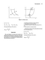
STRENGTH AND DURABILITY 8-103
Geometry factor I
012345678910
Gear ratio D
2
/D
1
N
p
у 50
0.16
0.14
0.12
0.10
0.08
0.06
Number of teeth in pinion
N
p
ϭ 30
N
p
ϭ 24
N
p
ϭ 16
All curves are for the lowest point of single
tooth contact on the pinion
Fig. 8.3.23 I ° Source: ANSI/AGMA 2018-01, with permission.
Geometry factor I
012345678910
Gear ratio D
2
/D
1
N
p
у 50
0.18
0.16
0.14
0.12
0.10
0.08
Number of teeth in pinion
N
p
ϭ 30
N
p
ϭ 24
N
p
ϭ 16
All curves are for the lowest point of single
tooth contact on the pinion
Fig. 8.3.24 I ° Source: ANSI/AGMA 2018-01, with permission.
Copyright (C) 1999 by The McGraw-Hill Companies, Inc. All rights reserved. Use of
this product is subject to the terms of its License Agreement. Click here to view.
8-104 GEARING
Geometry factor J
12
Number of teeth for which geometry factor is desired
0.60
0.55
0.50
0.45
0.40
0.35
0.30
0.25
0.20
0.60
0.55
0.50
0.45
0.40
0.35
0.30
0.25
0.20
Addendum
1.000
2.400
Whole depth
Pinion addendum 1.000
Gear addendum 1.000
20°
0.35
r
T
Generating rack 1 pitch
15 17 20 24 30 35 40 45 50 60 80 125 275 ϱ
Load applied at tip of tooth
1000
Number of teeth
in mating gear
Load applied at highest point
of single tooth contact
170
85
50
35
25
17
Fig. 8.3.25 J ° Source: ANSI/AGMA 2018-01, with permission.
Geometry factor J
0.65
0.60
0.55
0.50
0.45
0.40
0.35
0.30
0.25
0.65
0.60
0.55
0.50
0.45
0.40
0.35
0.30
0.25
12
Number of teeth for which geometry factor is desired
Addendum
1.000
2.350
Whole depth
Pinion addendum 1.000
Gear addendum 1.000
25°
0.27
r
T
Generating rack One Pitch
15 17 20 24 30 35 40 45 50 60 80 125 275 ϱ
Load applied at tip of tooth
1000
Number of teeth
in mating gear
Load applied at highest point
of single tooth contact
170
85
50
35
25
17
Fig. 8.3.26 J ° Source: ANSI/AGMA 2018-01, with permission.
Copyright (C) 1999 by The McGraw-Hill Companies, Inc. All rights reserved. Use of
this product is subject to the terms of its License Agreement. Click here to view.
STRENGTH AND DURABILITY 8-105
Geometry factor J
0.70
0.60
0.50
0.40
0.30
0°
Tooth height
Generating rack
20°
0.157
P
nd
r
T
ϭ
2.157
P
nd
1.0
P
nd
Add.
5° 10° 15° 20° 25° 30° 35°
500
150
60
Number of teeth
30
20
Helix angle
⌿
Standard addendum, finishing hob
Fig. 8.3.27 J °
Source: ANSI/AGMA 2018-01, with permission.
Geometry factor J
0.70
0.60
0.50
0.40
0.30
0°
Tooth height
Generating rack
20°
0.4276
P
nd
r
T
ϭ
2.355
P
nd
1.0
P
nd
Add.
5° 10° 15° 20° 25° 30° 35°
500
150
60
Number of teeth
30
20
Helix angle
⌿
Standard addendum, full fillet hob
Fig. 8.3.28 J °
Source: ANSI/AGMA 2018-01, with permission.
Copyright (C) 1999 by The McGraw-Hill Companies, Inc. All rights reserved. Use of
this product is subject to the terms of its License Agreement. Click here to view.
8-106 GEARING
Geometry factor J
0.80
0.70
0.60
0.50
0.40
0°
Tooth height
Generating rack
25°
0.27
P
nd
r
T
ϭ
2.35
P
nd
1.0
P
nd
Add.
5° 10° 15° 20° 25° 30° 35°
500
150
60
Number of teeth
30
20
Helix angle
Standard addendum, full fillet hob
Fig. 8.3.29 J °
Source: ANSI/AGMA 2018-01, with permission.
Modifying factor
0° 5° 10° 15° 20°
Helix angle,
25° 30°
500
1.05
1.00
0.95
0.90
0.85
30
20
35°
Number of teeth in mating element
150
75
50
Fig. 8.3.30 J °
J Source: ANSI/AGMA 2018-01, with permission.
Copyright (C) 1999 by The McGraw-Hill Companies, Inc. All rights reserved. Use of
this product is subject to the terms of its License Agreement. Click here to view.
Modifying factor
0° 5° 10° 15° 20°
Helix angle
25° 30°
500
150
75
50
1.05
1.00
0.95
0.90
0.85
30
20
35°
Number of teeth in mating element
Fig. 8.3.31 J °
J Source: ANSI/AGMA 6010-E88, with permission.
Table 8.3.15 Allowable Contact Stress Number s
ac
for Steel Gears
s
ac
Table 8.3.16 Allowable Contact Stress Number s
ac
for Iron and Bronze Gears
s
ac
8-107
Copyright (C) 1999 by The McGraw-Hill Companies, Inc. All rights reserved. Use of
this product is subject to the terms of its License Agreement. Click here to view.
8-110 GEARING
Stress cycle factor
Z
N
10
2
Number of load cycles
N
4.0
3.0
2.0
1.1
1.0
0.9
0.8
0.7
0.6
5.0
0.5
Nitrided
Z
N
ϭ 1.249
N
Ϫ0.0138
Z
N
ϭ 2.466
N
Ϫ0.056
NOTE: The choice of
Z
N
in the shaded zone
is influenced by:
Lubrication regime
Failure criteria
Smoothness of operation required
Pitchline velocity
Gear material cleanliness
Material ductility and fracture toughness
Residual stress
Z
N
ϭ 1.4488
N
Ϫ0.023
10
3
10
4
10
5
10
6
10
7
10
8
10
9
10
10
Fig. 8.3.35 Z
N
Source: ANSI/AGMA 2001-C95, with permission.
Hardness ratio factor
C
H
Caculated hardness ratio,
H
BP
H
BG
1.14
1.12
1.10
1.08
1.06
1.04
1.02
1.00
0
2 4 6 8 10 12 14 16 18 20
Single reduction gear ratio
H
BG
ϭ gear Brinell hardness number
H
BP
ϭ pinion Brinell hardness number
1.7
1.6
1.5
1.4
1.3
1.2
When
Use
C
H
ϭ 1
Ͻ 1.2,
H
BP
H
BG
Fig. 8.3.36 C
H
Source: ANSI/AGMA 2001-C95, with permission.
Copyright (C) 1999 by The McGraw-Hill Companies, Inc. All rights reserved. Use of
this product is subject to the terms of its License Agreement. Click here to view.
Allowable bending stress number
S
at
,1000lb/in
2
50
40
30
20
10
150
200 250 300
Brinell hardness
H
B
350 400 450
Metallurgical and quality
control procedures required
Grade 2
S
at
ϭ 102
H
B
ϩ 16 400
Grade 1
S
at
ϭ 77.3
H
B
ϩ 12,800
Fig. 8.3.39 s
at
Source: ANSI/AGMA 2001-C95,
with permission.
Allowable bending stress number
S
at
,
1000lb/in
2
80
70
60
50
40
30
20
250
275 300 325
Core hardness
H
B
350
Metallurgical and quality control procedures required
Grade 2
S
at
ϭ 108.6
H
B
ϩ 15 890
Grade 1
S
at
ϭ 82.3
H
B
ϩ 12 150
Fig. 8.3.40 s
at
Source: ANSI/AGMA 2001-C95, with permission.
Allowable bending stress number
S
at
,
1000lb/in
2
70
60
50
40
30
250
275 300 325
Core hardness
H
B
350
Metallurgical and quality control procedures required
Grade 3 – 2.5% chrome
S
at
ϭ 105.2
H
B
ϩ 29 280
Grade 2 – 2.5% chrome
S
at
ϭ 105.2
H
B
ϩ 22 280
Grade 1 – 2.5% chrome
S
at
ϭ 105.2
H
B
ϩ 9280
Grade 2 – nitralloy
S
at
ϭ 1113.8
H
B
ϩ 16 650
Grade 1 – nitralloy
S
at
ϭ 86.2
H
B
ϩ 12 730
Fig. 8.3.41 s
at
Source: ANSI/AGMA 2001-C95, with
permission.
8-112
Copyright (C) 1999 by The McGraw-Hill Companies, Inc. All rights reserved. Use of
this product is subject to the terms of its License Agreement. Click here to view.
Table 8.3.20 Viscosity Ranges for AGMA Lubricants
a b c
°
a
d
d
d
° °
e
f e
° °
a
b
c
d
Comp
e
° ° ° °
f
Table 8.3.21 AGMA Lubricant Number Guidelines for Open Gearing (Continuous Method of Application)
a,b
c
° °
Ϫ
d
d
e
f
a
b
c
d
e
° ° ° °
f
° ° ° °
Table 8.3.22 AGMA Lubricant Number Guidelines for Open Gearing Intermittent
Applications
a,b,c
ge
d
° °
f
Ϫ
a
b
c
d
e
f
g
8-114
Copyright (C) 1999 by The McGraw-Hill Companies, Inc. All rights reserved. Use of
this product is subject to the terms of its License Agreement. Click here to view.
GEAR LUBRICATION 8-115
Table 8.3.23 AGMA Lubricant Number Guidelines for Enclosed
Helical, Herringbone, Straight Bevel, Spiral Bevel, and Spur Gear
Drives
a
a d e
° °
f g
b c
Ϫ Ϫ Ϫ ϩ
Ϫ ϩ
h
h
a
b
c
d
e
f
g
° °
h
Table 8.3.24 Typical Gear Lubricants
°
Oils
Ϫ
Ϫ
Ϫ
Ϫ
Ϫ
Greases
Ϫ
Ϫ
Ϫ
Ϫ
Copyright (C) 1999 by The McGraw-Hill Companies, Inc. All rights reserved. Use of
this product is subject to the terms of its License Agreement. Click here to view.
8-116 FLUID FILM BEARINGS
Table 8.3.25 Solid Oil Additives
Temperature
Lubricant type range, °F Source Identification Remarks
Colloidal graphite Up to 1,000 Acheson Colloids Co. SLA 1275 Good load capacity, excellent temperature
resistance
Colloidal MoS
2
Up to 750 Acheson Colloids Co. SLA 1286 Good antiwear
Colloidal Teflon Up to 575 Acheson Colloids Co. SLA 1612 Low coefficient of friction
they will provide long service life if the plastic chosen is correct for the
application. Plastics manufacturers and their publications can be con-
sulted for guidance. Alternatively, many plastic gear materials can be
molded with internal solid lubricants, such as MoS
2
, Teflon, and graphite.
GEAR INSPECTION AND QUALITY CONTROL
Gear performance is not only related to the design, but also depends
upon obtaining the specified quality. Details of gear inspection and
control of subtle problems relating to quality are given in Michalec,
‘‘Precision Gearing,’’ Chap. 11.
COMPUTER MODELING AND CALCULATIONS
A feature of the latest AGMA rating standards is that the graphs, in-
cluding those presentedhere, areaccompanied byequations whichallow
application of computer-aided design. Gear design equations and
strength and durability rating equations have been computer modeled by
many gear manufacturers, users, and university researchers. Numerous
software programs, including integrated CAD/CAM, are available from
these places, and from computer system suppliers and specialty soft-
ware houses. It is not necessary for gear designers, purchasers, and
fabricators to create their own computer programs.
With regard to gear tooth strength and durability ratings, many cus-
tom gear house designers and fabricators offer their own computer
modeling which incorporates modifications of AGMA formulas based
upon experiences from a wide range of applications.
The following organizations offer software programs for design and
gear ratings according to methods outlined in AGMA publications:
Fairfield Manufacturing Company Gear Software; Geartech Software,
Inc.; PC Gears; Universal Technical Systems, Inc. For details and current
listings, refer to AGMA’s latest ‘‘Catalog of Technical Publications.’’
8.4 FLUID FILM BEARINGS
by Vittorio (Rino) Castelli
R
EFERENCES
: ‘‘General Conference on Lubrication and Lubricants,’’ ASME.
Fuller, ‘‘Theory and Practice of Lubrication for Engineers,’’ 2d ed., Wiley.
Booser, ‘‘Handbook of Lubrication, Theory and Design,’’ vol. 2, CRC Press.
Barwell, ‘‘Bearing Systems, Principles and Practice,’’ Oxford Univ. Press. Cam-
eron, ‘‘Principles of Lubrication,’’ Longmans Greene. ‘‘Proceedings,’’ Second
International Symposium on Gas Lubrication, ASME. Gross, ‘‘Fluid-Film Lubri-
cation,’’ Wiley. Gunter, ‘‘Dynamic Stability of Rotor-Bearing Systems,’’ NASA
SP-113, Government Printing Office.
Plain bearings, according to their function, may be
Journal bearings, cylindrical, carrying a rotating shaft and a radial
load
Thrust bearings, the function of which is to prevent axial motion of a
rotating shaft
Guide bearings, to guide a machine element in its translationalmotion,
usually without rotation of the element
In exceptional cases of design, or with a complete
failure of lubrica-
tion,
a bearing may run dry. The coefficient of friction is then between
0.25 and 0.40, depending on the materials of the rubbing surfaces. With
the
bearing barely greasy, or when the bearing is well lubricated but the
speed of rotation is very slow, boundary lubrication takes place. The
coefficient of friction may vary from 0.08 to 0.14. This condition occurs
also in any bearing when the shaft is starting from rest if the bearing is
not equipped with an oil lift.
Semifluid, or mixed, lubrication exists between the journal and bearing
when the conditions are not such as to form a load-carrying fluid film
and thus separate the surfaces. Semifluid lubrication takes place at com-
paratively low speed, with intermittent or oscillating motion, heavy
load, insufficient oil supply to the bearing (wick or waste-lubrication,
drop-feed lubrication). Semifluid lubrication may also exist in thrust
bearings with fixed parallel-thrust collars, in guide bearings of machine
tools, in bearings with copious lubrication where the shaft is bent or the
bearing is misaligned, or where the bearing surface is interrupted by
improperly arranged oil grooves. The coefficient of friction in such
bearings may range from 0.02 to 0.08 (Fuller, Mixed Friction Condi-
tions in Lubrication, Lubrication Eng., 1954).
Fluid or
complete lubrication, when the rubbing surfaces are com-
pletely separated by a fluid film, provides the lowest friction losses and
prevents wear. A certain amount of oil must be fed to the oil film in
order to compensate for end leakage and maintain its carrying capacity.
Such lubrication can be provided under pressure from a pump or gravity
tank, by automatic lubricating devices in self-contained bearings (oil
rings or oil disks), or by submersion in an oil bath (thrust bearings for
vertical shafts).
Notation
R ϭ radius of bearing, length
r ϭ radius of journal, length
c ϭ mr ϭ R Ϫ r ϭ radial clearance, length
W ϭ bearing load, force
ϭ viscosity ϭ force ϫ time/length
2
Z ϭ viscosity, centipoise (cP); 1 cP ϭ 1.45 ϫ 10
Ϫ7
lb и s/in
2
(0.001 N и s/m
2
)

ϭ angle between load and entering edge of oil film
ϭ coefficient for side leakage of oil
ϭ kinematic viscosity ϭ
/
, length
2
/time
R
e
ϭ Reynolds number ϭ umr/
P
a
ϭ absolute ambient pressure, force/area
P ϭ W/(ld) ϭ unit pressure, lb/in
2
N ϭ speed of journal, r/min
m ϭ clearance ratio (diametral clearance/diameter)
F ϭ friction force, force
A ϭ operating characteristic of plain cylindrical bearing
P Јϭalternate operating characteristic of plain cylindrical bearing
h
0
ϭ minimum film thickness, length
ϭeccentricity ratio, or ratio of eccentricity to radial clearance
e ϭ eccentricity ϭ distance between journal and bearing centers,
length
f ϭ coefficient of friction
f Јϭfriction factor ϭ F/(
rl
u
2
)
l ϭ length of bearing, length
d ϭ 2r ϭ diameter of journal, length
Copyright (C) 1999 by The McGraw-Hill Companies, Inc. All rights reserved. Use of
this product is subject to the terms of its License Agreement. Click here to view.
INCOMPRESSIBLE AND COMPRESSIBLE LUBRICATION 8-117
K
f
ϭ friction factor of plain cylindrical bearing
t
w
ϭ temperature of bearing wall
t
0
ϭ temperature of air
t
1
ϭ temperature of oil film
u ϭ surface speed, length/time
ϭ angular velocity, rad/time
ϭ mass density, mass/length
3
⌳ϭbearing compressibility parameter ϭ 6
r
2
/(P
a
c
2
)
INCOMPRESSIBLE AND COMPRESSIBLE
LUBRICATION
Depending on the fluid employed and the pressure regime, the fluid
density may or may not vary appreciably from the ambient value in the
load-carrying film. Typically, oils, water, and liquid metals can be con-
sidered incompressible, while gases exhibit compressibility effects even
at modest loads. The difference comes from the fact that, in incom-
pressible lubricants, fluid flow rates are linearly proportional to pressure
differences, whereas for compressible lubricants the mass flow rates are
proportional to the difference of some power of the pressure. This is
because the pressure affects the fluid density. The bearing behavior is
somewhat dissimilar. In incompressible lubrication, gage pressures can
be used and the value of the ambient pressure has no effect on the
load-carrying capacity, which is linearly related to viscosity and speed.
This is not true in compressible lubrication, where the value of ambient
pressure has a direct effect on the load-carrying capacity which, in turn,
increases with viscosity and speed, but only up to a limit dependent on
the bearing geometry. In what follows, incompressible lubrication is
treated first and compressible lubrication second.
Incompressible (Plain Cylindrical Journal
Bearings)
Fluid lubrication in plain cylindrical bearings depends on the viscosity
of the lubricant, the speed of the bearing components, the geometry of
the film, and possible external sources of pressurized lubricant. The oil
is entrained by the journal into the film by the action of the viscosity
which, if the passage is convergent, causes the creation of a pressure
field, resulting in a force sufficient to float the journal and carry the load
applied to it.
The
minimum film thickness h
0
determines the closest approach of the
journal and bearing surfaces (Fig. 8.4.1). The allowable closest ap-
proach depends on the finish of these surfaces and on the rigidity of the
journal and bearing structures. In practice, h
0
ϭ 0.00075 in (0.019 mm)
is common in electric motors and generators of medium speed, with
Fig. 8.4.1 Journal bearing with perfect lubrication.
steel shafts in babbitted bearings; h
0
ϭ 0.003 in (0.076 mm) to 0.005 in
(0.127 mm) for large steel shafts running at high speed in babbitted
bearings (turbogenerators, fans), with pressure oil-supply for lubrica-
tion; h
0
ϭ 0.0001 in (0.0025 mm) to 0.0002 in (0.005 mm) in automo-
tive and aviation engines, with very fine finish of the surfaces.
Figure 8.4.2 gives the relationship between and the load-carrying
coefficient A for a plain cylindrical journal. The operating characteristic
of the bearing is
A ϭ (132/
)(1,000m)
2
[P/(ZN)]
In Fig. 8.4.1,

is the angle between the direction of the load W and
the entering edge of the load-carrying oil film, in degrees. The entering
edge is at the place where the hydrodynamic pressure is equal or nearly
equal to the atmospheric pressure and may be at the location of the
Fig. 8.4.2 Eccentricity ratio for a plain cylindrical journal.
oil-distributing groove B, or at the end of the machined recess pocket as
at AA. For
complete bearings, i.e., when the inner surface of thebearing is
not interrupted by grooves,

may be taken as 90°. The reason for this
assumption is the fact that, where the film diverges, the bearing pump-
ing action tends to generate negative pressure, which liquids cannot
sustain. The film
cavitates; i.e., it breaks up in regions of fluid inter-
mixed with either air or fluid vapor, while the pressure does not deviate
substantially from ambient. For a 120° bearing with a central load,

may be taken as 60°.
The coefficient
corrects for side leakage. There is a loss of load-
carrying capacity caused by the drop in the hydrodynamic pressure p in
the oil film from the midsection of the bearing toward its ends; p ϭ 0at
the ends. The value of
depends on the length-diameter ratio l/d and ,
the eccentricity ratio. Values of
are given in Fig. 8.4.3.
Fig. 8.4.3
E
XAMPLE
1. A generator bearing, 6 in diam by 9 in long, carries a vertical
downward load of 8,650 lb; N ϭ 720 r/min. The diametral clearance of the
bearing is 0.012 in; the bearing is split on its horizontal diameter, and the lower
half is relieved 40° down on each side, for oil distribution along journal; the
bearing arc is therefore 100°; with the load vertical,

ϭ 50°; bearing temper-
ature 160°F. The absolute viscosity of the oil in the film is 12 centipoises
(medium turbine oil). P ϭ W/ld ϭ 160 lb/in
2
;
ϭ 12 ϫ 1.45 ϫ 10
Ϫ7
ϭ 17.4 ϫ
10
Ϫ7
lb и s/in
2
. The solution is one of trial and error. By using Fig. 8.4.3 in con-
junction with Fig. 8.4.2, only a few trials are necessary to obtain the answer. As a
first trial assume ϭ0.85. For an l/d ratio of 1.5 in Fig. 8.4.3,
, the end-leakage
factor, will be 0.77. Compute A using this value of
. m ϭ 0.012/6 ϭ 0.002.
A ϭ
132
0.77
(2)
2
160
12 ϫ 720
ϭ 12.7
Copyright (C) 1999 by The McGraw-Hill Companies, Inc. All rights reserved. Use of
this product is subject to the terms of its License Agreement. Click here to view.
8-118 FLUID FILM BEARINGS
Enter Fig. 8.4.2 with this value of a and at

ϭ 50°, and find that ϭ0.9. This
value is larger than the initial assumption for . As a second trial, ϭ0.88. Then
ϭ 0.8, A ϭ 12.2, and ϭ0.89. This is a sufficiently close check. The minimum
film thickness is h
0
ϭ mr(1 Ϫ) ϭ 0.002 ϫ 3 ϫ 0.12 ϭ 0.0007 in (0.01778 mm).
For severe operating conditions the value of A may exceed 18, the
limit of Fig. 8.4.2. For complete journal bearings under extreme operat-
ing conditions, Fig. 8.4.4 should be used. The ordinate is PЈ, defined as
shown. The curves are drawn for various values of l/d instead of values
of

as in Fig. 8.4.2. Values of may thus be obtained directly (Denni-
son, Film-Lubrication Theory and Engine-Bearing Design, Trans.
ASME, 58, 1936).
Fig. 8.4.4 Load-carrying parameter in terms of eccentricity.
E
XAMPLE
2. A 360° journal bearing 2
1
⁄
2
in diam and 3
7
⁄
8
in long carries a
steady load of 3,875 lb. Speed N ϭ 500 r/min; diametral clearance, 0.0064 in;
average viscosity of the oil in the film, 23.4 centipoises (SAE 20 light motor oil at
105°F). P ϭ 3,875/(2.5 ϫ 3.875) ϭ 400 lb/in
2
. Value of m ϭ 0.0064/2.5 ϭ
0.00256. Value of l/d ϭ 1.55. First, attempt to use Figs. 8.4.2 and 8.4.3 in this
solution. Assume eccentricity ratio is 0.9. Then, in Fig. 8.4.3, with l/d ϭ 1.55,
value of
is determined as 0.8. A is calculated as 37. This is completely off scale
in Fig. 8.4.2. Consider instead Fig. 8.4.4. Value of PЈ is computed as
PЈϭ6.9(2.56)
2
400
23.4 ϫ 500
ϭ 1.54
In Fig. 8.4.4, enter the curves with PЈϭ1.54, and move left to intersect the curve
for l/d ϭ 1.5. Drop downward to read a value for 1/(1 Ϫ) of 16. Then
1
⁄
16
ϭ
1 Ϫ, or the eccentricity ratio ϭ
15
⁄
16
, or 0.94. The minimum film thickness,
as in Example 1 ϭ h
0
ϭ mr(1 Ϫ), or
h
0
ϭ 0.00256 ϫ 1.25(1 Ϫ 0.94) ϭ 0.0002 in (0.0051 mm)
Allowable mean bearing pressures
in bearings with fluid film lubrica-
tion are given in Table 8.4.1. If the load maintains the same magnitude
and direction when the journal is at rest (heavily loaded shafts, heavy
gears), the mean bearing pressure should be somewhat less than when
bearings are loaded only when running.
For internal-combustion-engine bearing design, Etchells and Under-
wood (Mach. Des., Sept. 1942) list the following maximum design
pressures for bearing alloys, pounds per square inch of projected area:
lead-base babbitt (75 to 85 percent lead, 4 to 10 percent tin, 9 to 15
percent antimony) 600 to 800; tin-base babbitt (0.35 to 0.6 percent lead,
86 to 90 percent tin, 4 to 9 percent antimony, 4 to 6 percent copper) 800
to 1,000; cadmium-base alloy (0.4 to 0.75 percent copper, 97 percent
cadmium, 1 to 1.5 percent nickel, 0.5 to 1.0 percent silver) 1,200 to
1,500; copper-lead alloy (45 percent lead, 55 percent copper) 2,000 to
3,000; copper-lead (25 percent lead, 3 percent tin, 72 percent copper)
3,000 to 4,000; silver (0.5 to 1.0 percent lead on surface, 99 percent
silver) 5,000 up. The above pressures are based on fatigue life of 500 h
at 300°F bearing temperature, and a bearing metal thickness 0.01 to
0.015 in for lead-, tin-, and cadmium-base metals and 0.25 in for copper,
lead, and silver. At lower temperatures the life will be greatly extended.
Much higher pressures are encountered in rolling element bearings,
such as ball and roller bearings, and gears. In these situations, the for-
mation of fluid films capable of preventing contact between surface
asperities is aided by the increase of viscosity with pressure, as exhib-
ited by most lubricating oils. The relation is typically exponential,
ϭ
0
e
␣
p
, where
␣
is the so-called pressure coefficient of viscosity.
Length-diameter ratios are usually chosen between l/d ϭ 1 and l/d ϭ
2, although many engine bearings are designed with l/d ϭ 0.5, or even
less. In shorter bearings, the carrying capacity of the oil film is greatly
impaired by the effect of side leakage. Longer bearings are used to
restrain the shaft from vibration, as in line shafts, or to position the shaft
accurately, as in machine tools. In power machines, the tendency is
toward shorter bearings. Typical values are as follows: turbogenerators,
0.8 to 1.5; gasoline and diesel engines for main and crankpin bearings,
0.4 to 1.0, with most values between 0.5 and 0.8; generators and motors,
1.5 to 2.0; ordinary shafting, heavy, with fixed bearings, 2 to 3; light,
with self-aligning bearings, 3 to 4; machine-tool bearings, 2 to 4;
railroad journal bearings, 1.2 to 1.8.
For the
clearance between journal and bearing see Fits in Sec. 8. Me-
dium fits may be used for journals running at speeds under 600 r/min,
and free fits for speeds over 600 r/min. Kingsbury suggests for these
journals a diametral clearance ϭ 0.002 ϩ 0.001d in. In journals running
at high speed, diametral clearance ϭ 0.002d should be used in order to
lower the friction losses in the bearing. All units are in inches. The most
satisfactory clearance should, of course, be based on a complete bearing
analysis which includes both load-carrying capacity and heat generation
due to friction. For example, a bearing designed to run at the extremely
high speed of 50,000 r/min uses a diametral clearance of 0.0025 in for
a journal with 0.8-in diameter, giving a clearance ratio, clearance/
diameter, of 0.00316.
Table 8.4.1 Current Practice in Mean Bearing Pressures
Permissible Permissible
pressure, lb/in
2
, pressure, lb/in
2
,
Type of bearing of projected area Type of bearing of projected area
Diesel engines, main bearings 800–1,500
Crankpin 1,000–2,000
Wrist pin 1,800–2,000
Electric motor bearings 100– 200
Marine diesel engines, main bearings 400– 600
Crankpin 1,000–1,400
Marine line-shaft bearings 25– 35
Steam engines, main bearings 150– 500
Crankpin 800–1,500
Crosshead pin 1,000–1,800
Flywheel bearings 200– 250
Marine steam engine, main bearings 275– 500
Crankpin 400– 600
Steam turbines and reduction gears 100– 220
Automotive gasoline engines, main bearings 500–1,000
Crankpin 1,500–2,500
Air compressors, main bearings 120– 240
Crankpin 240– 400
Crosshead pin 400– 800
Aircraft engine crankpin 700–2,000
Centrifugal pumps 80– 100
Generators, low or medium speed 90– 140
Roll-neck bearings 1,500–2,500
Locomotive crankpins 1,500–1,900
Railway-car axle bearings 300– 350
Miscellaneous ordinary bearings 80– 150
Light line shaft 15– 25
Heavy line shaft 100– 150
Copyright (C) 1999 by The McGraw-Hill Companies, Inc. All rights reserved. Use of
this product is subject to the terms of its License Agreement. Click here to view.
INCOMPRESSIBLE AND COMPRESSIBLE LUBRICATION 8-119
For high-speed internal-combustion-engine bearings using forced-
feed lubrication, medium fits are used. Federal-Mogul recommends the
following diametral clearances in inches per inch of shaft diameter for
insert-type bearings: tin-base and high-lead babbitts, 0.0005; cadmium-
silver-copper, 0.0008; copper-lead, 0.001.
The dependence of the
coefficient of friction for journal bearings on the
bearing clearance, lubricant viscosity, rotational speed, and loading
pressure, as reported by McKee and others, is shown in Sec. 3. A plot of
the coefficient of friction against the parameter ZN/P is a convenient
method for showing this relationship. ZN/P is a parameter based on
mixed units. Z is the viscosity in centipoise, N is r/min, P is the mean
pressure on the bearing due to the load, pounds per square inch of
projected area, and m is the clearance ratio. Values of ZN/P greater than
about 30 indicate fluid film conditions in the bearings. If the viscosity of
the lubricant becomes lower or if there is a reduction in rotational speed
or an increase in load, the value of ZN/P will become smaller until the
coefficient of friction reaches a minimum value. Any further reduction
in ZN/P will produce breakdown of the oil film, marking the transition
from fluid film lubrication with complete separation of the moving
surfaces to semifluid or mixed lubrication, where there is partial con-
tact. As soon as semifluid conditions are initiated, there will be a sharp
increase in the coefficient of friction. The critical value of ZN/P, where
this transition takes place, will be lowest for a rigid bearing and shaft
with finely finished surfaces.
Figure 8.4.5 shows a generalization of the relationship between the
coefficient of friction for a journal bearing and the parameter ZN/P,
Fig. 8.4.5 Various zones of possible lubrication for a journal bearing.
indicating the various possible lubrication regimes that may be ex-
pected. For optimum design, a value of ZN/P somewhere between 30
and 300 would be recommended, but, in any case, the determination of
minimum film thickness h
0
should be the deciding parameter. For ex-
tremely large values of ZN/P, resulting from high speeds and low loads,
Fig. 8.4.6 Variation of the friction factor of a bearing with eccentricity ratio.
whirl instability may be developed. (See material on gas-lubricated
bearings in this section.) With large values of ZN/P and a lubricant
having a low kinematic viscosity, turbulent conditions may develop in
the bearing clearance.
The friction force in plain journal bearings may be estimated by the
use of the expression F ϭ K
f
Nrl/m, where
is in lbиs/in
2
units. The
value of K
f
depends upon the magnitude of and the type of bearing.
Figure 8.4.6 shows values of K
f
for a complete bearing, a 150° partial
bearing, and a 120° partial bearing, assuming that the clearance space is
at all times filled with lubricant. Note that F is the friction force at the
surface of the bearing. Consequently, the friction torque is obtained by
multiplying F by the bearing radius.
E
XAMPLE
3. As an illustration of the use of Fig. 8.4.6, determine the friction
force in the bearing of Example 2. This is a complete journal bearing 2
1
⁄
2
-in diam
by 3
7
⁄
8
in. The value of was determined as 0.94. From Fig. 8.4.6, K
f
ϭ 2.8. Then
F ϭ
2.8 ϫ 23.4 ϫ 1.45 ϫ 10
Ϫ7
ϫ 500 ϫ 1.25 ϫ 3.875
0.00256
ϭ 8.97 lb (4.08 kg)
The coefficient of friction F/W ϭ 8.97/3875 ϭ 0.00231. The mechanical loss in
the bearing is FV/33,000 hp, where V is the peripheral velocity of the journal,
ft/min.
Friction hp ϭ (8.97 ϫ 500 ϫ
ϫ 2.5)/(33,000 ϫ 12)
ϭ 0.089 hp (66.37 W)
Departure from laminarity in the fluid film of a journal bearing will
increase the friction loss. Figure 8.4.7 (Smith and Fuller, Journal Bear-
ing Operation at Super-laminar Speeds, Trans. ASME, 78, 1956) shows
test results for such bearings, expressed in terms of a Reynolds number
for the fluid film, R
e
ϭ umr/
. Laminar conditions hold up to an R
e
of
about 1,000. Friction may be calculated for laminar flow by using Fig.
8.4.6 or the left branch of the curve in Fig. 8.4.7, where fЈϭ2/R
e
, and
which applies to low values of the eccentricity ratio (K
f
ϭ 0.66). The
values from Fig. 8.4.7 may be converted to friction torque T by the use
of the expression T ϭ fЈ
u
2
r
2
l, where
is the mass density of the
lubricant. In Fig. 8.4.7, a transition region spans values of the Reynolds
number from 1,000 to 1,600. Here, two types of flow instability can
occur. Usually, the first is due to
Taylor vortices which are wrapped in
Fig. 8.4.7 Friction f Ј as a function of the Reynolds number for an unloaded
journal bearing with l/d ϭ 1. (Smith and Fuller.)
regular circumferential structures, each of which occupies the entire
clearance. The onset of this phenomenon takes place at a value of the
Reynolds number exceeding the threshold R
e
ϭ 41.1(r/c)
1/2
. The second
instability is due to turbulence, occurring at R
e
Ͼ 2,000.
E
XAMPLE
4. A journal bearing is 4.5 in diameter by 4.5 in long. Speed
22,000 r/min. mr ϭ 0.002 in. Viscosity
, 1 cP (water) ϭ 1.45 ϫ 10
Ϫ7
lbиs/in
2
;
mass density
ϭ 62.4/1,728 ϫ 386 ϭ 9.35 ϫ 10
Ϫ5
lbиs
2
/in
4
; v ϭ
/
ϭ 1.45 ϫ
10
Ϫ7
/9.35 ϫ 10
Ϫ5
ϭ 0.155 ϫ 10
Ϫ2
in
2
/s; u ϭ 22,000 ϫ 2
ϫ 2.25/60 ϭ 5,180
in/s; R
e
ϭ 5,180 ϫ 0.002/0.155 ϫ 10
Ϫ2
ϭ 6,680. This would indicate turbulence
in the film. Value of fЈ is then 0.078/6,680
0.43
ϭ 0.078/44.2 ϭ 1.765 ϫ 10
Ϫ3
.
Friction torque T ϭ 1.765 ϫ 10
Ϫ3
ϫ
ϫ 9.35 ϫ 10
Ϫ5
ϫ 5,180
2
ϫ 2.25
2
ϫ 4.5,
T ϭ 317.5 inи lb. Friction horsepower ϭ 2
TN/12 ϫ 33,000 ϭ 2
ϫ 317.5 ϫ
22,000/12 ϫ 33,000, FHP ϭ 111 (82.77 kW).
Copyright (C) 1999 by The McGraw-Hill Companies, Inc. All rights reserved. Use of
this product is subject to the terms of its License Agreement. Click here to view.
8-120 FLUID FILM BEARINGS
In self-contained bearings (electric motor, line shaft, etc.) without
external oil or water cooling, the
heat dissipation is equal to the heat
generated by friction in the bearing.
The heat dissipated from the outside bearing wall to the surrounding
air is governed by the laws of heat transfer Q ϭ hS(t
w
Ϫ t
0
), where S is
the surface area from which the heat is convected, Q is the rate of energy
flow; t
w
and t
0
are the temperatures of the wall and ambient air, respec-
tively; and h is the heat convection coefficient, which has values from
2.2 Btu/(hиft
2
и°F) for still air to 6.5 Btu/(hи ft
2
и°F) for air moving at
500 ft/min. Calculations of heat loss are extremely important due to the
strong temperature dependence of the viscosity of most oils.
The temperature of the oil film will be higher than the temperature of
the bearing wall. Typical ranges of values according to Karelitz (Trans.
ASME, 64, 1942), Pearce (Trans. ASME, 62, 1940), and Needs (Trans.
ASME, 68, 1948) for self-contained bearings with oil bath, oil ring, and
waste-packed lubrication are shown in Fig. 8.4.8.
Fig. 8.4.8 Temperature rise of the film.
E
XAMPLE
5. The frictional loss for the generator bearing of Example 1, com-
puted by the method outlined in Example 3, is 0.925 hp with ϭ0.88, K
f
ϭ 1.6,
and F ϭ 27 lb. Operating in moving air the heat dissipated by the bearing housing
will be L ϭ 6.5S(t
w
Ϫ t
0
). Since this is a self-contained bearing, the heat dissi-
pated is also equal to the heat generated by friction in the oil film, or L ϭ 0.925 ϫ
2,545 ϭ 2,355 Btu/h. With S ϭ 25 ϫ 6 ϫ 9/144 ϭ 9.4 ft
2
, t
w
ϭ t
0
ϭ 2,355/6.5 ϫ
9.4 ϭ 38.5°F. This is the temperature rise of the bearing wall above the ambient
room temperature. For an 80°F room, the wall temperature of the bearing would
be about 118°F. In Fig. 8.4.8 an oil-ring bearing in moving air with a temperature
rise of wall over ambient of 38°F should have a film temperature 50°F higher than
that of the wall. The film temperature on the basis of Fig. 8.4.8 will then be 80 ϩ
38 ϩ 50, or 168°F. This is close enough to the value of the film temperature of
160°F from Example 1, with which the friction loss in the bearing was computed,
to indicate that this bearing can operate without the need for external cooling.
To predict the operating temperature of a self-contained bearing, the
cut-and-try method shown above may be used. First, an oil-film tem-
perature is assumed. Viscosity and friction losses are calculated. Then
the temperature rise of the wall over ambient is computed so as to
dissipate to the atmosphere an amount of heat equal to the friction loss.
Lastly from Fig. 8.4.8 the corresponding oil-film temperature is esti-
mated and compared to the value that was originally assumed. A few
adjustments of the assumed film temperature will produce satisfactory
agreement and indicate the leveling-off temperature of the bearing.
Self-contained bearings have been built with diameters of 3, 8, and 24 in
(7.62, 20.32, and 60.96 cm) to operate at shaft speeds of 3,600, 1,000,
and 200 r/min, respectively. These designs indicate a rough limit for
bearings with no external cooling. The highest bearing temperature per-
missible with normal lubricants is about 210°F (100°C).
The temperature of automotive-type bearings is held within safe
limits by using a
pressure-feed oil supply. Sufficient lubricant is forced
through the bearing to act as a coolant and prevent overheating. One
widely used practice is to place a circumferential groove at the center of
the bearing to which the oil supply is fed. This is effective as far as
cooling is concerned but has the disadvantage of interrupting the active
length of the bearing and lowering its l/d ratio (see Fig. 8.4.9). The axial
flow through each side of the bearing is given by
Q
1
ϭ
⌬Pm
3
r
4
6
b
ͩ
1 ϩ
3
2
2
ͪ
where b is the effective axial length of the half bearing and ⌬ P is the
difference between the oil pressure in the circumferential groove and
Fig. 8.4.9 Bearing with central circumferential groove.
the pressure at the ends of the bearing. The value of the last term in this
equation will vary from 1.0 for a concentric shaft and bearing indicated
by ϭ0 to a value of 2.5 for the extreme case of the shaft touching the
bearing wall, indicated when ϭ1. Most of the heat caused by friction
in the bearing is carried away by the circulating oil. Permissible temper-
ature rises for this type of bearing may range from 15 to 50°F(8to
28°C). In extreme cases a rise of 100°F (55°C) can be tolerated for
high-strength bearing materials. The lower values of temperature rise
usually indicate needlessly large oil flow. Such a condition will result in
an excessive friction loss in the bearing.
E
XAMPLE
6. The bearing of Examples 2 and 3 is lubricated by a circumfer-
ential groove with an oil supply pressure of 30 lb/in
2
and, as before, ϭ0.94,
m ϭ 0.0026, and
ϭ 23.4 ϫ 1.45 ϫ 10
Ϫ7
lbиs/in
2
. Length b is about 1.93 in.
Q
1
flow out one side ϭ
30 ϫ 0.0026
3
ϫ 1.25
4
ϫ
6 ϫ 23.4 ϫ 1.45 ϫ 10
Ϫ7
ϫ 1.93
ϫ [1 ϩ 3/2(0.94)
2
] ϭ 0.240 in
3
/s (3.93 cm
3
/s)
Total flow (two sides) ϭ 0.48 in
3
/s ϭ 53 lb/h for sp gr ϭ 0.85. The friction loss
from Example 3 ϭ 0.089 hp ϭ 226 Btu/h. With a specific heat of 0.5 Btu/(lbи°F)
and assuming that all the friction energy is given up to the oil in the form of heat,
the temperature rise ⌬ t ϭ 226/0.5 ϫ 53 ϭ 8.5°F (4.72°C).
A definite minimum rate of oil feed is required to maintain a fluid film
in journal bearings. This makes no allowance for the additional flow
that may be needed to cool the bearings. However, many industrial
bearings run at relatively low speeds with light loads and, as a conse-
quence, additional oil flow to provide cooling is not necessary. But if a
fluid film is desired, a definite minimum amount of lubricant is re-
quired. If the volume of lubricant fed to the bearing is less than this
minimum requirement, there will not be a complete fluid film in the
bearing. Friction will rise, wear will become greater, and the satisfac-
tory service life of such a bearing will be reduced. This minimum lubri-
cant supply can be evaluated by using the equation
Q
M
ϭ K
M
urml
where Q
M
is the flow rate and K
M
is approximately 0.006.
Fig. 8.4.10 Siphon wick. Fig. 8.4.11 Bottom wick.
Copyright (C) 1999 by The McGraw-Hill Companies, Inc. All rights reserved. Use of
this product is subject to the terms of its License Agreement. Click here to view.
INCOMPRESSIBLE AND COMPRESSIBLE LUBRICATION 8-121
E
XAMPLE
7. The minimum feed rate for a journal bearing 2
1
⁄
8
-in diam by
2
1
⁄
8
in long will be determined. Diametral clearance is 0.0045 in; speed,
1,230 r/min; load, 40 lb/in
2
based on projected area. u ϭ 1,230 ϫ
ϫ 2.125 ϭ
10,220 in/min, r ϭ 1.062 in, m ϭ 0.0045/2.125 ϭ 0.00212, l ϭ 2.125 in. Substi-
tuting,
Q
M
ϭ 0.006 ϫ 10,220 ϫ 1.062 ϫ 0.00212 ϫ 2.125
ϭ 0.28 in
3
/min
(Fuller and Sternlicht, Preliminary Investigation of Minimum Lubricant Require-
ments of Journal Bearings, Trans. ASME, 78, 1956.)
Many bearings are supplied with oil at low rates of feed by felts, wicks,
and drop-feed oilers. Wicks can supply substantial rates of feed if they
are properly designed. The two basic types of wick feed are siphon
wicks, as shown in Fig. 8.4.10, and bottom wicks, as shown in Fig.
Fig. 8.4.12 Oil delivery with siphon wick (Fig. 8.4.10).
8.4.11. Data on oil delivery for these wicks are shown in Figs. 8.4.12
and 8.4.13. The data, from the American Felt Co., are for SAE Fl felts,
based on a cross-sectional area of 0.1 in
2
. The flow rate is indicated in
drops per minute. One drop equals 0.0026 in
3
or 0.043 cm
3
.
E
XAMPLE
8. If it is desired to deliver 12.5 drops/min to a journal bearing, and
if the viscosity of the oil is 212 s Saybolt Universal at 70°F, and if L, Fig. 8.4.10, is
5 in, what size of round wick would be required? From Fig. 8.4.12, for the stated
conditions the delivery rate would be 0.9 drop/min for an area of 0.1 in
2
. If 12.5
drops/min is needed, this would mean an area of 12.5 divided by 0.9 and multi-
plied by 0.1, or 1.4 in
2
. For a round wick this would mean a diameter of 1
3
⁄
8
in
(3.49 cm).
If a
bottom wick is considered with L ϭ 4 in, Fig. 8.4.11, then in Fig. 8.4.13 the
delivery rate using the same oil would be 1.6 drops/min; and if 12.5 drops/min is
required, the area would be 12.5 divided by 1.6 and multiplied by 0.1, or 0.78 in
2
.
This would mean a bottom wick of 1 in diam if it is round (2.54 cm).
When journal bearings are started, stopped, or reversed, or whenever
conditions are such that the operating value of ZN/P falls below the
critical value for that bearing, the oil film will be ruptured and metal-to-
metal contact will increase friction and cause wear. This condition can
be eliminated by using a
hydrostatic oil lift. High-pressure oil is intro-
duced to the area between the bottom of the journal and the bearing
(Fig. 8.4.14). If the pressure and quantity of flow are great enough, the
shaft, whether it is rotating or not, will be raised and supported by an oil
film. Neglecting axial flow, which is small, the flow up one side is
Q
1
ϭ
Wrm
3
A
in
2
/s
and the inlet pressure required, P
o
ϭ
Q
1
B/(br
2
m
3
), where b is the axial
length of the high-pressure recess. Values of A and B are dimensionless
factors which represent geometric effects and are given in the following
table as a function of :
0 0.1 0.2 0.3 0.4 0.5 0.6 0.7 0.75 0.8 0.85 0.9
A 24.0 28.1 33.8 41.6 53.3 72.0 105 173 237 360 613 1,320
B 18.9 23.2 29.0 38.2 52.7 77.9 128 246 344 634 1,260 3,360
0.91 0.92 0.93 0.94 0.95 0.96 0.97 0.98 0.99
A 1,620 2,070 2,620 3,530 5,040 7,800 13,700 30,600 121,000
B 4,340 5,810 8,040 11,800 18,400 32,100 65,300 179,000 348,000
Fig. 8.4.13 Oil delivery with bottom wick (Fig. 8.4.11).
Current practice is to make the total area of the high-pressure recess
in a bearing 2
1
⁄
2
to 5 percent of the projected area ld of the bearing. It is
generally desirable to use a check valve in the supply line to the oil lift
so that, when the journal builds up a hydrodynamic oil-film pressure,
reverse flow of oil in the supply line will be prevented.
Fig. 8.4.14 Diagram of oil lift.
E
XAMPLE
9. A 4,000-in-diam journal rests in a bearing of 4.012-in-diam.
SAE 30 oil at 100°F (105 cP) is supplied under pressure to a groove at the lowest
point in the bearing. Length of bearing, 6 in, length of groove, 3 in, load on
bearing, 3,600 lb. What inlet pressure and oil flow are needed to raise the journal
0.004 in?
h
0
ϭ mr(1 Ϫ)
0.004 ϭ 0.006(1 Ϫ)
ϭ0.333
From the table, A ϭ 44.5, B ϭ 42.
Q
1
ϭ
3,600 ϫ 2
44.5 ϫ 105 ϫ 1.45 ϫ 10
Ϫ7
(0.003)
3
ϭ 0.287 in
3
/s, one side (4.70 cm
3
/s)
Flow from both sides ϭ (0.287 ϫ 2) ϫ
60
⁄
231
ϭ 0.149 gal/min (0.564 l/min).
Oil supply pressure is
P
o
ϭ
105 ϫ 1.45 ϫ 10
Ϫ7
ϫ 0.287 ϫ 42
3 ϫ 4
ϫ
1
0.003
3
ϭ 566 lb/in
2
Copyright (C) 1999 by The McGraw-Hill Companies, Inc. All rights reserved. Use of
this product is subject to the terms of its License Agreement. Click here to view.
8-122 FLUID FILM BEARINGS
Fig. 8.4.15 Load-carrying capacity and flow for journal bearings (Loeb). Lengths in inches.
An adjustable constant-volume pump or a spur-gear pump with a capacity of
about 1,000 lb/in
2
(6.894 kN/m
2
) should be used to allow for pressure that may be
built up in the line before the journal begins to rise.
Other configurations for hydrostatically lubricated journal bearings
are shown in Fig. 8.4.15. These were obtained by means of electric
analog solutions (Loeb, Determination of Flow, Film Thickness and
Load-Carrying Capacity of Hydrostatic Bearings through the Use of the
Electric Analog Field Plotter, Trans. ASLE, 1, 1958). The data from Fig.
8.4.15 are exact for a uniform film thickness corresponding to ϭ0 but
may be used with discretion for other values of .
Multiple recesses are used in externally pressurized bearings in order
to provide local
stiffness. This term indicates that the bearing resists
shaft motions in any direction, and it is achieved by properly arranging
the feeding network according to a strategy called
compensation. Three
main types are employed: orifice (and its variant, inherent), capillary,
and fixed flow rates. In the first two, the idea is to insert a hydraulic
resistance in each of the recess feeding lines and to use a single pump to
feed all recesses. The flow rate q through orifices varies with the square
root of the pressure drop ⌬p
q ϰ
√
⌬p
while for capillary tubes the relation is linear:
q ϭ
⌬pd
4
64 l
1
The general rule of thumb in designing orifices or capillary restrictors is
to generate a pressure drop approximately equal to that taking place
through the bearing, i.e., from the recesses to the ambient. The recess
geometry and distribution, on the other hand, are designed so that W ϭ
0.5p
recess
DL. Thus, the pump supply pressure is 4 times the average
bearing pressure. The bearing stiffness is usually equal to K ϭ
0.5p
recess
DL/c.
The third method of compensation consists of forcing the same
amount of flow to reach each recess regardless of clearance distribution.
This can be achieved either by using separate pumps for each recess or
by using a hydraulic device called a flow divider. With recess distribu-
tions as indicated above, the pump pressure need only be double the
average bearing pressure; thus, this method of compensation leads to
half the power dissipation of the other two. It is commonly used in large
machinery, where power consumption must be limited. The polar axis
bearings of the 200-in Hale telescope on Mount Palomar were the first
large-scale demonstration of this technique. The azimuth axis thrust
bearing of the 270-ft-diameter Goldstone radio telescope is probably the
largest example of this type of bearing.
ELEMENTS OF JOURNAL BEARINGS
Typical dimensions of solid and split bronze bushings are given in Table
8.4.2.
Bronze bushings made from hard-drawn sheets and rolled into cylin-
drical shape are made with a wall thickness of only
1
⁄
32
in for bearings up
to
1
⁄
2
in diam and with a wall thickness of
1
⁄
16
in for bearings from 1 in
diam up. The wall thickness of these bearings depends chiefly upon the
strength of the material which supports them. Bushings of this type are
pressed into place, and the bearing surface is finished by burnishing
with a slightly tapered bar to a mirror finish. The allowable bearing
pressures may exceed those of cast bronze shown in Table 8.4.1 by10 to
20 percent.
Babbitt linings in larger bearings are generally employed in thickness
of
1
⁄
8
in or over and must be provided with sufficient anchorage in the
Table 8.4.2 Wall Thickness of Bronze Bushings, in
Diam of journal, in
1
⁄
4
1
⁄
4
–
1
⁄
2
1
⁄
2
–1 1–1
1
⁄
2
1
1
⁄
2
–2
1
⁄
2
2
1
⁄
2
–4 4–5
1
⁄
2
Solid bushing, normal
1
⁄
16
3
⁄
32
1
⁄
8
3
⁄
16
1
⁄
4
3
⁄
8
1
⁄
2
Split bushing, normal
3
⁄
32
1
⁄
8
5
⁄
32
7
⁄
32
5
⁄
16
15
⁄
32
5
⁄
8
Solid bushing, thin
1
⁄
16
3
⁄
32
3
⁄
32
1
⁄
8
3
⁄
16
1
⁄
4
3
⁄
8
Split bushing, thin
1
⁄
16
3
⁄
32
1
⁄
8
3
⁄
16
1
⁄
4
3
⁄
8
1
⁄
2
Copyright (C) 1999 by The McGraw-Hill Companies, Inc. All rights reserved. Use of
this product is subject to the terms of its License Agreement. Click here to view.
ELEMENTS OF JOURNAL BEARINGS 8-123
supporting shell. The anchors take the form of dovetailed grooves or
holes drilled in the shell and counterbored from the outside.
Improved conditions are obtained by sweating or bonding the babbitt
to the shell by tinning the latter, using potassium chlorate as flux. Tin-
base babbitts and other low-strength materials evidence some yielding
when subjected to heavy pressures. This tendency may be alleviated by
the use of a thinner layer of the bearing material, fused either to a bronze
or to a steel shell. This improves the fatigue life of the bearing material.
Standard bearing inserts of this type are available in tin-base babbitts,
high-lead babbitts, cadmium alloys, and copper-lead mixtures in diame-
ters up to about 6 in (15.24 cm) (Fig. 8.4.16). A few materials can be
obtained in sizes up to 8 in (20.32 cm). Some types are available with
flanges or with other special features. The bearing lining may vary from
about 0.001 in (0.025 mm) to 0.1 in (2.5 mm) in thickness depending
upon the size of the bearing.
Fig. 8.4.16 Bearing insert.
Figure 8.4.17 shows the principal types of bonded babbitt linings.
Figure 8.4.17a is for normal operating conditions. Figure 8.4.17b is for
more severe operating conditions.
Fig. 8.4.17
General practice for the thickness of babbitt lining and shells is as fol-
lows: Fig. 8.4.18, b ϭ
1
⁄
32
d ϩ
1
⁄
8
in, S ϭ 0.18d for bronze or steel ϭ 0.2d
for cast iron; Fig. 8.4.18a, t ϭ b/2 ϩ
1
⁄
16
in, W ϭ 1.8t, W
1
ϭ 2.2t.
Solid bronze or steel bushings, when pressed into the bearing hous-
ing, must be finished after pressing in. Light press fits and securing by
Fig. 8.4.18
setscrews or keys are preferable to heavy press fits and no keying, since
heavy pressure, especially in thin-walled bushings, will set up stresses
which will release themselves if bearings should run hot in service and
will result in closing in on the journal and scoring when cooling.
Uniform Load Distribution Misalignment between journal and
bearing should never be so great as to cause metallic contact. The max-
imum allowable inclination
␣
of the shaft to the bearing is given by
tan
␣
ϭ md/l.
Whenever the deflection angle of the bearing installation is greater
than
␣
, either the bearing length should be reduced or, if that is not
feasible, the bearing should be mounted on a spherical seat to permit
self-alignment.
Oil grooves are of two kinds, axial and circumferential; the former
distribute the oil lengthwise in the bearing; the latter distribute it around
the shaft at the oil hole, and also collect and return oil which would
Fig. 8.4.19
otherwise be forced out at the ends of the
bearing. Grooves have often been put into
bearings indiscriminatingly, with the re-
sult that they scrape off the oil and in-
terrupt the film.
In Fig. 8.4.19, W is the resultant force
or load, pounds, on the bearing or journal.
The radial ordinates P
1
, to the dotted
curve, show the pressures, lb/in
2
, of the
journal on the oil film due to the load
when there is no axial groove, while the
ordinates P
2
, to the solid curve, show the pressures with an incorrectly
located groove. Since there is no oil pressure near the groove, the per-
missible load W must be reduced or the film will be ruptured.
Groove dimensions (Fig. 8.4.20) are given by the followingrelations:
a ϭ
1
⁄
3
wall thickness; W
o
ϭ 2.5a; W
d
ϭ 3a; c ϭ 0.5W
d
; f ϭ
1
⁄
16
in to
0.5W
d
.
In order to maintain the oil film,
the axial distributing groove should be
placed in the unloaded sector
of the bearing. The location of grooves in a
variety of cases is shown in Figs. 8.4.21 to 8.4.30.
Fig. 8.4.20 Lubrication and drainage grooves.
Horizontal Bearings, Rotational Motion
D
IRECTION OF
L
OAD
K
NOWN AND
C
ONSTANT
Load downward or inside the lower 60° segment as in the case of
ring-oiling bearings (Fig. 8.4.21).
Load at an angle more than 45° to the vertical centerline (Fig. 8.4.22).
In force- or drop-feed oiling, the oil inlet may be anywhere within the
no-load sector (Fig. 8.4.23).
Oil can be introduced through the center of the revolving shaft (Fig.
8.4.24).
Fig. 8.4.21
Copyright (C) 1999 by The McGraw-Hill Companies, Inc. All rights reserved. Use of
this product is subject to the terms of its License Agreement. Click here to view.
THRUST BEARINGS 8-125
Fig. 8.4.32a, b, and c. The seal material that is pressed against the
rotating shaft is typically made of synthetic rubber, which is satisfactory
for temperatures as high as about 250°F (121°C). Figure 8.4.32a shows
the seal material pressed against the shaft by a series of flexible fingers
Fig. 8.4.32 Seals for oil and grease retention.
or leaf springs. In Fig. 8.4.32b a helical garter spring provides the grip-
ping force. In Fig. 8.4.32c the rubber acts as its own spring.
Types of bearings are shown in Figs. 8.4.33 to 8.4.38. They include the
principal methods of lubrication and types of construction.
Oiless bearings is the accepted term for self-lubricating bearings con-
taining lubricants in solid or liquid form in their material. Graphite,
molybdenum disulfide, and Teflon are used as solid lubricants in one
group, and another group consists of porous structures (wood, metal),
containing oil, grease, or wax.
Fig. 8.4.33 Ring-oiled bearing solid bushing.
Fig. 8.4.34 Rigid ring-oiling pillow block. (Link Belt Co.)
Fig. 8.4.35 Split bearing with one chain. Main crankshaft bearing; vertical oil
engine.
Graphite-lubricated bearings
(bridge bearings, sheaves, trolleywheels,
high-temperature applications) consist generally of cast bearing bronze
as a supporting structure containing various overlapping designs of
grooves which are filled with graphite. The graphite is mixed with a
binder, and the plastic mass is pressed into the cavities to the hardness of
a lead pencil; 45 percent of the bearing area may be graphite.
Porous-metal bearings, compressed from metal powders and sintered,
contain up to 35 percent of liquid lubricant. See ASTM B202-45T for
sintered bronze and iron bearings, and also Army and Navy Specifica-
tion AN-B-7G. The porous metal generally consists of a 90-10 copper-
Fig. 8.4.36 Crankshaft main bearing. Horizontal engine with drop-feed lubri-
cation.
tin bronze with 1
1
⁄
2
percent graphite. These bearings do not require oil
grooves since capillarity distributes the oil and maintains an oil film. If
additional lubrication from an oil well should be provided, oil will be
absorbed through the porous wall as required. For high temperatures
where oil will carburize, a higher percentage of graphite (6 to 15 per-
cent) is used.
Fig. 8.4.37
Porous-metal bearings are used where plain metal bearings are im-
practical because of lack of space, cost, or inaccessibility for lubrica-
tion, as in automotive generators and motors, hand power tools, vacuum
cleaner motors, and the like.
Fig. 8.4.38
THRUST BEARINGS
At low speeds, shaft shoulders or collars bear against flat bearing rings.
The lubrication may be semifluid, and the friction is comparatively
high.
For hardened-steel collars on bronze rings, with intermittent service,
pressures up to 2,000 lb/in
2
(13,790 kN/m
2
) are permissible; for contin-
uous low-speed operation, 1,500 lb/in
2
(10,341 kN/m
2
); for steel collars
on babbitted rings, 200 lb/in
2
(1,378.8 kN/m
2
). In multicollar thrust
bearings, the values are reduced considerably because of the difficulty
in distributing the load evenly between the several collars.
Copyright (C) 1999 by The McGraw-Hill Companies, Inc. All rights reserved. Use of
this product is subject to the terms of its License Agreement. Click here to view.
8-126 FLUID FILM BEARINGS
The performance of the bearing thrust rings is much improved by the
introduction of
grooves with tapered lands as shown in Fig. 8.4.39. The
lands extend on either side of the groove. The taper angle of the lands is
very slight, so that a pressure oil film is formed between the bearing ring
Fig. 8.4.39 Thrust collar with grooves fitted with tapered lands.
and the collar of the shaft. It is generally known that slightly tapered
radial grooves will develop a hydrodynamic load-carrying film, when
formed in the manner of Fig. 8.4.39. The taper angle should be on the
order of 0.5°. Alternatively, a shallow recessed area that is a couple of
Fig. 8.4.40 Kingsbury
thrust bearing with six shoes.
film thicknesses deep can be used in
place of the taper.
For high speeds or where low friction
losses and a low wear rate are essential,
pivoted segmental thrust bearings are used
(Kingsbury thrust bearing, or Michell
bearing in Europe). The bearing members
in this type are tiltable shoes which rest
on hard steel buttons mounted on the
bearing housing. The shoes are free to
form automatically a wedge-shaped oil
film between the shoe surface and the
collar of the shaft (Figs. 8.4.40 to 8.4.42).
The
minimum oil-film thickness h
0
, in, between the shoe and the collar,
at the trailing edge of the shoe, is approximately
h
0
ϭ 0.26
√
ul/P
avg
where
is the absolute viscosity; u is the velocity of the collar, on the
mean diam; l is the length of a shoe, at the mean diam of the collar, in
the direction of sliding motion; P
avg
is the average load on the shoes. As
indicated in Fig. 8.4.40, b ϭ l, approximately. The standard thrust bear-
ings have six shoes. Load-carrying capacities of Kingsbury thrust bear-
ings are given in Table 8.4.3.
Fig. 8.4.41 Left half of six-shoe self-aligning equalizing horizontal thrust bear-
ing for load in either axial direction.
The coefficient of friction in Kingsbury thrust bearings, referred to
the mean diameter of the shoes, is approximately f ϭ 11.7h
0
/l, where h
0
is computed as shown above. Figures 8.4.41 and 8.4.42 show typical
pivoted segmental thrust bearings. They usually embody a system of
Fig. 8.4.42 Half section of mounting for vertical thrust bearing.
rocking levers which are used for alignment and equalization of load on
the several shoes (Fig. 8.4.43).
Thrust may be carried on a hydrostatic step bearing as shown sche-
matically in Fig. 8.4.44, where high-pressure oil at P
o
is supplied at the
Fig. 8.4.43 Kingsbury thrust bearings. (Developed cylindrical sections.)
center of the bearing from an external pump. The lubricant flows radi-
ally outward through the annulus of depth h
0
and escapes at the periph-
ery of the shaft at some pressure P
1
which is usually at atmospheric
pressure. An oil film will be present whether the shaft rotates or not.
Friction in these bearings can be made to approach zero, depending
Fig. 8.4.44 Hydrostatic step bearing.
Copyright (C) 1999 by The McGraw-Hill Companies, Inc. All rights reserved. Use of
this product is subject to the terms of its License Agreement. Click here to view.
8-128 FLUID FILM BEARINGS
Fig. 8.4.46 Load-carrying capacity and flow for several flat thrust bearings (Loeb). Lengths in inches.
Naturally, if the change in pressure within the bearing clearance is
small compared to ambient pressure, the compressibility effect will be
likewise small, and lubrication equations based on liquids may be used.
A
compressibility parameter ⌳ indicates the extent of this action. For
hydrodynamic journal bearings it has the form ⌳ϭ6
/(P
a
m
2
). For
Fig. 8.4.47
Fig. 8.4.48
Fig. 8.4.49
values of ⌳ less than one, the previous equations of this section for
journal bearings may be used. For values of ⌳ greater than one, com-
pressibility effects are included through the use of Figs. 8.4.51 to 8.4.54.
(Data from Elrod and Burgdorfer, Proceedings First International Sym-
posium on Gas-lubricated Bearings, 1959, and Raimondi, Trans. ASLE,
vol. IV, 1961.)
Fig. 8.4.50
E
XAMPLE
11. Determine the minimum film thickness for a journal bearing
0.5 in (1.27 cm) diameter by 0.5 in long. Ambient pressure 14.7 lb/in
2
abs (101.34
kN/m
2
abs). Speed 12,000 r/min. Load 0.4 lb (0.88 kg). Diametral clearance
0.0005 in (0.0127 mm). Lubricant, air at 100°F and 14.7 lb/in
2
abs (2.68 ϫ
10
Ϫ9
lbиs/in
2
from Fig. 8.4.55). m ϭ 0.0005/0.5 ϭ 0.001 in/in.
ϭ 12,000 ϫ
2
/60 ϭ 1,256 rad/s, ⌳ϭ(6 ϫ 2.68 ϫ 10
Ϫ9
ϫ 1,256)/14.7 ϫ 0.001
2
ϭ 1.37, and
W/(dlP
a
) ϭ 0.4/0.5 ϫ 0.5 ϫ 14.7 ϭ 0.109. Then, in Fig. 8.4.53 (l/d ϭ 1), we
find that ϭ0.22, and the minimum film thickness h
0
ϭ 0.00025(1 Ϫ 0.22) ϭ
0.000195 in (0.00495 mm).
Gas-lubricated journal bearings should be checked for whirl stability.
Figure 8.4.56 is applicable with sufficient accuracy to bearings where
l/d is equal to or greater than one. It is used in conjunction with Fig.
8.4.51 for l/d ϭϱ. The stability parameter is
*
1
which, for a bearing
having only gravity loading, has the value
*
1
ϭ
√
mr/g.
E
XAMPLE
12. To determine whether the bearing of Example 11 is stable at
the running speed of 12,000 r/min, we compute
*
1
as 1,256
√
0.00025/386ϭ
1.015. The value of eccentricity ratio
0
for l/d ϭϱis computed from Fig. 8.4.51
Copyright (C) 1999 by The McGraw-Hill Companies, Inc. All rights reserved. Use of
this product is subject to the terms of its License Agreement. Click here to view.
GAS-LUBRICATED BEARINGS 8-131
Fig. 8.4.60 Filmatic bearing. (Courtesy Cincinnati Milacron Corp.)
should not be made flat for gas operation but should have a crowned
contour (see Fig. 8.4.63). (Gross, ‘‘Gas Film Lubrication,’’ Wiley.) An
approximate value for the crown is to make
␦
ϭ
3
⁄
4
h
0
. The tilting-pad
bearing design is probably the most common gas bearing presently in
existence. Every hard-disk computer memory since the early 1960s has
had its read-write heads supported by self-acting tilting-pad sliders.
Hundreds of millions of such units, called flying heads, have been man-
ufactured to date. Some designs employ the crown geometry while,
Fig. 8.4.61 Cross-sectional view, spring-mounted pivot assembly. (Courtesy of
The Franklin Institute Research Labs.)
most commonly, heads with flat multiple sliders with straight ramps in
their forward sections are used. The reason for the multiple thin sliders
is the achievement of maximum damping possible. The typical mini-
mum film heights have decreased steadily through the years from 1
m
Fig. 8.4.62 Bending-dominated segments foil bearing.
(40 millionths of an inch) 25 years ago to less than 0.2
m (8 millionths
of an inch) currently (1995). This trend is driven by the achievement of
the higher and higher recording densities possible at lower flying
heights. Design of these devices is done rather precisely from first prin-
ciples by means of special simulation programs. At these low clear-
ances, allowance must be made for the finiteness of the
molecular mean
free path,
which represents the mean distance that a gas molecule must
travel between collisions. This effect manifests itself in a lowering of
viscosity and wall shear resistance.
Fig. 8.4.63 Schematic of tilting-pad shoe, showing crown height
␦
.
Gas-lubricated hydrostatic bearings, unlike liquid-lubricated bear-
ings, cannot be designed on the basis of fixed flow rate. They are de-
signed instead to have a pressure loss produced by an
orifice restrictor in
the supply line. Such throttling enables the bearing to have load-carry-
ing capacity and stiffness. For maximum stiffness the pressure drop in
the orifice may be about one-half of the manifold supply pressure. For a
circular thrust bearing with a single circular orifice, the load-carrying
capacity is given with sufficient accuracy by the equation previously
used for liquids (see Fig. 8.4.44). W ϭ (P
R
Ϫ P
a
/2)[R
2
Ϫ R
2
0
/ln (R/R
0
)],
where P
R
is the recess pressure, lb/in
2
abs. The flow volume, however,
is given by Q
0
ϭ
h
3
0
/[6
ln (R/R
0
)](P
2
0
Ϫ P
2
1
)/2P
0
. Q
0
and P
0
refer to
recess conditions, and Q
1
and P
1
refer to ambient conditions. Pressures
are absolute.
E
XAMPLE
13. A circular thrust bearing 6 in (15.24 cm) diameter with a recess
2 in (5.08 cm) diameter has a film thickness of h
0
ϭ 0.0015 in (0.0381 mm). P
0
ϭ
30 lb/in
2
gage or 44.7 lb/in
2
abs (308.16 kN/m
2
). P
1
is room pressure, 14.7 lb/in
2
abs (101.34 kN/m
2
abs). Depth of recess is 0.02 in. Applied load is 375 lb. Q
0
ϭ
(
ϫ 0.0015
3
)/(6 ϫ 2.68 ϫ 10
Ϫ9
ln 3)(44.7
2
Ϫ 14.7
2
)/(2 ϫ 44.7), Q
0
ϭ 12.3 in
3
/s
(201.6 cm
3
/s) at recess pressure. Converted to free air, Q
1
ϭ Q
0
(P
0
/P
1
) with
isothermal expansion, Q
1
ϭ 12.3(44.7/14.7) ϭ 37.4 in
3
/s (612.87 cm
3
/s), or Q
1
ϭ
37.4 ϫ 60 ϭ 2,244 in
3
/min (36.77 L/min). Actual measured flow ϭ 2,440 in
3
/min
(39.98 L/min).
Externally pressurized gas bearings are not as easily designed as
liquid-lubricated ones. Whenever a volume larger than approximately
that of the film is present between the restrictor and the film, a phenom-
enon known as
air hammer or pneumatic instability can take place.
Therefore, in practical terms, recesses cannot be used and orifice re-
strictors must be obtained by the smallest flow cross-section at the very
entrance to the film; this area is equal to the perimeter of the inlet holes
multiplied by the local height of the film. This technique is called
inher-
ent compensation.
Unfortunately, as one can readily see, the area of the
restrictors is smaller where the film is smaller; thus, the stiffness is
lower than that obtainable by incompressible lubrication. Design data
are available in Sec. 5 of Gross’s book (see References).
Copyright (C) 1999 by The McGraw-Hill Companies, Inc. All rights reserved. Use of
this product is subject to the terms of its License Agreement. Click here to view.
8.5 BEARINGS WITH ROLLING CONTACT
by Michael W. Washo
R
EFERENCES
: Anti-Friction Bearing Manufacturers Association, Inc. (AFBMA),
Method of Evaluating Load Ratings. American National Standards Institute
(ANSI), Load Ratings for Ball and Roller Bearings. AFBMA, ‘‘Mounting Ball
and Roller Bearings.’’ Tedric A. Harris, ‘‘Rolling Bearing Analysis.’’
COMPONENTS AND SPECIFICATIONS
Rolling-contact bearings are designed to support and locate rotating
shafts or parts in machines. They transfer loads between rotating and
stationary members and permit relatively free rotation with a minimum
of friction. They consist of
rolling elements (balls or rollers) between an
outer and inner ring. Cages are used to space the rolling elements from
each other. Figure 8.5.1 illustrates the common terminology used in
describing rolling-contact bearings.
Fig. 8.5.1 Radial contact bearing terminology.
Rings
The inner and outer rings of a rolling-contact bearing are
normally made of SAE 52100 steel, hardened to Rockwell C 60 to 67.
The rolling-element raceways are accurately ground in the rings to a
very fine finish (16
in or less).
Rings are available for special purposes in such materials as stainless
steel, ceramics, and plastic. These materials are used in applications
where corrosion is a problem.
Rolling Elements Normally the rolling elements, balls or rollers, are
made of the same material and finished like the rings. Other rolling-ele-
ment materials, such as stainless steel, ceramics, Monel, and plastics,
are used in conjunction with various ring materials where corrosion is a
factor.
Cages Cages, sometimes called separators or retainers, are used to
space the rolling elements from each other. Cages are furnished in a
wide variety of materials and construction. Pressed-steel cages, riveted
or clinched and filled nylon, are most common. Solid machined cages
are used where greater strength or higher speeds are required. They are
fabricated from bronze or phenolic-type materials. At high speeds, the
phenolic type operates more quietly with a minimum amount of friction.
Bearings without cages are referred to as full-complement.
A wide variety of rolling-contact bearings are normally manufactured
to standard boundary dimensions (bore, outside diameter, width) and
tolerances which have been standardized by the AFBMA. All bearing
manufacturers conform to these standards, thereby permitting inter-
changeability. ANSI has for the most part adopted these and published
them jointly as AFBMA/ANSI standards as follows:
Title Standard Title Standard
Terminology 1 Ball Standards 10
Gaging Practice 4 Roller Load Ratings 11
Mounting Dimensions 7 Instrument Bearings 12
Mounting Accessories 8.2 Vibration and Noise 13
Ball Load Ratings 9 Basic Boundary Dimensions 20
The Annular Bearing Engineers Committee (ABEC) of the AFBMA
has established progressive levels of precision for ball bearings. Desig-
nated as ABEC-1, ABEC-5, ABEC-7, and ABEC-9, these standards
specify tolerances for bore, outside diameter, width, and radial runout.
Similarly, roller bearings have established precision levels as RBEC-1
and RBEC-5.
PRINCIPAL STANDARD BEARING TYPES
The selection of the type of rolling-contact bearing depends upon many
considerations, as evidenced by the numerous types available. Further-
more, each basic type of bearing is furnished in several
standard
‘‘series’’
as illustrated in Fig. 8.5.2. Although the bore is the same, the
outside diameter, width, and ball size are progressively larger. The re-
sult is that a wide range of load-carrying capacity is available for a given
size shaft, thus giving designers considerable flexibility in selecting
standard-size interchangeable bearings. Some of the more common
bearings are illustrated below and their characteristics described briefly.
Fig. 8.5.2 Bearing standard series.
Ball Bearings
Single-Row Radial
(Fig. 8.5.3) This bearing is often referred to as
the
deep groove or conrad bearing. Available in many variations—
single or double shields or seals. Normally used for radial and thrust
loads (maximum two-thirds of radial).
Maximum Capacity (Fig. 8.5.4) The geometry is similar to that of a
deep-groove bearing except for a
filling slot. This slot allows more balls
in the complement and thus will carry heavier radial loads. However,
because of the filling slot, the thrust capacity in both directions is re-
duced drastically.
Double-Row (Fig. 8.5.5) This bearing provides for heavy radial
and light thrust loads without increasing the OD of the bearing. It is
approximately 60 to 80 percent wider than a comparable single-row
bearing. Because of the filling slot, thrust loads must be light.
Internal Self-Aligning Double-Row (Fig. 8.5.6) This bearing
may be used for primarily radial loads where
self-alignment (Ϯ 4°)
is required. The self-aligning feature should not be abused, as exces-
sive misalignment or thrust load (10 percent of radial) causes early
failure.
Angular-Contact Bearings (Fig. 8.5.7) These bearings are de-
signed to support
combined radial and thrust loads or heavy thrust loads
depending on the contact-angle magnitude. Bearings having large con-
tact angles can support heavier thrust loads. They may be mounted
in pairs (Fig. 8.5.8) which are referred to as
duplex bearings: back-to-
back, tandem, or face-to-face. These bearings (ABEC-7 or ABEC-9)
may be preloaded to minimize axial movement and deflection of the
shaft.
8-132
Copyright (C) 1999 by The McGraw-Hill Companies, Inc. All rights reserved. Use of
this product is subject to the terms of its License Agreement. Click here to view.
8-134 BEARINGS WITH ROLLING CONTACT
Fig. 8.5.18 Guide to selection of ball or roller bearings.
fatigue. In fact, fatigue is the only cause of failure if the bearing is
properly lubricated, mounted, and sealed against the entrance of dust or
dirt and is maintained in this condition. For this reason, the
life of an
individual bearing is defined as the total number of revolutions or hours
at a given constant speed at which a bearing runs before the first evi-
dence of fatigue develops.
Definitions
Rated Life L
10
The number of revolutions or hours at a given con-
stant speed that 90 percent of an apparently identical group of bearings
will complete or exceed before the first evidence of fatigue develops;
i.e., 10 out of 100 bearings will fail before rated life. The names
Mini-
mum life
and L
10
life are also used to mean rated life.
Basic Load Rating C The radial load that a ball bearing can with-
stand for one million revolutions of the inner ring. Its value depends on
bearing type, bearing geometry, accuracy of fabrication, and bearing
material. The basic load rating is also called the
specific dynamic capac-
ity,
the basic dynamic capacity, or the dynamic load rating.
Equivalent Radial Load P Constant stationary radial load which, if
applied to a bearing with rotating inner ring and stationary outer ring,
would give the same life as that which the bearing will attain under the
actual conditions of load and rotation.
Static Load Rating C
0
Static radial load which produces a maxi-
mum contact stress of 580,000 lb/in
2
(4,000 MPa).
Static Equivalent Load P
0
Static radial load, if applied, which pro-
duces a maximum contact stress equal in magnitude to the maximum
contact stress in the actual condition of loading.
Bearing Rated Life
Standard formulas have been developed to predict the statistical rated
life of a bearing under any given set of conditions. These formulas are
based on an exponential relationship of load to life which has been
established from extensive research and testing.
L
10
ϭ
ͩ
C
P
ͪ
K
ϫ 10
6
(8.5.1)
where L
10
ϭ rated life, r; C ϭ basic load rating, lb; P ϭ equivalent
radial load, lb; K ϭ constant, 3 for ball bearings, 10/3 for roller bear-
ings.
To convert to hours of life L
10
, this formula becomes
L
10
ϭ
16,700
N
ͩ
C
P
ͪ
K
(8.5.2)
where N ϭ rotational speed, r/min. Table 8.5.1 lists some common
design lives vs. the type of application. These may be altered to suit
unusual circumstances.
Load Rating
The load rating is a function of many parameters, such as number of
balls, ball diameter, and contact angle. Two load ratings are associated
with a rolling-contact bearing:
basic and static load rating.
Basic Load Rating C This rating is always used in determining
bearing life for all speeds and load conditions [see Eqs. (8.5.1) and
(8.5.2)].
Static Load Rating C
0
This rating is used only as a check to deter-
mine if the maximum allowable stress of the rolling elements will be
exceeded. It is never used to calculate bearing life.
Values for C and C
0
are readily attainable in any bearing manufac-
turer’s catalog as a function of size and bearing type. Table 8.5.2 lists
the basic and static load ratings for some common sizes and types of
bearings.
Equivalent Load
There are two equivalent-load formulas. Bearings operating with some
finite speed use the equivalent radial load P in conjunction with C [Eq.
(8.5.1)] to calculate bearing life. The static equivalent load is used in
comparison with C
0
in applications when a bearing is highly loaded in a
static mode.
Equivalent Radial Load P All bearing loads are converted to an
equivalent radial load. Equation (8.5.3) is the general formula used for
both ball and roller bearings.
P ϭ XR ϩ YT (8.5.3)
where P ϭ equivalent radial loads, lb; R ϭ radial load, lb; T ϭ thrust
(axial) load, lb; X and Y ϭ radial and thrust factors (Table 8.5.3). The
empirical X and Y factors in Eq. (8.5.3) depend upon the geometry,
loads, and bearing type. Average X and Y factors can be obtained from
Table 8.5.3. Two values of X and Y are listed. The set X
1
Y
1
or X
2
Y
2
giving the largest equivalent load should always be used.
Static Equivalent Load P
0
The static equivalent load may be com-
pared directly to the static load rating C
0
.IfP
0
is greater than the C
0
Table 8.5.1 Design-Life Guide
Application Design life, h, L
10
Application Design life, h, L
10
Agricultural equipment 3,000–6,000 Domestic appliances 1,000–2,000
Aircraft engines 1,000–3,000 Electric motors:
Aircraft jet engines 1,500–4,000 Domestic 1,000–2,000
Automotive: Industrial 20,000–30,000
Bus, car 2,000–5,000 Elevator 8,000–15,000
Trucks 1,500–2,500 Fans:
Blowers: 20,000–30,000 Industrial 8,000–15,000
Continuous 8-h service 20,000–40,000 Mine ventilation 40,000–50,000
Continuous 24-h service 40,000–60,000 Gearing units (multipurpose) 8,000–15,000
Continuous 24-h service (extreme reliability) 100,000–200,000 Intermittent service 8,000–15,000
Compressors 40,000–60,000 Paper machines 50,000–60,000
Conveyors 20,000–40,000 Pumps 40,000–60,000
Copyright (C) 1999 by The McGraw-Hill Companies, Inc. All rights reserved. Use of
this product is subject to the terms of its License Agreement. Click here to view.