Principles of Air Quality Management - Chapter 6 doc
Bạn đang xem bản rút gọn của tài liệu. Xem và tải ngay bản đầy đủ của tài liệu tại đây (1.71 MB, 40 trang )
139
6
Stationary-Source
Control Approaches
[T]hat of all the common and familiar materials which emit it, the immoderate use of
… Sea-coale alone in the City of London, exposes it to one of the fowlest Inconve-
niences and reproches, that can possibly befall so noble, and otherwise, incomparable
City. And that … from … Brewers, Diers, Lime-burners and Sope-boylers.
Fumifugium
, 1661
Probably nowhere else has the effect of air quality management strategies been seen
more clearly than in stationary-source emissions control. This is not unexpected
because historically, stationary sources have been the major anthropogenic emission
source category. However, there are a limited number of back-end technologies that
may be used to control emissions from stationary industrial and commercial pro-
cesses. As a result, management options that reduce air emissions have come into
play, in addition to the installation of air pollution control hardware.
The major new areas of stationary-source emissions reduction have been in
source reduction and planning and design modifications. Each of these areas is
evaluated in the following sections, followed by discussions and evaluations of
current back-end control technologies.
SOURCE REDUCTION
The most cost-effective approaches to controlling air contaminants are those that
entail source reduction.
Source reduction
is eliminating the source of air emissions
before they are formed or emitted. There are four major source-reduction approaches.
Each requires an in-depth understanding of the processes and activities that poten-
tially emit air contaminants. These include
• Management and operational changes
• Process optimization
• Combustion modifications
• Fuel modifications
Each of these approaches has a different effect on criteria air pollutants, volatile
organic compound (VOC) emissions, and inorganic hazardous air pollutants. VOCs
are of concern both as precursors to ozone formation and for their potentially
hazardous or toxic properties. Table 6.1 summarizes the relative effect of source-
reduction approaches on VOCs, hazardous air pollutants, particulate matter, NO
x
,
CO, and SO
2
.
7099_C006.fm Page 139 Monday, July 17, 2006 11:59 AM
© 2007 by Taylor & Francis Group, LLC
140
Principles of Air Quality Management, Second Edition
MANAGEMENT AND OPERATIONAL CHANGES
Because source-reduction approaches have the greatest potential for an immediate
reduction in air contaminant emissions, management audits and inventories of both
materials and processes are the first steps to take in defining appropriate options.
Auditing is a process in which activities are identified and evaluated for their
potential to emit various air contaminants. Environmental audits generally outline
where and in what amounts air contaminants are being emitted. From these audits,
a plantwide inventory or profile is generated that identifies activities and contami-
nant-generating processes with an outline of approaches to mitigate those emissions.
Specific follow up includes implementing options for control by hardware, minimi-
zation by operational changes or product reformulation, and cost–benefit analyses
of the various approaches. A common management approach is to perform surveys
that identify those mechanical components that have high leak potential and to then
institute management plans to ensure that leaks are detected and corrected with a
minimum amount of leakage time.
Along with audits and inventories, the first action is generally to “clean up the
shop.” This process involves ensuring that spills are minimized, that process equip-
ment is operated properly, and that personnel are thoroughly trained in good house-
keeping practices. It should be noted that the definitions of
maximum available
control technology
(MACT) includes work practice or operational standards, includ-
ing training or certification of operators to reduce the emissions of hazardous air
pollutants.
This general training principle can be carried over into all operations to minimize
or eliminate emissions. It is known that closing dampers or doors when equipment
is online has been sufficient to eliminate emissions by enhancing control features
built into the equipment. This ensures that emissions are actually vented to a control
device for capture and collection.
Regardless of the type of equipment, good housekeeping and maintenance prac-
tices are essential to ensure that emissions are kept to a minimum. Even the best
state-of-the-art equipment still requires attention on a daily basis. Regular inspections
and maintenance are required to ensure that the equipment has no leaks and is
operating properly.
TABLE 6.1
Effect of Source Reduction on Air Pollutants
Technique VOCs HAPs PM NO
x
CO SO
2
Management operations ++ +++ ++
Process optimization ++ ++ +
Combustion modifications +/– +/– +++ +/–
Fuel beneficiation + +/– ++ ++ ++
Positive impact,
+
.
Variable effect depending on pollutant and conditions,
+/
–.
7099_C006.fm Page 140 Monday, July 17, 2006 11:59 AM
© 2007 by Taylor & Francis Group, LLC
Stationary-Source Control Approaches
141
Operational and maintenance practices include proper waste handling, proper
loading of equipment, maintaining adequate process times, ensuring proper operation
of control equipment, and performing daily and weekly checks for leaks. Operation
and maintenance practices have a large effect on the amount of raw materials used
and the potential emissions of volatile and fugitive materials.
F
UGITIVE
E
MISSIONS
Other common operational problems are open inspection doors, poorly sealed duct
work, and failure of operators to close all shutters. These situations lead to fugitive
emissions. Fine particulate matter as a fugitive emission from granular solid material
transfer points and storage piles is also of concern.
Controls of fugitives are receiving increased scrutiny and management attention.
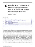
Fugitive volatile emissions refers to the minute amounts of process gases or fluids,
typically organic, that escape to the atmosphere by way of a number of different
mechanical routes. These include flange joints, sight glasses, packing and seals,
valve stems and control valves, tanks and storage vessels, hose connections, unions,
couplings, pumps, doors, and gaskets. A typical valve leak at the stem packing is
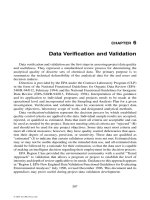
illustrated in Figure 6.1.
FIGURE 6.1
Valve stem leaks.
Fugitive VOCs
7099_C006.fm Page 141 Monday, July 17, 2006 11:59 AM
© 2007 by Taylor & Francis Group, LLC
142
Principles of Air Quality Management, Second Edition
Monitoring and replacement of leaking valves and flanges is a substantive part
of good management strategies and housekeeping. In some cases, tightening of the
packing nuts or bolts on flanges may be sufficient to reduce fugitive emissions. In
other cases, it may be required to replace older valves with hermetically sealed
equipment.
Proper maintenance should not be forgotten, as failure to keep filters, fans, and
air nozzles clean will upset the internal air patterns of a dryer or other equipment
and may result in “puffing” of contaminant-containing air from product entrance
slots, instead of achieving air in-flow.
Daily inspections for leaks save raw materials and reduce fugitive emissions.
Leaks can be in liquid or vapor form and can be continuous or periodic, depending
on where the leak occurs. Liquid leaks are detected visually and are relatively easy
to spot. Vapor leaks can be detected by a soap-and-water solution that is sprayed on
the locations where leaks may occur, or with more sophisticated equipment such as
portable volatile organic compound analyzers. Performing daily leak inspections can
prevent substantial fugitive emission losses from leaks that may go undetected for
several days.
Fluid pumps and packing around drive shafts in pumps may be sources of fugitive
organic emissions. Monitoring, repair, and replacement of such pumps with mag-
netically driven seal-less pumps are possible. This latter type of equipment (which
has been determined to be the best available control technology for refineries in
Southern California) operates by having the pump impeller inside of the pump
housing. The impeller is thus sealed from the environment and in line with the
moving fluid.
The driver transfers energy to the impeller shaft of the sealed unit by using a
magnetic field. This field, created by an outer magnetic ring, passes through a metal
containment shell at the rear of the pump and turns an internal rotor, which drives
the impeller, to produce the pumping action. The impeller shaft is supported by
bushings lubricated by the process fluid. The mechanical seals, which are prone to
leakage with externally mounted systems, are thereby eliminated. Such a piece of
hardware is typically designed for, and operates in, refineries and chemical plants
in which hydrocarbon-based liquids are being pumped.
Other techniques to reduce fugitive emissions from open tanks and, in particular,
plating solutions, include the use of additive chemicals. These surfactants reduce
misting by lowering the surface tension of tank solutions. The addition of tank covers
or floating surface media similar to ping-pong balls also has been found effective
in reducing surface evaporation and mists.
P
RODUCT
S
TORAGE
C
ONTROL
Breathing losses (vapor escape caused by air and gas temperature changes from
night to day) and working losses (vapor escape during filling) of volatile liquid
organic compounds from uncontrolled storage tanks are a source of fugitive emis-
sions. Control of emissions from product storage in tanks is performed by the use
of one or more of the following techniques:
7099_C006.fm Page 142 Monday, July 17, 2006 11:59 AM
© 2007 by Taylor & Francis Group, LLC
Stationary-Source Control Approaches
143
• Floating roofs
• Closed systems
• Secondary systems
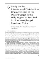
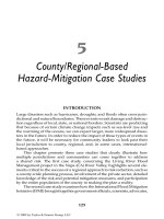
Floating roofs literally lie on the surface of stored liquids in a tank, thus preventing
vapor generation. The only losses are at the seals between the tank wall and the
floating roof edge. Figure 6.2 illustrates fugitive losses from the seals on a floating
roof tank. Emissions that escape from floating roofs and closed systems may be
further controlled with secondary systems that recover the volatile compounds. This
is accomplished by vapor recovery through condensers or absorbers.
An important aspect of control of organic fluids is proper storage to prevent
emergency or overfilling releases. Proper storage control can prevent accidental
releases. Monitoring is important to ensure proper product storage. Among the items
that should be considered for monitoring are:
• Fluid temperature
• Liquid level
• Liquid flow rate
• Pressure
•Tank stress
• Spill containment capacity
Gases are typically stored under pressure, so two critical items to monitor are
temperature and pressure. Liquids are normally stored at atmospheric pressure or a
slight positive pressure, so the critical items to monitor for them are temperature and
level. Liquid transfer, especially during loading and unloading, can be a point at which
spills occur either from accidental releases or through overfills. For these operations,
it is important to check the equipment, the fluid flow rate, and the tank levels.
Ongoing operator training and certification are additional management controls
appropriate to these operations.
FIGURE 6.2
Floating roof emissions.
Fugitive emissions
Seal envelope
Tank wall
Floating roof
Liquid
7099_C006.fm Page 143 Monday, July 17, 2006 11:59 AM
© 2007 by Taylor & Francis Group, LLC
144
Principles of Air Quality Management, Second Edition
M
ATERIALS
C
HANGES
Other management options include raw materials or compositional changes for the
processes in question. These include activities that minimize the use of these raw
materials, including greater efficiency of operation.
It is also possible to change the composition of raw materials such that air
emissions that are of a lower toxicity or volatility may be substituted in the process
while maintaining product quality. One recent example of such a materials change
was the substitution of a citrate cleaning solution for a chlorinated solvent, used to
decrease certain parts in the aerospace industry. The citrate compound, being a water-
based system, virtually eliminated halogenated organic solvent emissions from that
process line, which both saved money and eliminated hazardous air pollutant emissions.
Another example of substitution is in tank electroplating processes. Normally
aircraft parts are dipped in large vats of cleaning, rinsing, and plating solutions that
contain cadmium, to impart a special coating to the part. The use of aluminum ion
vapor deposition as a substitute for cadmium tank electroplating was the focus of a
large research project sponsored by the Air Force Civil Engineering Support Agency.
For those aircraft parts that do not have internal cavities or small clearances, it
is possible to suspend the parts on a rack in a vacuum tank, which then becomes
the ion vapor processing chamber. The racks become the electrode of a high-voltage
circuit that, when the chamber is evacuated, gives the parts a negative charge.
A small amount of argon gas is bled into the system, and high voltages are
applied to the parts. Thin strands of aluminum wire on the lower portion of the chamber
are vaporized, and as they pass through the glow discharge set up by the ionized
argon gases, the aluminum is ionized. These positively charged aluminum ions are
then attracted to and are neutralized on the negatively charged parts, thereby forming
a corrosion-resistant metal plating.
The ion vapor deposition process takes longer and costs more; however, the
hazards from cadmium emissions coming from the tank-plating operation have been
virtually eliminated. At the same time, contaminated waste waters from the electro-
plating systems are eliminated, and likewise, the hazardous sludge from electroplating
tanks is totally eliminated. In addition, there are no worker health and safety concerns
because the ion vapor deposition process is a totally enclosed system, and no haz-
ardous metals are used.
For large surface-coating operations, probably the most effective VOC reduction
technique is one in which the paints and topcoats are reformulated to eliminate
solvents entirely. In these processes, the resins, pigments, and other coating modifiers
are applied in a powder state, again by electrostatic processes, and heated. This
causes the resins to flow together, forming the smooth coat normally associated with
solvent-based processes. Following the heating operation, the coated parts, such as
automobile bodies, are run through radiant lamp arrays, which cause the semiliquid
material to cure into a hard and tough coating.
Switching from solvent-based to water-based paints and surface coatings is
another technique used to eliminate hydrocarbon emissions. Reformulation of the
coating materials is required to disperse the pigment particles and resins evenly
7099_C006.fm Page 144 Monday, July 17, 2006 11:59 AM
© 2007 by Taylor & Francis Group, LLC
Stationary-Source Control Approaches
145
throughout the coating. This requires some additives or detergents or small amounts
of alcohols or ketones to decrease the surface tension of the fine particle sizes in
the new coating. To some degree, these coatings are still experimental, but they are
gaining acceptance in a large number of surface-coating applications.
PROCESS-OPTIMIZING ACTIONS
The second approach is to optimize processes for air pollutant emission reductions.
A wide range of process changes that lead to lower air contaminant emissions is
possible. One of the early attempts to modify processes was to “de-rate” the unit.
De-rating occurs by operating a process or system at less than its maximum capacity,
which generally leads to a lower emission of air contaminants. This measure, how-
ever, leads to poor energy efficiency and lower production. It is not, therefore, high
on the list of potential management options.
Many processes and their emissions are sensitive to temperatures or speed of
operation or other control room settings. With portable analyzers, it is possible to
run a series of parametric tests of operational parameters versus air contaminant
emission rates and then select those operating conditions or ranges at which emis-
sions are at their minimum.
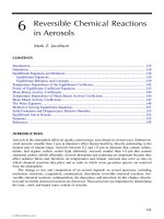
Modifications of line speed, as well as processing time, may have significant
impact on air contaminant emissions. In one situation, emissions of CO and HF
from a semiconductor plasma etch system used in the production of printed wiring
board substrates were found to be proportional to the amount of time that it was
operated. The process was normally run on a 30-minute mode that ensured that the
product met the quality standards of the printed boards. It was found that shortening
the time from 30 minutes to 22 minutes caused approximately a 40% reduction in
CO and HF emissions with no change in product quality. Figure 6.3 illustrates this
effect. The residual gases were then vented to control devices.
FIGURE 6.3
Carbon monoxide emissions versus time.
0
0
1
2
3
4
481216 20 24 28
Time, minutes
CO %
Amount
eliminated
Plasma etch process
Test 1
Test 2
Test 3
7099_C006.fm Page 145 Monday, July 17, 2006 11:59 AM
© 2007 by Taylor & Francis Group, LLC
146
Principles of Air Quality Management, Second Edition
Another example is seen in gravure presses, which coat inks onto continuously
fed fiberboard or other substrate material. Emissions of VOCs from the evaporation
of solvents in the inks occur as the web-fed press moves the substrate material from
one station to another before sending it to a dryer.
Operational improvements included reducing web speed, which will reduce the
amount of solvent vapor drag-out. High web speeds entrain air, which draws addi-
tional solvent vapor from the ink coating operation into the open spaces between
rollers. Lowering the static pressure within the web or roller enclosure also served
to increase the capture of fugitive VOC emissions.
Other common sources of evaporative solvent emissions from gravure presses
are insufficient temperature, ink that is too thick, slower-drying ink than that for
which the unit was designed, and underdesigned dryer systems. Each of these
problems may be addressed in a management or process optimization procedure that
may reduce solvent losses by as much as half of the total solvent used.
COMBUSTION MODIFICATIONS
Combustion modifications represent another area of contaminant reduction possi-
bilities. Combustion may be optimized (
emissions minimized
) by modifying how
the combustion takes place. For instance, it has been found that lowering the usual
amount of excess air in the exhaust gas of boilers yields lower oxides of nitrogen
concentrations.
Oxides of nitrogen are key contaminants that form photochemical ozone and
are largely emitted from combustion sources. A number of possible modifications
may be made to the combustion process to lower NO
x
without adding back-end
hardware or changing the fuel.
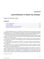
NO
x
formation is a function of the adiabatic flame temperature (Figure 6.4), as
well as the stoichiometric air/fuel ratio. So we find that most NO
x
strategies attempt
to reduce the maximum flame temperature and residence time of the combustion
gases at those high temperatures. This “thermal NO
x
” accounts for the majority of
the NO
x
formed in combustion systems and is greater than the NO
x
from fuel
nitrogen.
The first approach to lowering NO
x
emissions in large, multiburner boilers is to
use what is called a burners out of service (BOOS) combination. Figure 6.5 illustrates
such a combination, which reduced the NO
x
as noted. In this approach, a series of
burners is taken out of service and the balance of the fuel flow is provided to the
in-service burners.
Increasing the fuel flow through the burners that are in service decreases the
local air-to-fuel ratio. The rest of the required combustion air is provided by leaving
open the burner ports that are out of service. Thus, the overall NO
x
is reduced.
Burner modifications are possible. Emissions are lowered by changing the flame
geometries and turbulence. Research is ongoing to modify burners to allow for
localized gas recirculation and delayed mixing between fuel and air. This lowers the
local air-to-fuel ratio and the flame temperature, which reduces NO
x
formation.
Burners and air registers may all be modified to produce lower NO
x
without changing
the boiler or the fuel.
7099_C006.fm Page 146 Monday, July 17, 2006 11:59 AM
© 2007 by Taylor & Francis Group, LLC
Stationary-Source Control Approaches
147
Tight control of the oxygen available to combustion systems is possible with
single- or multiple-burner external combustion systems. These “oxygen trim” or
“low excess air” systems generally require continuous monitoring for exhaust gas
oxygen, CO or combustibles, and oxides of nitrogen. If the monitor readout is in
the control room, the operator is able to ensure that a stable and safe combustion
process is always present. These systems allow for operation of the system very
close to the stoichiometric air-to-fuel ratio; however, close attention must be paid
to the level of oxygen in the overall system as well as to CO and combustible gas
levels.
It is possible to reduce the oxygen to too low a level, at which point the flame
may become unstable. If this happens, it may begin pulsating at a natural harmonic
frequency in the 10–20-Hertz range. At that point, the boiler itself may begin
resonating in phase that, if unattended, will destroy the structural integrity of the unit.
For multiple burner boilers, it is also possible to provide a staged combustion in
the furnace. In this approach, different horizontal rows of burners are operated in either
a fuel-rich or fuel-lean mode. In the fuel-rich zone, near the burner, NO
x
concen-
trations are reduced. When the flames move up to the higher regions of the boiler,
where more air is available, the overall combustion becomes air-rich or fuel-lean.
FIGURE 6.4
NO
x
concentrations versus temperature and residence time.
Recirculation zone
NO formation
3000°F for 2.0 sec 50 ppm
Peak
adiabatic
temperature
Primary zone - adiabatic NO formation
3800
°F for 0.05 sec 1500 ppm
2800 3000 3200 3400 3600 3800 4000
Te mp er ature,
°F
6
000
1000
100
10
Nitric oxide
(
NO), ppm.
NO formed in 1.0 se
c
0.1 sec
0.01 s
ec
7099_C006.fm Page 147 Monday, July 17, 2006 11:59 AM
© 2007 by Taylor & Francis Group, LLC
148
Principles of Air Quality Management, Second Edition
In the higher regions of the boiler, there are open air injection ports called NO
x
ports, which provide that final amount of air to complete the combustion and to
lower overall CO and combustible gas concentrations in the flue gases. Oxides of
nitrogen are reduced while the overall combustion process maintains its required heat
output. Figure 6.6 is a schematic illustration of a power boiler with staged combus-
tion zones.
Reburning, often used in combination fuels, produces a very similar pattern to
that seen in the previous figure. Reburning involves passing lower-burner fuel-rich
combustion gas products up to a secondary flame. This process is designed to reduce
NO
x
without generating CO. It diverts a fraction of the total required fuel from the
primary combustion zone burners to the upper burners, to create a secondary fuel-
rich flame zone. Sufficient air is then supplied higher in the boiler to complete the
FIGURE 6.5
NO
x
reductions for gas and oil boiler with burners out of service,
( )
Gas, normal comb., All Burners in Service
Furnace excess O
2
Gas, staged comb., 3rd Row BOOS
Oil, staged comb., 4 BOOS
Oil, normal comb., All Burners in Service
Gas Oil
4
3
2
1
Burner patterns
(2.4)
(2.0)
(2.7)
(3.0)
(3.2)
(3.7)
(2.8)
(3.1)
150
0
200
250
300
350
400
4
5
0
130 140 150 160 170 180
Load – MW
NO – ppm
(
corrected to 3% O
2
, dry)
7099_C006.fm Page 148 Monday, July 17, 2006 11:59 AM
© 2007 by Taylor & Francis Group, LLC
Stationary-Source Control Approaches
149
oxidation process. Lab tests indicate that a maximum reduction in NO
x
is achieved
when the lower reburning zone stoichiometry is set at approximately 90% of theo-
retical air.
Flue gas recirculation is another technique used to reduce NO
x
by reducing flame
temperatures. This requires a hardware modification and additional power, as up to
FIGURE 6.6
Power boiler with staged combustion and dual fuel.
Secondary superheater
Platen
superheater
Primary
superheater
Reheater
Economizer
Control
dampers
Air heater
Forced-draft
fan
Burners
140 ft
Gas
Air
Air
Coal
7099_C006.fm Page 149 Monday, July 17, 2006 11:59 AM
© 2007 by Taylor & Francis Group, LLC
150
Principles of Air Quality Management, Second Edition
20% of the exhaust gas is recirculated back into the combustion air supplied to the
burner system. In this approach, increasing amounts of flue gas are recirculated into
the combustor, which lowers the amount of available oxygen. This step acts to lower
the overall combustion-produced thermal NO
x
. Initially, a very large reduction for
a very small amount of recirculated gas may be found (i.e., 50% NO
x
reduction for
a 5% gas recirculation).
With flue gas recirculation, there are also concerns about space utilization, as
well as capital and energy costs. This approach finds its greatest use in smaller
package boilers, typically those operated with only one burner firing on natural gas.
It is possible to purchase low-emission burners that give equivalent combustion
temperatures and lower pollutant emissions. These burners, coupled with stack
oxygen and CO monitors, allow significant optimization of combustion gas emissions.
FIGURE 6.7
Combustion turbine NO
x
versus water injection–liquid fuels.
Jet A, A engine 325 hours
Methanol, B engine 500 hours
Indicates 140.1 b/hr
limit for load (MW)
indicates
Base load
~ 25 MW
18.5
MW
12.5
MW
1982 EPA NOx
Limit, 75 ppm
New gas turbines
23
MW
25 MW
17 MW
6 MW
Jet
A
240
220
200
180
160
140
120
100
80
60
40
20
0
0 0.2 0.4 0.6
Methanol
Water injection rate, LB water/LB fuel
NOx, ppm at 15% O
2
7099_C006.fm Page 150 Monday, July 17, 2006 11:59 AM
© 2007 by Taylor & Francis Group, LLC
Stationary-Source Control Approaches
151
Fuel modifications are another method of reducing air contaminant emissions.
Fuels, being easier to change than hardware, are therefore an option for source-
reduction approaches.
Another option is to introduce water or steam into certain combustion processes
that will act to lower the flame temperature. This option finds its best utilization in
combustion turbine emission reduction programs. Significant NO
x
reductions may
be achieved by injecting liquid water or steam into the combustor can during
operation. Figure 6.7 illustrates the NO
x
reductions made possible by injecting water
into a 25-MW gas turbine driving a power generator. In this figure, we see the effects
on NO
x
for both Jet A and methanol fuels. Methanol without water injection presents
a significant reduction by virtue of its own combustion characteristics and lower
adiabatic flame temperature.
FUELS AND FUEL MODIFICATION
E
FFICIENCY
With respect to fuels, we may either minimize their use, modify them, or choose
other alternatives. Processes that increase overall efficiency or that can take advan-
tage of lower steam production yield lower fuel use and, therefore, lower air pollutant
emissions.
S
ECONDARY
U
TILIZATION
Any operational or hardware change that minimizes or reduces the amount of fuel
consumed overall in a combustion system will emit lower air pollutant mass emis-
sions as a result of lesser amounts of fuel being burned. As a consequence, a great
deal of attention has been focused on waste heat boilers, steam generators, and
drying operations.
In these approaches, a high-temperature utilization of heat, such as in a boiler,
incinerator, or other fired process, exhausts waste heat in the form of hot gases.
These gases may be channeled into another process that is able to use the lower
temperature gas in a secondary process. Typical of such an operation would be a
system in which combustion gases, after being used to make steam, are used to
generate hot water or some other secondary use. The secondary use could be for
building heat, to drive another process, or in the case of natural gas-fired systems,
to perform a drying operation, as in the production of paper goods. This is termed
cogeneration
.
Some newer approaches use the heat of condensation of the water vapor in stack
gases. This energy may be used for space heat or to provide a working fluid for
another process such as a boiler or air conditioner. In these approaches, the stack
gases that contain large quantities of water vapor are ducted through heat exchangers,
which extract the heat and lower the gas temperature to the water dew point. At that
point, the latent heat of vaporization is given up in the heat exchanger, and the water
condenses out to the liquid state. This procedure provides large amounts of energy
for use in other processes without requiring any further use of fuels or generation
of air pollution.
7099_C006.fm Page 151 Monday, July 17, 2006 11:59 AM
© 2007 by Taylor & Francis Group, LLC
152
Principles of Air Quality Management, Second Edition
Problems with this approach may occur as a result of the possibility of corrosive
gases being present in the exhaust and the lack of buoyancy of the final stack gases.
Contaminants, such as NO
2
or SO
2
, form nitric or sulfuric acid in the water con-
densing in the heat exchangers, causing both corrosion and wastewater disposal
problems. Lower exhaust gas plume buoyancy could cause high noncondensible air
pollutant concentrations downwind from a cooled exhaust as a result of lessened
dispersion.
F
UEL
S
WITCHING
The simplest approach to lowering emissions from fuels is to change the fuel itself.
In general, coal is a “dirtier” (greater air pollutant emissions per unit of energy) but
cheaper fuel than oil. Oil is a dirtier but cheaper fuel than natural gas. Therefore,
where possible, switching from a solid or liquid fuel to natural gas could be a
preferable alternative to building or adding an air pollution control system.
However, there are other concerns involved with fuel switching, as combustors
are designed for one type of fuel, with a backup fuel as a temporary replacement.
The distinction is in the size, temperature, and luminosity of the flame itself for a
given fuel. In a large power boiler, changes in flame geometry resulting from a fuel
change may have a significant effect on temperature distributions in the hot water
and steam passages in the boiler.
F
UEL
B
LENDING
It is also possible to blend fuels for lower overall emissions. One such blend would
be made using a pulverized coal boiler in conjunction with natural gas burners. This
mix would lower the emissions of particulate matter and sulfur oxides and allow
use of the cheaper fuel. A similar system was shown earlier in Figure 6.6.
Apart from gas and coal combustion systems, the general approach is to blend
high-sulfur and low-sulfur coals to meet emission limitations. Such a blending
operation, particularly with a solid fuel such as coal to meet one emission limitation
(SO
2
), requires very tight control on the blending processes in conjunction with
monitoring data from continuous emissions monitors.
In one such case in Detroit, a power plant was able to blend three coal types —
low-sulfur western and southern coals and midsulfur eastern coals — in varying
percentages. The purpose was to balance sulfur content and cost and to meet the
statutory SO
2
emission limit. In general, the low-sulfur western coals, which
accounted for almost 50% of the blend, were required to meet the emission limita-
tions. There are minor capital expenditures for such blended systems, as western
coals are more prone to spontaneous combustion than the eastern coals. Likewise,
additional costs for reducing boiler fouling and slagging are usually incurred.
Depending on the location, a switch from a high-sulfur coal to a low-sulfur coal
is possible, again depending on the SO
2
limits. However, a complete switch from
one to the other can have far-reaching implications for both operation and emissions.
Coal varies considerably in moisture, ash, sulfur, and heating values. As seen in
Chapter 3, many low-sulfur coals have a lower heating value than the higher-sulfur
7099_C006.fm Page 152 Monday, July 17, 2006 11:59 AM
© 2007 by Taylor & Francis Group, LLC
Stationary-Source Control Approaches
153
coals; therefore, more fuel is needed to produce the same amount of energy. As a
result, the amount of ash and moisture that will pass through the system to maintain
power output requires additional efforts to maintain boiler efficiency. Disposal of
greater quantities of waste products, such as fly ash and bottom ash, requires addi-
tional space and cost for the disposal of those residuals.
F
UEL
C
LEANING
Coals are particularly amenable to cleaning because the major contaminants are
commingled minerals and soils. Favored techniques to beneficiate coal are grinding
the coal and washing it with water to remove the coal particles (which tend to float)
from the rock and soil fractions. These latter fractions are much denser than coal
and fall to the bottom of the water wash.
Other possibilities include froth flotation, in which air is also injected into the
water-washing step. In this process, small bubbles adhere to the coal particles, which
help the particles rise to the top of the water. At that point, the coal is discharged
from the top of the fluid, dried, and used as fuel. The solid soils — minerals and
rocky material — are separated and reinterred. The water is reused after cleaning.
Figure 6.8 illustrates one type of coal cleaning unit.
It is possible to grind coal into a powder and separate it by an air classification
process. In this process, pulverized coal is discharged over an air curtain. The coal
particles, being less dense, float on the air cushion or jet until they are collected and
sent to bunkers for storage. The more dense materials tend to fall out of the air
cushion and are removed as solids. In modifications to this process, large
cyclones
(
q.v.
) are used to separate out pyrites, which are much more dense than the coal
FIGURE 6.8
Froth flotation cell.
Air
Mechanical
agitator
Clean coal froth
Clean coal froth
Fine bubbles
7099_C006.fm Page 153 Monday, July 17, 2006 11:59 AM
© 2007 by Taylor & Francis Group, LLC
154
Principles of Air Quality Management, Second Edition
particles. Pyrites are iron sulfide minerals, so their removal reduces the sulfur oxide
and ash/particulate emissions. This approach avoids the problems of dealing with
waste water and coal drying before utilization. It is not as effective in removing other
noncombustible materials, however, and it is also subject to fugitive particulate
losses.
It is possible to clean fuel oils of water-soluble contaminants. In one project in
California, certain fuel oils contained significant amounts of salt. This pollution
contributed to boiler fouling, slagging, increased corrosion, and increased emissions
of sulfuric acid droplets, rusty particulate matter, and acid fallout in nearby com-
munities. In one field demonstration, it was shown that by injecting fresh water into
the fuel oil during transfer, the dissolved salts were transferred to the water solution.
Following a period of roughly 2 days, the water droplets containing the salt coalesced
by gravity separation into the bottom of the storage tank. This reduced the oil’s total
salt content from over 100 ppm to less than 15 pm. This greatly beneficiated the
fuel oil and cut the slagging, fouling, and air contaminant emissions dramatically.
The contaminated water was removed by a simple decanting operation, which then
went to a water treatment operation.
Natural gases may be beneficiated by control of sulfur content. From an air
pollution perspective, little else is necessary to beneficiate gas because of the small
amounts of contaminants naturally occurring in gas.
A
DDITIVES
Fuel oil additives are sometimes used in an attempt to lower air emissions and to
control fouling of boiler surfaces. They influence the size of fuel droplets in oil
burner combustion systems by changing the viscosity and surface tension. Changing
the droplet size in the burner will change the evaporation rate, which will change
the heat flux. Combustion parameters and particulate emissions are influenced by
these changes. Some reductions in visible plume opacity have been noted in past
trials with additives.
Fouling increases emissions indirectly by lowering thermal efficiency (which
requires greater fuel). Fuel oil additives influence fouling by modifying the chemical
composition of tube deposits inside the boiler. The primary effect is to produce a
high–melting point ash deposit that is powdery or friable and that is easily removed
by a soot blower or a lance for control by back-end control systems. When the ash
is dry, corrosion is reduced, and large particulate emissions may be reduced. In some
cases, alkaline materials are added in attempts to reduce acid gas emissions.
F
UEL
M
ODIFICATIONS
Natural gas, oil, and coal form the backbone of fossil fuels for the foreseeable future.
However, modifications of some of these fuels, and in particular those involving
coal, will find their place as “niche” markets.
Mixtures of crushed coal and oil in slurries are one attempt to use a resource
that is in plentiful supply. The benefit of a coal–oil slurry is that a relatively cheap
fuel may be used that has the advantages of oil. The primary advantage of liquid
7099_C006.fm Page 154 Monday, July 17, 2006 11:59 AM
© 2007 by Taylor & Francis Group, LLC
Stationary-Source Control Approaches
155
fuels is that they are easily pumped, and thus combustion parameters and fuel mixing
are more easily controlled. In addition, particulate emissions and sulfur oxides are
lower than with pure coal combustion.
Other very specific blends of fuels include adding oxygenated compounds, such
as alcohols, to gasoline to improve the emissions characteristics of the fuel. The
effect of adding oxygenated components to liquid fuels has the effect of “leaning
out” the air-to-fuel ratio, which results in reduced hydrocarbon and CO emissions.
The addition of oxygenated fuel components serves to reduce flame temperatures
(and NO
x
) and to reduce the emission of heavier–molecular weight compounds that
are more difficult to oxidize. The net effect of such reformulated gasolines is to
increase the combustion efficiency and lower air emissions.
Another modification is to take a primary fuel, such as coal, and convert it to a
synthesis gas. In this approach, a fuel that is basically carbon, like coal, is reacted
at high temperatures in the presence of steam to yield a mixture of carbon monoxide
and hydrogen gas [Equation (6.1)]:
Carbon (C) + H
2
O
→
CO + H
2
. (6.1)
This synthesis gas may then be used as any other gaseous fuel without the problems
of ashes, particulate matter, or pyritic sulfur entering into the combustion reactions.
This water–gas reaction is beneficial; however, it requires the input of heat and high
pressure and leaves behind a solid residue.
Direct pyrolysis of solid fuels is another approach in which a synthesis gas may
be generated from a lower-grade fuel. In this process, the solid fuels (of whatever
type) are heated to drive off moisture and then are raised to higher temperatures to
drive off the volatile organic materials. These gases may then be used directly in a
combustion process or piped elsewhere for use. In general, these approaches for
pyrolysis fuels are limited by the distance between the pyrolyzation process and the
location of the usage of the gas.
Depending on the availability of other components, such as hydrogen or natural
gas, the fixed carbon may be further oxidized to a CO containing gaseous fuel, which
likewise may be used as a synthesis gas. These pyrolysis-derived gaseous fuels are
generally used in a facility in which the raw materials are readily available and a
large quantity of synthesis gas may be used in close proximity. These on-site uses
are to provide steam to a process or provide hot exhaust gases to dry out other
materials or provide heat for other plant reactions.
The alternatives are the
biogenic fuels
, which are generated by the operation of
natural processes (i.e., fermentation) on biomass, such as wood chips, walnut shells,
and so on.
Methyl alcohol and ethyl alcohol are two alternative fuels that may be generated
from the biological degradation of wood, grain, and biomass to yield an alcoholic
short-chain hydrocarbon. After separation, these alcohol fuels may be used directly
or as an additive to a composite-fuel mixture. The problems associated with these
fuels are the amount of heat and processing required to convert biomass materials
into a clean, dried alcohol. Of course, residual materials must also be disposed of
as solid waste.
7099_C006.fm Page 155 Monday, July 17, 2006 11:59 AM
© 2007 by Taylor & Francis Group, LLC
156
Principles of Air Quality Management, Second Edition
Biomass materials may also be used directly as solid fuels. Wood chips and
walnut shells have been used in place of other fuels in pulverized combustion systems
and in hogged fuel or waste fuel boilers. Where a supply of these materials is plentiful
and the transportation distance is short, such fuels may find a niche in providing
process heat or steam. However, these materials tend to be lower in heating value
than the primary fossil fuels and to generate particulate emissions. The latter erode
gas passages, ductwork, combustors, and process equipment.
Other biomass fuels, such as landfill gas, may be used either directly on-site to
provide energy to a combustion turbine or a reciprocating engine to directly drive
a power generator. They may be beneficiated by the removal of moisture, carbon
dioxide, and other heavier–molecular weight constituents and then sold as an
upgraded “natural” gas or fired in a conventional boiler as a natural gas substitute.
Again, the cost implications are that, because of the lower heat content of landfill
gas, it is generally more cost-effective to burn the gas directly and to provide either
steam or power on site.
Biodiesel oils, from plant sources, may beneficiate other liquid fuels, but they
are not a substitute for the original fuel oil.
F
UEL
R
EFINING
For liquid fuels, it is possible, through additional refining or reforming of the basic
fuel hydrocarbons, to lower the sulfur content and residual minerals to provide a
beneficiated fuel. This provides a cleaner fuel for the end user but leaves the residual
materials of sulfur, ash, and so on at the refinery for disposal.
Reformulation of fuels and specification changes to lower the amount of
heavy–molecular weight compounds may result in cleaner combustion, fewer depos-
its, better efficiency, and lower emissions. One such measurement is the T
90
tem-
perature of the fuel. This is represented by the upper-right-hand portions of the
distillation curves seen earlier in Figure 4.5.
A recent study found that specifying a lower T
90
(the boiling point of the 90th
percentile of the fuel) resulted in lower emissions of nonmethane hydrocarbons,
benzene, formaldehyde, acetaldehyde and 1-3, butadiene with no changes in CO
emissions and only a small increase in NO
x
emissions.
PLANNING AND DESIGN
Primarily for new sources, air quality management options have their biggest effect
at the design stage rather than as a back-end control system or a source modification.
In general, these approaches involve the entire stationary source from location to
layout to types of technologies in use.
G
EOGRAPHIC
L
OCATION
The first effort is to choose a location, where possible, that optimizes ventilation
and natural dispersion. A location that is more open to horizonal wind movements and
unlimited vertical mixing would be preferable to one in which a low inversion is
7099_C006.fm Page 156 Monday, July 17, 2006 11:59 AM
© 2007 by Taylor & Francis Group, LLC
Stationary-Source Control Approaches
157
present. In this scenario, the emitted gases are more easily diluted by natural pro-
cesses. This is assuming that process changes, material substitutes, and so on have
already been implemented in the planning stages to reduce potential emissions before
the facility has been designed.
Where possible, the location may be chosen as a function of zoning. Placement
of a facility in an industrial location, or with a sizable buffer distance between
industrial or commercial districts and residential areas works to abate nuisance com-
plaints resulting from odors and particulate fallout. In addition, “hot spots” (localized
areas with high concentrations caused by point sources) may be minimized.
In planning a layout of a facility, the minimization of fuel, raw materials, or end
product movement will inherently lower potential air contaminant emissions. Min-
imizing fuel movement, by tanker, truck, or pipeline, will lower fugitive losses, as
well as catastrophic spills or leaks.
Minimizing handling and movement of raw materials and providing storage
enclosures (rather than open storage) and enclosing conveyor belts, storage bins,
and so on will work to lower the amount of fugitive emissions. Minimizing move-
ment of products will generally lower overall fuel requirements for forklifts or for
electrical power consumption in moving materials or products from one location to
another and to the final loading dock.
LOWER-EMISSION SYSTEMS
In a newly designed facility, it is possible to take advantage of new technologies
that give greater overall efficiency of energy use, thereby lowering costs and fuel
combustion emissions.
Where processes require both heat and either steam or electrical power, consid-
eration could be given to cogeneration systems. These systems burn fuel to drive a
turbine generator, which provides electrical power; the hot gases that exhaust from
the combustion turbine are used in processes that require heat for drying or curing
materials or products. A cogeneration system in Southern California was built that
used natural gas as the clean fuel to drive a 25-MW electrical power generator; it
then used the hot gas to dry the paper diapers, which was the main product of the
facility.
Other combustion technologies, such as fluidized beds, may be used where
gaseous or even solid fuels may be burned to provide controlled temperatures. In a
fluidized bed combustor, the fuels are dispersed in a swirling mass of solid material,
such as sand, and ignited. The temperature of the hot gases is carefully controlled
to provide a uniform temperature. This temperature is relatively low, but the sand
or other media has high turbulence, which contributes to complete combustion with
uniform heat transfer. Fluidized bed systems can be used to carefully control emis-
sions in an NO
x
-sensitive area while providing high-quality steam for other pro-
cesses. Dirtier fuels, such as coal, may also be used in such a system, as it is possible
to add alkaline materials, such as limestone, which will react with acid gases during
combustion.
Where possible, new energy technologies may be used to provide local power
or heat. These technologies include fuel cells and solar systems to provide energy
7099_C006.fm Page 157 Monday, July 17, 2006 11:59 AM
© 2007 by Taylor & Francis Group, LLC
158 Principles of Air Quality Management, Second Edition
for specific processes. These options are, of course, limited by the relatively low
energy density of such systems and find only a limited use in specific niches.
In some cases, control equipment may be integrated into the process system to
provide useful heat or energy. A case in point is where a regenerative thermal oxidizer
was installed on a VOC emitting process; the heat generated in the oxidizer was
extracted in a heat exchanger and used to preheat the gases coming into the control
device. This lowered the energy requirements for the control system and lowered
the air emissions associated with providing that energy.
GREATER EFFICIENCY
In designing processes or buildings, “energy-efficient” facilities are a contributing
factor to lower emissions, as less energy has to be used to provide space heating or
cooling for the occupants.
The most effective technique, for either new or existing sources, is to provide
the same amount of work in a process at a lower horsepower. Because 63% of the
energy used in the U.S. industry is consumed by electric motor–driven equipment,
increasing the efficiency of motors will reduce the horsepower used. This will lower
the amount of fuel burned (and air emissions) to provide the electrical energy
required. This reduction can be accomplished by installing newer, high-efficiency
motors, sizing motors to the specific job, and using adjustable-speed drive systems.
REPOWERING
Repowering is another approach in which an older technology, such as a steam
boiler, is replaced by a newer one, such as a combustion turbine or a combined cycle
system. If a use for waste heat, hot gases, or steam is nearby, a cogeneration system
could be built, satisfying both needs.
EMISSIONS CHARACTERIZATION
After all source-reduction, management, and planning activities have been carried
out, it is necessary to fully characterize air pollutant emissions from a given process
before the design or installation of back-end controls. Air pollution control systems
or back-end techniques will always be required, because there will always be some
emissions, because no process is 100% efficient in the conversion of raw materials
or fuels to end products.
The first step in control system selection is to characterize the gas stream that
will be carrying the contaminants from the source to the control system. Velocity,
total gas flow rate, water content, temperature, and pressure of the exhaust gases are
critical. Each of these components may significantly influence the control device,
as well as the materials used to contain the flow and collect the air contaminants.
It is not sufficient to know just the average values. It is important that one also
understand the maximum possible range, both on the high and the low side, for each
parameter, as any control system must handle excursions, process upsets, or low
operating conditions.
7099_C006.fm Page 158 Monday, July 17, 2006 11:59 AM
© 2007 by Taylor & Francis Group, LLC
Stationary-Source Control Approaches 159
Likewise, an understanding of the emitting process itself is needed. This includes
the mass throughput, temperature, reaction rates, and ratios over the course of the
process. Likewise, one must fully understand whether the process is a steady-state
one (coating a material on a web or substrate) or whether the process is a cyclic one
(i.e., batch chemical manufacture) with surges in temperature, mass and volume
throughput, or emission rates. Control room parameters that determine process rates
must also be monitored, as they are generally indicative, directly or indirectly, of
air contaminant emissions.
Emission changes are illustrated by the production of steel in a basic oxygen
furnace. Here pure oxygen is injected, by a water-cooled probe, into molten pig iron
in the basic oxygen furnace. The oxygen rate is modulated to provide a burn-off of
excess carbon in the bath until the appropriate level of carbon (and steel composition)
is reached. This process produces highly variable emissions of particulate matter and
CO and illustrates that any control system must provide for such surges or variations.
For each contaminant, one must understand its physical state (gas, solid, or
liquid) and its concentration. Both extreme values and average concentrations are
important. Likewise, the mass emission rate of such contaminants must be fully
characterized, lest the control system be oversized, thus increasing capital costs, or
undersized, with the potential for noncompliant emissions of air contaminants.
The chemical and physical properties of each contaminant must also be fully
characterized. Chemical properties of the contaminants include knowledge of
whether the material is organic or inorganic and its reactivity to other gases in the
gas stream, to moisture, or to oxygen. These reactions may significantly affect the
choice of a control system. Likewise, the oxidation potential of the contaminant, as
well as its pH and corrosivity in either the gaseous or liquid state, must be known.
When exhaust gases pass over a cold spot that induces moisture condensation,
corrosive acid contaminants may dissolve in the liquid and concentrate in those areas
of the control system. Such a point might be an uninsulated area in the duct work,
an expansion joint, a heat exchanger, and so forth.
The physical properties of the contaminants are of concern as well. The water
solubility of each contaminant in the gas stream will affect the choice of control
system, as well as the potential discharges of wastewater generated in the system
(either intentionally or unintentionally). If the contaminant is a particle, the size,
density, and abrasiveness of the particulate must be known. Knowledge of whether
the particulate may be “sticky” can affect the choice of control system and the
ductwork design. The ducting containerizes and conveys the exhaust gases and
particulate matter from the process source to the control device.
COLLECTION OF AIR CONTAMINANTS
If a collection system is not provided as an integral part of the source equipment,
such as duct work and chimney for a boiler, provisions must be made for collecting
the contaminants. These include direct emissions (i.e., those escaping from a met-
allurgical operation) as well as fugitive emissions from transfer points or open
surface operations.
7099_C006.fm Page 159 Monday, July 17, 2006 11:59 AM
© 2007 by Taylor & Francis Group, LLC
160 Principles of Air Quality Management, Second Edition
Knowledge of whether the contaminant is a vapor or a solid particulate is
required in designing or evaluating a contaminant-capture system. Both types of
contaminant emissions are momentum controlled; however, particles are less influ-
enced by gas movement than vapors.
Provisions for capturing the emission by a hood or a shroud during normal
operations, movement of raw materials and final products, and maintenance are
important. The temperature and buoyancy of the gases escaping from a surface, such
as an open-top degreaser or a molten metal bath, must be known, as they significantly
affect the direction of movement of the contaminants into the surrounding air.
Figure 6.9 illustrates a typical hooding arrangement intended to collect emissions
from an open-top process, such as a metallurgical operation.
Once the contaminant gases are containerized, they must be conveyed by a local
exhaust system to the control device. Particulates are of the greatest concern because
their density and inertia influence whether they will “fall out” (by sedimentation)
in the exhaust ducting before the control device. The conveying velocity needed to
suspend particles is a direct function of the particle shape and density and may vary
from as low as 2,000 feet per minute to as high as 5,000 feet per minute. The shape
of the ducting is another important consideration to avoid recirculation zones or
dead zones that will cause particles to drop out and clog the system.
One of the key parameters to optimize in an air pollution control system is the
total amount of air that the air pollution control system must handle. In a fugitive
control system, such as an open hood, a large amount of air must be drawn into the
system to capture the particulates and gases that may be emitted. However, the intake
velocity to capture particulates decreases exponentially with distance from the duct-
work entrance. Therefore, very large quantities of air must be drawn in to provide
sufficient velocity at points farthest from the hood to guarantee contaminant capture.
These concerns have led to innovative ways in which to use other air properties
to lower the amount of total air drawn into the system. Such a system would be one
in which a “slot hood” is placed along the sides of a liquid-containing tank. The
FIGURE 6.9 Canopy hood over a process tank.
Process
7099_C006.fm Page 160 Monday, July 17, 2006 11:59 AM
© 2007 by Taylor & Francis Group, LLC
Stationary-Source Control Approaches 161
tank may contain a water bath, acid bath, molten metal, or solvent. Slot hood designs
take advantage of air entrainment over an open surface. The higher the velocity, the
greater the entrainment. Thus, a long slot with a very thin opening just above the
surface of a molten or liquid bath would entrain more capturing air at the far side
of the tank than an equivalent volume contaminant capture system with an overhead
or suspended hood. Figure 6.10 illustrates such a slot hood design for control of
fugitive emissions from a liquid bath.
Additional refinements to the slot hood approach have been to provide a “push-
pull” system that takes advantage of additional entrainment of air in a high-velocity
jet. On one side small, compressed air jets sweep across the surface of the liquid
bath, aimed right at the suction of the slot hood. This set-up provides for even greater
contaminant collection at a fairly low flow rate. A push-pull system requires a source
of compressed air, but this is considered a nominal cost because of the lower expense
of smaller fans and control systems.
Other concerns for exhaust systems and control devices are for the materials of
construction. Key concerns are for abrasion or erosion of the gas passage materials
when particulates are present, as well as for fracture or breakage of control or exhaust
system components under thermal stress. This occurs when there are rapid temper-
ature swings in the process. Leaks may result.
Corrosion may also be induced by the formation or use of liquid water in the
process. The combined effects of moisture, temperature, and air (quite apart from
corrosive gases) may cause weak points or areas under thermal stress or thin wall
areas to rust. These areas may suffer abrasion or be corroded through, causing losses
of collection efficiency and increased emissions.
Of concern from an economic standpoint is the sizing of the equipment to allow
for proper gas flows and controls at an optimum cost. In general, the horsepower of
the exhaust fan is one of the largest single determinants of cost. An understanding
of fan laws, as they relate to energy consumption, are important to factor into exhaust
control system designs. The fan laws are:
FIGURE 6.10 Slot hood for control of emissions from open-surface tanks.
Exhaust ductLiquid level
Plenum
7099_C006.fm Page 161 Monday, July 17, 2006 11:59 AM
© 2007 by Taylor & Francis Group, LLC
162 Principles of Air Quality Management, Second Edition
•Fan volume varies directly with speed
•Fan pressure varies with the square of volume
•Fan power varies with the cube of the volume
The total volume for venting any given process is a direct function of the speed of
the fan. If we double the fan speed, we double the volume of gas being drawn
through the control system.
The total pressure of the system increases as a square function of the volumetric
flow rate. Thus, if the volume is doubled, the total pressure required to be exerted
by that fan is four times the original amount. Thus, a significant pressure increase
requirement results from doubling the volume of gas being exhausted.
Of particular concern, as electricity costs are based on the amount of power
used, is the third fan law. This law states that if we double the volume of gas in the
same system, the power requirement will be eight times higher, as the power
increases with the cube of the volume being drawn through the system. Therefore,
the costs associated with a control system are significantly influenced by the required
power. This requires that the volumetric flow rate be carefully selected.
Even an increase in volume of 25% would lead to nearly a doubling of the power
requirements and the costs associated with it.
AIR POLLUTION CONTROL APPROACHES
For convenience, back-end control systems are divided into those designed for
gaseous emissions and those designed for particulate matter. It should be remem-
bered that few sources emit only one contaminant; therefore, most air pollution
control systems must take into account the entire range of contaminants, tempera-
tures, concentrations, and energy costs. Likewise, control systems designed for one
pollutant may often have some effectiveness for others.
Multiple control devices in series may be used for contaminant control. In these
systems a lower-efficiency simpler device is usually placed first in line to collect the
bulk of the contaminant emissions, and the second device functions as a “polishing” unit.
GAS CONTROL TECHNOLOGIES
With gases, control systems are divided into two categories: process gases and
combustion gases. The process gases include volatilized organic compounds such
as solvents (i.e., perchloroethylene), fuel vapors (i.e., propane, hexane), and organic
chemicals (i.e., toluene, methanol, etc.) and acid gases. The acid gases include
hydrochloric acid, nitric acid, sulfuric acid, phosphoric acid, SO
2
, and NO
2
. The
combustion gases are carbon monoxide, products of incomplete combustion (fuel
fragments), sulfur oxides, and NO
x
.
For each of these gases, only a few types of control equipment are generally
available. The type of equipment used usually is matched to the physical or chemical
process that occurs in the equipment. Which piece of equipment, or combination of
devices, may be chosen depends on the gas stream and pollutant characteristics noted
earlier. It is therefore more appropriate to survey the equipment types and their
general attributes.
7099_C006.fm Page 162 Monday, July 17, 2006 11:59 AM
© 2007 by Taylor & Francis Group, LLC
Stationary-Source Control Approaches 163
For VOCs, for instance, the concentration of the organic compound strongly
influences the selection of a control device. In situations in which the concentration
falls in the percentage-by-volume range (i.e., 30%–40%), as in the displaced vapors
from filling an underground gasoline storage tank, a condensing process using a
chiller is the most useful system to use because it recovers the vapors for reuse.
Where the VOC concentration is in the low parts per million range (i.e., from
solvent evaporation), an adsorption system such as activated carbon is useful because
the adsorber acts at the molecular level to collect the molecules of solvent with high
efficiency. Also, with that system the solvent may again be recycled. Of course,
other VOCs, regardless of concentration, must be incinerated because of either
regulatory requirements or their high toxicity potential. Figure 6.11 illustrates typical
ranges for VOC control technologies as a function of their concentration.
Absorbers
Absorption is a gas–liquid contacting process that uses the preferential solubility of
the pollutant gas for the liquid phase. Contact between the gas and liquid phases is
through mechanical means and is done by providing as much of a transfer zone as
possible. This transfer zone is usually provided by a packed tower, a spray chamber,
or a plate scrubber, with the gas phase usually passing counter-current to the liquid
phase direction.
Typical applications of absorbers are for gas streams containing alcohols, acids,
substituted aromatics, aldehydes, and esters. The following are certain points to
consider for these applications:
• The absorption process is highly temperature dependent — Henry’s Law
(relative solubilities of organics in the gas phase as opposed to the liquid
phase) applies
•Water treatment may be needed for the water solutions to remove the
stripped material or chemical reaction products
• Some organic compounds, although dissolved originally in the water, may
“outgas” in a conventional wastewater treatment system
• Acid gases are collected by using water or alkali-containing water solu-
tions to absorb and neutralize the acid
FIGURE 6.11 Technologies for VOC control.
123456
Adsorbers
Absorbers
Incinerators
Condensers
Log VOC concentration
7099_C006.fm Page 163 Monday, July 17, 2006 11:59 AM
© 2007 by Taylor & Francis Group, LLC