Seamanship Techniques 2011 E Part 8 potx
Bạn đang xem bản rút gọn của tài liệu. Xem và tải ngay bản đầy đủ của tài liệu tại đây (1.49 MB, 27 trang )
263Communications
Both flags or
arms raised
Spreading outwards, both
flags or arms at shoulder
level
DOT
DASH
Flags or arms brought together
in front of operators chest
Flags or arms maintained at 45°
downward and away from the body
Separation of letters
groups or words
Separation of dots and dashes
Circular motion
of flags or arms over
the head means
erase when made
by the transmitting
station, and request
for repetition when
made by the
receiving station.
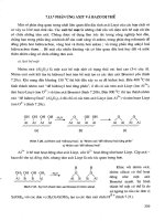
Figure 9.4 Morse signalling by hand flags or arms.
A Receiving Station – In Answer
On receiving the call-up signal the receiver should answer the call by the
answer signal – TTTTT. Should a receiving station be unable to
communicate by this method, the signal YS1 should be displayed by any
available means, meaning ‘I am unable to communicate by morse signalling
by hand-flags or arms’.
Completing the Signal
All signals are completed by the transmission of the ending signal – AR.
This method of signalling can be carried out by flags or just by the
operator’s arms, and if the operator has only one arm available, the
system is still feasible. But it is tiring and time-consuming, and unpopular
with mariners.
APPENDIX
SEAMAN’S SELF-EXAMINER
The headings indicate the examinations to which the following questions
and answers are directed.
EFFICIENT DECK HAND
1. Qu. What are the natural fibre ropes called?
Ans. Manilla, hemp, sisal, coir and cotton.
2. Qu. What is the construction of log line?
Ans. Sennet laid hemp.
3. Qu. Describe hawser layed rope?
Ans. Three-stranded rope laid up left- or right-handed.
4. Qu. How would you commence a back splice in a natural fibre
rope before starting the normal tucks?
Ans. By use of a crown knot.
5. Qu. What are the main differences between the construction of
a flexible steel wire rope and a non-flexible steel wire
rope?
Ans. A flexible wire will have more wires per strand and a fibre
heart running through the centre. Non-flexible wires do
not possess the fibre heart and have less wires per strand.
6. Qu. What is the difference between a ‘hard eye’ and a ‘soft eye’,
when splicing?
Ans. A hard eye will have a thimble spliced into the rope or wire,
and a soft eye will just be the rope or wire spliced to itself.
7. Qu. What would you expect to find stamped on the binding of
a metal block?
Ans. The safe working load of the block and the block’s certificate
number.
8. Qu. What would you use to mouse a shackle?
Ans. Seizing wire.
9. Qu. How would you make a ‘temporary eye’ in the end of a
rope?
Ans. By means of a bowline.
265Seaman’s Self-Examiner
10. Qu. What is the length of a ‘shackle of cable’?
Ans. 15 fathoms or 90 ft.
11. Qu. Where would you expect to find a ‘monkey’s fist’?
Ans. In the end of a heaving line to weight the end when
throwing.
12. Qu. How would you secure a bosun’s chair to a gantline, prior
to working aloft?
Ans. By use of a double sheetbend.
13. Qu. With what tool would you open up the lay of a rope when
splicing? Explain why a marline spike would not be used.
Ans. A wood ‘fid’ is used for splicing ropes. If a marline spike
was employed, the fibres of the rope would be cut against
the metal tip of the spike, which would considerably weaken
the finished splice.
14. Qu. When coming to a single anchor with your vessel what
would you consider to be good holding ground for the
anchor?
Ans. Mud, clay or hard sand are all considered to be good holding
grounds.
15. Qu. When worming, parcelling and serving, why would you
not use marline for the operation of ‘worming’?
Ans. Marline will not compress under the parcelling and an
uneven finish would result.
16. Qu. How would you join two wire hawsers together for the
purpose of ‘towing’, without eye splicing one to another?
Ans. Secure both hawsers by means of a ‘carrick bend’.
When towing, the hawsers could be expected to take a
considerable amount of weight. Allow the weight to be
taken up first, before seizing the tails down to the standing
parts, or the seizings may be pulled adrift.
17. Qu. What are the main functions and purpose of locking bars
when battening down conventional hatches?
Ans. The locking bars prevent the tarpaulins from blowing off
in the wind. They also act to retain the hatch boards (wood)
from floating off should the hatch become full of water.
Locking bars may also be considered an anti-theft device.
18. Qu. What is the safe working angle between the two cargo
runners considered to be, when working union purchase?
Ans. The safe working angle between the runners is 90°. The
rig can also work up to 120° without incurring excessive
stress for the occasional lift.
19. Qu. Where would you expect to find the ‘bitter end’ aboard a
vessel?
Ans. In the chain cable locker. The ‘bitter end’ is the very end of
the cable secured in or just outside the chain locker.
20. Qu. If a tackle was rove to advantage, would you be pulling on
the downhaul from the standing or from the moving block?
Ans. From the moving block.
266 Seamanship Techniques
21. Qu. When would you encounter a ‘union plate’, sometimes
referred to as a monkey face plate?
Ans. When handling derricks. The union plate connects the bull
wire chain preventer and the single span topping lift at one
point.
22. Qu. What is the function of tank top ceiling, and in what type
of vessel would you expect to encounter it?
Ans. The tank top ceiling is a wooden sheathing to protect the
tank top of the double bottom. It is normally found in
general cargo vessels situated in way of the hatchway, at the
bottom of the hold. Not only will it afford protection from
heavy loads, but, depending on its design, it may well assist
in drainage and ventilation of cargoes.
23. Qu. How could a bottle screw (turnbuckle) be locked and
secured?
Ans. (a) By means of an adjustable locking bar.
(b) By means of locking nuts on to the screw threads.
(c) By means of seizing wire turned about through the
centre and the end eyes.
24. Qu. Give an example of when a ‘solid thimble’ would be
employed, and state why you would use it as opposed, say,
to an open heart thimble?
Ans. A solid thimble is used in ‘standing rigging’, e.g. stays,
shrouds. The rigid securing when the solid thimble is
employed resists any movement of the bolt of the securing
shackle.
25. Qu. What prevents the lead pellet which retains in the spile pin
of a ‘Kenter Lugless Joining Shackle’ from falling out?
Ans. The lead pellet is inserted over the spile pin into a ‘dove tail
recess’, which prevents the pellet from coming adrift
accidentally.
CERTIFICATE OF PROFICIENCY IN SURVIVAL CRAFT AND RESCUE BOATS
1. Qu. What types of wooden-built lifeboats do you know?
Ans. Clinker, carvel and double diagonal.
2. Qu. How many boathooks are required in lifeboats?
Ans. Two.
3. Qu. Where would you find the ‘garboard strake’?
Ans. It is the first strake outward from the keel.
4. Qu. How long are the painters of a ship’s lifeboat?
Ans. As long as necessary to allow the boat to be safely launched
at lightest seagoing draught.
5. Qu. What pyrotechnics would you expect to find in the lifeboat?
Ans. Six hand held flares, four rocket parachute flares and two
orange smoke floats.
6. Qu. How would you recognise the ‘steering oar’ in a ship’s
lifeboat?
267Seaman’s Self-Examiner
Ans. The blade of the oar would be painted a distinctive colour.
The blade should also be facing aft. The steering oar is also
approximately 12 to 14 in. longer than other oars.
7. Qu. If you were the cox’n of the only motorised survival craft
to be launched after a disaster, what would be your major
function.
Ans. Collect and assemble all other survival craft. This would
enable a roll call to be made of known survivors. The
action would also provide a larger target for rescue craft to
see. One of the other craft may have an emergency radio
and in any event life support systems can be jointly used
for the survival of all.
8. Qu. How would you take a reef in lifeboat sails?
Ans. Down helm, head the boat into the wind, and let fly the
sheets. Stream the sea anchor to keep to boat’s head up
wind. Lower the yard and lay it on to the side benches of
the boat. Clear the foot of the sail. Secure the luff and leach
earrings, respectively to the tack and clew cringles.
Commence to secure the reef points about the bunched
sail, starting to tie the reef knots from the forward end to
aft. Secure the yard strop to the traveller and reset the sails.
Trip the sea anchor and resume course.
9. Qu. How long is the tripping line of the sea anchor found in
the ship’s lifeboats?
Ans. About 2 fathoms longer than the sea anchor hawser.
10. Qu. Of what construction would you expect wire lifeboat falls
to be. How often would you expect them to be renewed?
Ans. Extra flexible steel wire rope (6 × 36 or 17 × 7) wps. To be
renewed whenever required, and at no greater than at a
five-yearly interval.
11. Qu. What is the purpose of the ‘tricing-in pennants’ on the
davits of lifeboats?
Ans. The tricing-in pennants are secured to bring the boat
alongside the embarkation deck particularly when the mother
vessel has an adverse list.
12. Qu. What types of life raft are popularly employed in the marine
industry?
Ans. The rigid raft, the inflatable raft, and the davit-launched
raft.
13. Qu. What is the standard length of painter fitted to an inflatable
life raft? Can this length ever differ?
Ans. The standard length is 25 m (80 ft). This length can be
increased by order to the manufacturer if so desired, e.g. for
high freeboard vessels.
14. Qu. Three life rafts are located together. Would you attempt to
join up the rafts and if so at what distance would you
connect them together?
Ans. Yes, you would under normal circumstances join the rafts
268 Seamanship Techniques
together. They should be secured as far apart as possible so
as to avoid the painters snatching and parting when in any
sea and/or swell.
15. Qu. What is the release gear for the davit-launched life raft
called, i.e. the gear found at the end of the fall above the
raft?
Ans. Mills Atlas Release Gear.
16. Qu. At what angle of adverse list must a davit-launched raft be
capable of being launched?
Ans. 20° of adverse list.
17. Qu. How would you attempt to beach a life raft?
Ans. As follows, during the hours of daylight and on a gently
sloping beach, if circumstances permit:
(a) Inflate the floor of the raft.
(b) Stream both sea anchors (drogues).
(c) Open up the entrances and man the paddles.
(d) See that all personnel are wearing lifejackets.
18. Qu. When in a life raft, what would you use the two sponges
for?
Ans. One sponge should be used after the bailing to dry the
inside floor area of the raft. The other sponge should be
used to collect condensation from the inside canopy for
drinking use.
19. Qu. What is the breaking strain of the weak link of the hydrostatic
release system?
Ans. 500 lb ± 100 lb or 227 kg ± 45 kg.
20. Qu. After a raft has been launched, how would you get it away
from the ship’s side?
Ans. Cut the painter, and use both paddles. If the raft is of a
circular design, use of the paddles may prove difficult. In
that case use them in conjunction with a heavy object
placed in the sea anchor: throw the sea anchor at right-
angles to the fore and aft line of the vessel, then pull the
raft towards the sea anchor.
21. Qu. What markings would you expect to find on the outside
canister of an inflatable life raft?
Ans. The maker’s name, an indication as to the top of the canister,
the capacity of the raft (number of persons to be carried),
the length of painter, date of last service, date of next
service, statement whether raft complies with SOLAS
regulations, instructions for launching, do not roll symbol
if fitted with aerial facility.
22. Qu. How often are life rafts and hydrostatic release units surveyed
and by whom?
Ans. Every twelve months by a Department of Trade approved
agency.
23. Qu. What is the emergency boat muster signal?
Ans. Seven or more short blasts on the ship’s bells and whistles,
followed by a continuous long ringing/sounding of each.
PART TWO
SHIP HANDLING
CONTENTS TO PART TWO
Acknowledgments vii
List of plates ix
List of tables xi
1. WATCHKEEPING DUTIES
Master’s responsibilities 1
Watchkeeping – general duties 3
Duties of the officer of the watch (OOW) 3
Duties of the lookout 5
Duties of the helmsman 6
Duties of the standby man 7
Official publications 9
Rigging pilot ladders 15
Mechanical pilot hoists 17
Ship to shore transit 20
2. SPEED AND DEPTH
Patent rotator log 21
Impeller log 24
Hand lead 25
Echo-sounding 26
3. MARINE INSTRUMENTS
Sextant 30
Marine chronometer 35
The gyro compass 36
Magnetic compass 41
Liquid magnetic compass 42
Dry card magnetic compass 48
Azimuth mirror 49
Pelorus 50
Hydrometer 52
Hygrometer 53
Precision aneroid barometer 53
4. METEOROLOGY
Meteorological terms 57
Forecast areas 65
Weather scales 65
Construction and interpretation of synoptic chart 66
Contingency plans for heavy weather 69
Effects of heavy weather on vessel at sea 71
General behaviour of vessels in heavy weather 72
Tropical revolving storm 76
Ice terminology 78
Ice navigation 83
5. PREVENTING COLLISIONS AT SEA
International regulations 86
Judging another vessel’s heading at night 124
Special cases to rule of the road 125
Rule of the road – questions and answers 129
IALA maritime buoyage systems ‘A’ and ‘B’ 132
6. EMERGENCIES
Collision 137
Flooding 139
Abandonment from the vessel 141
Rescue and recovery of survivors 143
Stranding 145
Breaching procedure 145
Deck department checklist for watertight integrity of hull
following grounding or beaching 147
Engine room department checklist for machinery spaces
following grounding or beaching 147
Watertight doors 148
Drydock procedure 150
Man overboard 153
Helicopter procedure 156
Steering gear failure or loss of rudder 161
Subsunk, procedure 164
7. FIRE-FIGHTING
Small fires 166
Accommodation fires at sea 168
Galley fires at sea 169
Machinery space fires at sea 171
Cargo space fires at sea and in port 174
Paint room fires 177
Fixed fire-fighting installations 178
iv Contents to Part Two
International shore connection 183
Self-contained breathing apparatus 183
Example: Cargo fires 185
8. SEARCH AND RESCUE OPERATIONS
Action by vessel in distress 189
Master’s obligations 190
Obligations of rescuing craft 190
When assistance is no longer required 191
Searching the sea 191
Aircraft in distress 192
Communications between surface craft and aircraft 192
Surface to surface rescue 193
Pyrotechnics 196
Breeches buoy 200
Communications 203
HM Coastguard 204
AMVER organisation 207
Abbreviations 209
9. SHIP-HANDLING
Terms and general definitions 210
Factors in ship-handling 212
Rudders 213
Propellers 215
Turning circles 219
Bow/stern thruster units 223
Fin stabilisers 225
Manoeuvring with mooring lines 227
Fairleads 227
Bollard (bitts) 227
Rigging slip wires or ropes 228
Berthing 230
Clearing a berth 230
Entering dock 232
Securing to buoys 232
Mooring 233
Letting go from buoys 233
Turning vessel short round 234
Open moor 236
Interaction 240
Shallow water effects and squat 241
Working with tugs 242
10. TANKER WORK AND OIL POLLUTION
Tanker vessels 249
Tanker hazard and precautions 250
Dangers of petroleum spirit 252
vContents to Part Two
General definitions 254
Cargo-handling equipment 255
Whessoe tank gauge 257
General operations and procedures 258
Tanker layout and ventilation 261
Health and safety 261
Inert gas system 269
Mooring large tankers 274
Oil pollution 276
Appendix to Chapter 10 287
Appendix: Seaman’s self-examiner
Officer of Watch Certificate (OOW) 289
Class 2 Certificate of Competency (Oral) 292
Certificate of Competency for Master Mariner, Class 1 297
Index to Part One 309
Index to Part Two 317
vi Contents to Part Two
Stanford Maritime Ltd., for references from Tugs by Captain Armi-
tage and from Basic Shiphandling for Masters
& Mates, by P.F. Willerton
The Motor Ship (published by IPC Industrial Press Ltd)
Schilling Rudders
F.R. Hughes & Co., Ltd
viii Acknowledgments to Part Two
29. Vessel moored at quayside 234
30. Cruise ship moored 237
31. Gob rope on tug 244
32. Alternative type of gob rope 245
33. Bow section showing Panama Lead 248
x Plates to Part Two
2 Seamanship Techniques
1. Modern wide bridge design. A Minerva fire-detection
unit may be seen on the after bulkhead opposite the
control console.
The Master should further be aware that the protection of the marine
environment is a major consideration. He should take all necessary
precautions to ensure that no operational or accidental pollution of the
environment takes place, being guided in this matter by the existing
international regulations.
Checklist of Items for Passage Appraisal
1. Select largest scale appropriate charts for the passage.
2. Check that all charts to be used have been brought up to date from
the latest information available.
3. Check that all radio navigational warnings affecting the area have
been received.
4. Check that sailing directions and relevant lists of lights have been
brought up to date.
5. Estimate the draught of the ship during the various stages of the
passage.
6. Study sailing directions for advice and recommendations on route
to be taken.
7. Consult current atlas to obtain direction and rate of set.
8. Consult tide tables and tidal atlas to obtain times, heights and
direction and rate of set.
9. Study climatological information for weather characteristics of the
area.
10. Study charted navigational aids and coastline characteristics for
landfall and position monitoring purposes.
11. Check the requirements of traffic separation and routeing schemes.
12. Consider volume and flow of traffic likely to be encountered.
4 Seamanship Techniques
*Further reading: IMO Recommendations on Navigational Watchkeeping.
2. Radar reflector unit.
radar, additional manpower, helmsman, or anything else considered necessary
for the safety of the vessel.*
The OOW should make full use of navigational aids such as echo-
sounder, whenever possible to check navigational accuracy. Radar plotting
should be carried out in good weather as well as in foul to ensure that
the mariner becomes proficient in the correct plotting techniques.
Any watch officer should also be aware of the ship’s capabilities in the
way of ‘turning circles’ and emergency stop distances. He should not
hesitate to summon the Master at any time, day or night, should he
require assistance. In any event the Master should be kept informed by
the officer of the watch of all the movements and events affecting the
vessel’s progress.
Calling the Master
The officer of the watch should notify the Master immediately in the
following circumstances:
(a) If restricted visibility is encountered or suspected.
(b) If the traffic conditions or the movements of other vessels are
causing concern.
(c) If difficulty is experienced in maintaining course.
(d ) On failure to sight land or navigation mark, or to obtain soundings
by the expected time.
(e) If land or navigation mark is sighted or a change of soundings
occurs unexpectedly.
8 Seamanship Techniques
TABLE 1.1 Example of helm orders
Order (by OOW, Helmsman’s reply Helmsman’s actions Helmsman’s final
Pilot or Master) report
Starboard twenty Starboard twenty, Turns the wheel until Twenty degrees
degrees sir twenty degrees to of starboard helm
starboard is shown by ‘on’, sir
the rudder indicator
Midships Midships, sir Returns the wheel to Wheel amidships,
the midships position. sir
Checks that rudder
indicator shows
midships
Hard a-port Hard a-port, sir Turns the wheel as Wheel hard a-
far to port as it will port, sir
go. Checks that
rudder indicator
shows maximum port
helm
Ease the wheel to Ease the wheel to Allows the wheel to Wheel eased to
port ten degrees port ten degrees, return towards the port ten degrees,
sir midships position, sir
but retains ten
degrees of port helm
as shown by rudder
indicator
Check her (should Check her, sir Turns the wheel
be understood to against the swing of
mean, check the the vessel, up to
swing of the approx. ten degrees
vessel) of opposing helm
being applied to
reduce the rate of
swing. Eases the
wheel back to the
midships position
once the vessel stops
swinging
Steady Steady, sir Observes compass Steady on course,
heading, or land X, Y, Z (or
reference point, and whatever the
steadies the ship’s heading happens
head in/on that to be)
heading. Applies
helm as required in
order to maintain a
steady course
The supervising officer may, in addition, use the following phrases:
‘How is your head?’, a question as to the ship’s compass heading.
‘Alter course to . . .’, ordering the helmsman to apply helm to change the ship’s course to
whatever is stated.
‘State when the vessel stops steering’, or when vessel no longer responds to helm movement
because she has reduced her way, i.e. helm hard a-port and the vessel paying off to
starboard.
‘Finished with the wheel’, when the helmsman is no longer required. The wheel is returned
to midships and the helmsman can stand down.
10 Seamanship Techniques
A copy of Chart Abbreviations (No. 5011),
IAMSAR Manual
A copy of Ship Routeing and Traffic Separation Schemes,
A Ship Master’s Medical Guide,
Stability Information Booklet,
Relevant Statutory Instruments,
and if relevant to the trade,
Code of Safe Working Practice for Bulk Cargoes,
Manual on the Avoidance of Oil Pollution,
Tanker Safety Guide.
Other countries, especially those which comply with IMO conventions,
have similar rules for the carriage of official publications. The only
difference is that their titles may differ from the British ones.
Official Publications in Detail
Weekly Notices to Mariners
These are published by the Hydrographic Department of the Admiralty
in booklet form. They contain an index to all the navigational corrections
included in the booklet for that week, together with temporary (T) and
preliminary (P) notices regarding navigational corrections. At the end of
the booklet there are sections giving corrections to the Admiralty List of
Radio Signals, and the Admiralty List of Lights. Information regarding new
charts, new editions, and large and small corrections to charts are all
included in the weekly list.
Annual Summary of Admiralty Notices to Mariners
This publication, is issued annually by the Hydrographic Department of
the Admiralty. The notices contain information on such items as tide
table corrections, list of agents for charts, radio message procedures,
search and rescue operational details, firing and practice areas, submarine
information, coastal radio warning stations, minelaying operations etc.,
ocean weather ship details, and navigational warnings. The Annual Summary
and the Weekly Notices to Mariners, are obtainable from any of the mercantile
marine offices, chart agents and custom offices.
Merchant Shipping Notices (‘M’ Notices)
These are published by the Marine Safety Agency and from 1997 known
and titled as MSN’s. They convey mandatory information which must be
complied with under United Kingdom law. They amplify and expand on
Statutory instruments. In addition, Marine Guidance Notes (MGNs)
will be issued regarding specific topic areas, e.g. SOLAS, MARPOL etc.,’
also Marine Information Notes (MINs) will be issued aimed at training
establishments, equipment manufacturers etc. These will be published
periodically and will also carry a self cancellation date.
NB. Each of the above notices will be pre-fixed by:
(M) for Merchant Vessels
(N) for Fishing Vessels
(M+F) for both Merchant and Fishing Vessels.
11Watchkeeping Duties
Mariners Handbook
This handbook was first published in 1962 by the Hydrographer of the
Royal Navy. It has since been reissued seven times, the last time in 1999.
The Handbook is a reference book for mariners, giving information with
regard to the following: charts and publications, the use of navigational
aids, navigational hazards, natural conditions pertinent to weather, ice
navigation and various tables of conversion factors.
Admiralty List of Radio Signals
These comprise eight volumes published by the Admiralty which contain
details of individual radio stations and the services they provide, and
information with regard to radio procedures, together with extracts of
regulations governing transmission and reception of radio signals. The
volumes cover all areas and provide information to operators regarding
navigational warnings, time signals, medical advice, weather bulletins,
satellite information and distress procedures.
Admiralty List of Lights
This is a publication in several volumes which lists the characteristics of
all navigation lights and beacons. The lights are geographically listed to
allow a prudent navigator to achieve continuity and easy comparison
from the coastline against the listing. Information on each light includes
the position of the light, the name of the light, its range and any flashing
characteristic.
Admiralty Sailing Directions
Often referred to as ‘Pilot Books’, covering the whole world, they are
published by the Admiralty in over 70 volumes. Each volume provides
the mariner with general information and local knowledge of the area in
which he intends to navigate. Items are covered in detail including port
facilities, navigational hazards regarding port entry, systems of buoyage,
coastline views and chart information.
Admiralty Tide Tables
Published by the Hydrographic Department of the Navy, these are tidal
predictions for all ‘standard’ and ‘secondary’ ports. They are published in
three volumes:
Volume I, covers Europen waters, including the Mediterranean.
Volume II, covers the Indian and Atlantic Oceans.
Volume III, covers the Pacific Ocean and adjacent seas.
The tables provide the time and the heights of high and low waters for
the ‘standard’ port on a daily basis. In the second part of the volumes the
details for ‘secondary’ ports can be calculated by making minor adjust-
ment to the heights and times of tides at the nearest ‘standard’ port.
12 Seamanship Techniques
Nautical Almanac
This is a book of information relating to the sun, planets, moon and stars,
published jointly by HM Nautical Almanac Office and the US Naval
Observatory. The listing provides information with regard to Greenwich
hour angle, meridian passage, sidereal hour angle etc. of celestial bodies.
The listed information is required in the calculations made to ascertain
the ship’s position by observing heavenly bodies.
There are a number of publishers of nautical almanacs at present in
the commercial field. The almanacs are published annually and should
be collected well in advance for vessels engaged on long voyages which
may run into the following year.
Nautical Tables
Every vessel is obliged to carry a set of these tables in order to carry out
the basic navigational functions. Each set will contain computation tables
of logarithms, traverse tables, square roots etc. together with tables for
celestial navigation: A, B, and C tables, amplitude corrections, total correction
tables etc. Additional tables cover coastal navigation, day’s run, radar
range, distance by vertical angle etc.
Several publishers are engaged in the distribution of nautical tables.
The most popular are probably Norie’s Nautical Tables and Burtons Nautical
Tables.
Oil Record Book
This book’s purpose is to record all oil movements aboard the vessel. It
is carried by tanker vessels and vessels other than tankers. All entries
should bear the signature of the Master of the vessel, together with those
of officers concerned in the movement of oils or oily waste. A copy of
the entries made into the oil record book for a non-tanker type vessel is
given in Table 1.3.
International Code of Signals
Published by Her Majesty’s Stationery Office, it is used for coding and
decoding signals made by international signal flags. It also contains
information on methods of marine communication and procedures for
their execution. (See Part One, Chapter 9, ‘Communications’.)
Tidal Stream Atlas
This contains detailed plans of the British Isles and other selected areas
showing the state of the tide at hourly intervals either side of high water.
Indication of the tidal flow is shown by arrows referring to times and
state of tide at a major port, e.g. ‘Dover, High Water’. By comparing the
ship’s position and the time to the time of high water at a particular port,
the navigator can ascertain the state of the tide in relation to the ship.
13Watchkeeping Duties
TABLE 1.3 Entries in oil record book for ships other than tankers
(a) Ballasting or cleaning of bunker fuel tanks
1. Identity of tank(s) ballasted
2. Whether cleaned since last containing oil and if not, type of oil previously
carried
3. Date and position of ship at start of cleaning
4. Date and position of ship at start of ballasting
(b) Discharge of dirty ballast or cleaning water from tanks referred to under (a)
5. Identity of tank(s)
6. Date and position of ship at start of discharge
7. Date and position of ship at finish of discharge
8. Ship’s speed(s) during discharge
9. Method of discharge (state whether separator was used)
10. Quantity discharged
Signature of officer or officers in charge of the operations and date.
Signature of Master and date.
(c) Disposal of residues
11. Quantity of residue retained on board
12. Methods of disposal of residue:
(a) reception facilities
(b) mixed with next bunkering
(c) transferred to another (other) tank(s)
13. Date and port of disposal of residue*
Signature of officer or officers in charge of the operations and date.
Signature of Master and date.
(d) Discharge of oily bilge water which has accumulated in machinery spaces whilst in port
14. Port
15. Duration of stay
16. Quantity disposed
17. Date and place of disposal
18. Method of disposal (state whether separator was used)
(e) Routine discharge at sea of oily bilge water from machinery spaces*
19. Frequency of discharge and method of disposal
(state whether or not a separator was used)*†
Signature of officer or officers in charge of the operations and date.
Signature of Master and date.
( f ) Accidental or other exceptional discharge of oil.
20. Date and time of occurrence
21. Place or position of ship at time of occurrence
22. Approximate quantity and type of oil
23. Circumstances of discharge or escape and general remarks
Signature of officer or officers reporting the occurrence and date.
Signature of Master and date.
* In accordance with regulations such discharges need not be entered into this book if
entered in the engine room log book.
† Where pumps start automatically and discharge through a separator at all times, it will be
sufficient to enter each day, ‘Automatic discharge from bilges through separator’.
14 Seamanship Techniques
Code of Safe Working Practice
A recent publication by Her Majesty’s Stationery Office on behalf of the
Maritime and Coastguard Agency, this details safe working practice for
seamen in all departments of the ship. It covers deck work, engine room
practice, electrical apparatus etc. together with working practices in and
around the galley and catering department.
IMDG Code
Mariners are guided by rules and recommendations regarding the carriage
of dangerous goods at sea, and these rules and recommendations are
contained in what is known as The International Maritime Dangerous Goods
(IMDG) Code. This publication has now replaced what was previously
known as The Blue Book. It is published by the IMO and is directly
concerned with the recommendations relevant to the carriage of dangerous
substances. It specifies in detail the method of stowage and packaging of
dangerous cargoes.
It is contained in five volumes and provides relevant information on
the required documentation and respective class of cargoes.
Shippers are required under the Merchant Shipping (Dangerous Goods)
Rules to provide a certificate stating that the goods are properly marked,
labelled and packaged in accordance with the rules. The goods are classified
as follows:
Class 1. Explosives.
Class 2. Flammable gases, poisonous gases, or compressed, liquefied or
dissolved gases which are neither flammable nor poisonous.
Class 3. Flammable liquids sub-divided into three categories:
3.1 Low flashpoint group of liquids having a flashpoint below –18°C
(0°F) closed cup test, or having a low flashpoint in combination
with some dangerous property other than flammability.
3.2 Intermediate flashpoint group of liquids having a flashpoint of
–18°C (0°F) up to but not including 23°C (73°F) closed cup test.
3.3 High flashpoint group liquids having a flashpoint of 23°C (73°F)
up to and including 61°C (141°F) closed cup test.
Class 4.
4.1 Flammable solids.
4.2 Flammable solids or substances liable to spontaneous combustion.
4.3 Flammable solids or substances which in contact with water emit
flammable gases.
Class 5.
5.1 Oxidising substances.
5.2 Organic peroxides.
Class 6.
6.1 Poisonous (toxic) substances.
6.2 Infectious substances.
Class 7. Radioactive substances.
Class 8. Corrosives.
Class 9. Miscellaneous dangerous substances, that is any other sub-stance
16 Seamanship Techniques
must be by means of an accommodation ladder or other equally safe
means (Figure 1.3).
The treads of the ladder must be made of a hard wood such as ash,
oak, elm or teak. Each step must be made from a piece free of knots,
having a non-slip surface; and must be not less than 480 mm long, 115
mm wide and 25 mm in depth. The steps should be spaced not less than
300 mm nor more than 380 mm apart, and individually secured in such
a manner that they will remain horizontal. The four lower steps may be
constructed in rubber or other suitable material of sufficient strength
and similar character. No pilot ladder must have more than two replacement
steps secured in a different manner from the original method of securing,
and these must be secured in place by the original method as soon as
possible.
The side ropes of the ladder must consist of manilla rope 18 mm in
diameter. Each rope must be continuous without joins and should be left
uncovered. Manropes of not less than 20 mm in diameter should be
secured to the ship, and a safety line kept ready for use if required.
Hard wood battens (spreaders or anti-twist battens) between 1800
and 2000 mm long must be provided at such intervals as will prevent the
pilot ladder from twisting. They must be so fixed that the lowest batten
comes no lower than the fifth step from the bottom, and the interval
between battens must not be more than nine steps. Each batten must be
made of ash, oak or similar material, free of knots.
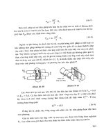
To davit and
winch
Promenade deck
Yoke
Sheave
Freeboard
deck
Platform support
Accommodation ladder
Spreader
Pilot ladder
Water level
Chain
bridle
Pilot ladder
tails
Figure 1.3 Combined rigging of accommodation and
pilot ladders.
18 Seamanship Techniques
Falls
The two separate flexible steel wire rope falls should be resistant to
corrosion in a salt-laden atmosphere. They should be securely attached
to the winch drums and the ladder by fitments capable of withstanding
a proof load of not less then 2.2 times the load on such fitments. The
length of the falls should be sufficient to allow at least three turns to be
retained on the winch drum when the hoist is in the lowest position, at
all levels of freeboard.
Ladder Sections
The rigid section should be not less than 2.5 m in length and arranged so
that the pilot may take up a safe position while being hoisted. It should
be provided with adequate means of communication between the pilot
and the hoist operator, together with an emergency stop control within
easy reach of the pilot.
The section should be fitted at the lower end with a spreader not less
than 1.8 m in length. The ends of the spreader should be provided with
rollers which will allow the section to roll freely on the ship’s side during
the operation of embarking and disembarking pilots. A sufficient number
of steps with non-skid surfaces should be included in the section to
facilitate safe and easy access to the deck of the vessel.
The section should also be provided with suitable handholds, which
will protect operators’ hands from extreme temperatures and provide a
safe secure hold. In addition, it needs an effective guard ring, well padded
to support the pilot without hampering his movements.
The flexible section consists of a pilot ladder length of eight steps.
Manufactured in hard wood, it should be free of knots like the conventional
pilot ladder, and of the same size.
Both the rigid and the flexible sections should be in the same vertical
line, be of the same width and placed as near to the ship’s side as
practicable. Both sections should be so secured that the handholds are
also aligned as closely as possible.
Testing of New Hoists
All new pilot hoist systems are subjected to an overload test of 2.2 times
the working load. During the test the load should be lowered a distance
of not less than 5 m, the weight of each person being taken as 150 kg.
After installation has been completed, a 10 per cent overload test
should be carried out to check securing attachments. Regular test rigging
and inspection should be carried out by ships’ personnel at intervals not
exceeding six months and a record of these checks maintained by the
Master in the ship’s log. Subsequent examinations of the hoists, under
working conditions, should be made for each survey for the vessel’s
Safety Equipment Certificate.
Rigging and Operational Aspects
Before use, the rigging of the hoist should be supervised by a responsible