Radio Propagation and Remote Sensing of the Environment - Chapter 11 ppsx
Bạn đang xem bản rút gọn của tài liệu. Xem và tải ngay bản đầy đủ của tài liệu tại đây (4.15 MB, 32 trang )
© 2005 by CRC Press
303
11
Radio Devices for
Remote Sensing
Two classes of devices and corresponding methods are used for remote sensing of
the environment. Devices that radiate radiowaves and receive them after their inter-
action with media belong to the first class and are referred to as the active devices.
Devices of the second class, as a rule, receive intrinsic thermal radiation of natural
objects and are referred to as passive devices. The different types of radars, altim-
eters, scatterometers, and radio occultation instruments are examples of active
devices. The different types of microwave radiometers are classified as the passive
devices.
11.1 SOME CHARACTERISTICS OF ANTENNA SYSTEMS
All radio devices for remote sensing are equipped with antenna systems for the
reception of radiowaves (and for their radiation, in the case of active instruments).
This is the reason why we will consider again the properties of an antenna. We have
directivity and pattern . The definition of directivity was based on
the angular distribution of the radiated power relative to the power at the antenna
input. The energy losses (e.g., taking place in the feeding systems) were not taken
into consideration; therefore, we need to include in our analysis the antenna effi-
ciency:
, (11.1)
which reflects the ratio of radiated power
P
i
to input power
P
t
. So, the gain,
, often figures into engineering computations.
The effective area of the antenna was used to characterize the receiving properties
of the antenna. Normally, this notion relates to the geometrical antenna area via the
aperture efficiency :
. (11.2)
D(, )θϕ Ψ(, )θϕ
η =
P
P
i
t
GD(, ) (, )θϕ η θϕ=
η
a
e
A
A
=
max
TF1710_book.fm Page 303 Thursday, September 30, 2004 1:43 PM
established already in the Chapter 1 that transmitting antenna are characterized by
© 2005 by CRC Press
304
Radio Propagation and Remote Sensing of the Environment
Here, the maximum effective area occurs in the numerator. Equation (1.114) helps
us to define the aperture efficiency as:
. (11.3)
The normalized amplitude of the aperture field (the apparatus function
F
(r
′
)) is
substituted here for the field. The utilization factor is equal to unity in the case of
a uniform aperture field distribution (the apparatus function equals unity). In this
case, the antenna pattern of the circular antenna can be written as shown in Equation
(1.118). We must point out that a uniform distribution is an idealization of practical
situations. In reality, the utilization factor is less than unity.
The side lobes of both kinds of antennae (transmitting and receiving) are of
interest, as very often they are sources of interference. One of the main reasons for
the high side lobe level is the sharp change of apparatus function at the edge of the
antenna; therefore, uniform apparatus function leads to a high level of the side lobes.
The first side lobe of the circular antenna, in this case, is 17.6 dB less compared to
the major one; therefore, in order to lower this level, we want the apparatus function
at the edge of the antenna to tend to zero. As a modeling example, we can choose
the apparatus function for the circular antenna in the view . The
antenna pattern will be:
, (11.4)
and the first side lobe level will be 24.6 dB;
4
however, in this case, the beamwidth
is whereas it is for the uniform apparatus function. The utilization
factor is 0.75.
4
The stray factor:
(11.5)
is applied for the side lobe role general assessment. Here,
Ω
0
is the solid angle of
the major lobe estimated by the first zero line of the antenna pattern. In the case of
the patterns represented by Equation (1.118), it is reduced to , where
is the second root of the first-order Bessel function, and we have the
η
a
A
A
Fd
AF d
=
′
()
′
′
()
′
∫
∫
r
r
2
2
2
2
r
r
Fa() ( )rr= −1
2
Ψθ
θ
θ
()
=
()
()
4
2
2
4
Jka
ka
sin
sin
064. λ a 051. λ a
β
θϕ
θϕ
π
= −
∫∫
∫∫
1
0
4
Fd
Fd
n
n
(, )
(, )
Ω
Ω
Ω
β = Jj
0
2
12
()
,
j
12,
TF1710_book.fm Page 304 Thursday, September 30, 2004 1:43 PM
© 2005 by CRC Press
Radio Devices for Remote Sensing
305
corresponding quantity . This value is defined by a similar formula as in
Equation (11.4), except that in this case the root of the second-order Bessel function
will be the zero-order function argument
j
2,2
= 5.136 and
β
= 0.017.
The level of the side lobes, as a rule, is not very important for radar. More
important is the signal-to-noise ratio; therefore, the standard approach is to have
maximal aperture efficiency and, correspondingly, maximum directivity. For radi-
ometry, however, a low level of side lobes is one of the most important parameters.
So, we may have to sacrifice sensitivity due to some deterioration of the spatial
resolution.
11.2 APPLICATION OF RADAR DEVICES FOR
ENVIRONMENTAL RESEARCH
Radar devices for remote sensing of the environment are mounted on the surface of
the Earth, on ships and riverboats, and on air- and spacecraft. Earth-mounted radar
is used for the study of the atmosphere and ionosphere and to observe coastal sea
zones and inland reservoirs, as well as various types of land and the structure of the
surface layers. Ship radar is used mostly for water surface monitoring and atmos-
pheric research, as well as coastal area supervision. All elements of the environment
are the objects of observation for air- and spaceborne radars.
The main purposes of such research are analysis of radiowave intensity and
polarization, the study of the shape and time delay of signals, etc. These data are
used for radar mapping, altimetry, scatterometric research, and subsurface sounding.
The main areas of application are geology (e.g., structure and lithology), hydrology
(e.g., determining soil moisture; mapping river basins, inner reservoirs, floods, snow-
cover), farming (e.g., mapping crops, monitoring vegetation growth and maturation,
determining field borders, observing soil moisture dynamics), forestry (e.g., estimat-
ing merchantable wood, monitoring deforestation, detecting forest fires, assessing
fire hazard situations), oceanology (e.g., sea-wave zone monitoring, measuring near-
water wind velocity, determining the direction in which a pollution area is moving,
studying sea currents and geoid forms), atmospheric research (e.g., sounding clouds
and rain areas, determining temperature height profiles, defining atmospheric turbu-
lence, detecting minor gaseous constituents), study of ionospheric dynamics (e.g.,
altitude profiles of electron concentrations, turbulence motion, electron and ion
temperature measurement), cartography (e.g., topographical survey of regions that
are difficult to access, land use mapping), polar area observations (e.g., monitoring
and investigating sea ice, mapping continental ice covers, observing iceberg forma-
tion and their motion, researching changes in glaciers).
Generally, four types of radar devices are used for remote sensing: panoramic
radars, scatterometers, radio altimeters, and subsurface radars. Panoramic radar
involves sectoring or a circular scanning view and side-looking radar; the latter type
includes radar with a real aperture and synthetic-aperture radars (SAR). Scatterom-
eters are classified according to the methods for selecting a given area. The main
applications are angle–angle (the antenna pattern is narrow on both planes),
angle–time (the pattern is narrow only on the azimuthal plane, thus the signal is
β = 016.
TF1710_book.fm Page 305 Thursday, September 30, 2004 1:43 PM
© 2005 by CRC Press
306
Radio Propagation and Remote Sensing of the Environment
modulated by narrow pulses), angle–frequency (the pattern is narrow on the azi-
muthal plane and is directed along the platform flight line; signal discrimination is
achieved by Doppler selection), frequency–time (SAR with pulse modulation).
Altimeters are classified by the modulation method: pulse, frequency, or phase
modulation. Subsurface radars differ in where the antenna is mounted: remote or
applied (the antenna is put on the surface of the studied object).
11.3 RADIO ALTIMETERS
The radio altimeter is in theory one of the simplest radar systems. Applications of
remote sensing using radio altimeters include measuring water levels, defining geoid
forms, estimating seawave intensity, monitoring glacier growth, mapping land sur-
face topographic, determining upper cloud levels, etc. Pulse-modulated or chirp
signals are normally used for altimetric research. For the traveling time of the signal
(
t
r–t
) over the path, transmitter–surface–receiver serves as a device for measuring the
altitude of the altimeter platform above the studied surface. The common relation is:
, (11.6)
where
v
is the mean velocity of radiowave propagation in the atmosphere of Earth.
The frequency spectrum of altimetric systems is chosen in such a way that the
influence of the ionosphere is small. Usually, the C, X, and Ku-bands are preferable
for these devices.
The error in the altitude determination is:
, (11.7)
where
δ
t
r–t
and
δ
v
are errors in the delay time and mean velocity, respectively. The
first summand contribution is defined by the leading edge steepness of the optimally
processed pulse and the signal-to-noise ratio at the altimeter output. Generally,
, (11.8)
where
τ
i
is the leading edge duration after reflection (scattering), and
S/N
is the
signal-to-noise ratio.
89
Changes in the leading edge as a result of scattering by a
The second term in Equation (11.7) depends on the propagation conditions. In
the case of spaceborne altimeters, the contributions of both the troposphere and
ionosphere must be taken into account. The tropospheric contribution, corresponding
to Equation (4.57), can be written as:
H
tv
=
r-t
2
δδ δH
v
t
t
v=+
−
−
2
rt
rt
2
δ
τ
t
SN
i
rt−
=
()
2
TF1710_book.fm Page 306 Thursday, September 30, 2004 1:43 PM
rough surface are described in Chapter 6.
© 2005 by CRC Press
Radio Devices for Remote Sensing
307
(11.9)
Equation (4.69) permits us to estimate the ionospheric contribution as:
. (11.10)
For the X-band, it will be about 10 cm. For greater accuracy when defining altitude,
it is necessary to develop procedures for correcting the radio propagation. In the
case of the troposphere, atmospheric models are used. Microwave radiometers are
added to measure water vapor content, which gives us a more accurate calculation
of the mean value of the refractive index. Correcting for ionospheric influences
requires the design of a two-frequency altimeter or the use of very high frequencies,
which generates new problems (scattering by clouds, for example). In order to
overcome these, continuous analysis of signals is needed using, for example, a
strobing technique.
The accuracy of the altimeter also depends on the antenna beamwidth and its
positional stability. These effects become most apparent in the case of strong reflec-
tion from the surface edge coinciding with the footprint board. As was noted in
signal.
89
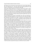
Examples of backscattered signals are given in Figure 11.1. This is one
reason why estimating the time delay using the arrival of the leading edge of the
pulse gives us a more accurate altitude measurement. Simultaneously, pulse distor-
tion analysis allows the study of the roughness parameters. In particular, this tech-
nique is used for sea waves intensity monitoring.
FIGURE 11.1
The approached pulse shape of normalized altimeter impulses: (1) salt desert;
(2) and (3), agricultural holdings; (4) surface of lake.
t
v
H
T
rt
2
m.
−
=
−
()
≅δ
ε
0
1
2
25.
t
v
f
rt
2
−
=
⋅
δ
12110
21
2
.
0.4
0.6
3
2
4
1
2
1
3
4
0.2
0
t
0.8
1
u
TF1710_book.fm Page 307 Thursday, September 30, 2004 1:43 PM
Chapter 6, surface roughness leads to a change in the duration of the scattered
© 2005 by CRC Press
308
Radio Propagation and Remote Sensing of the Environment
The first spaceborne altimeter was tested during the SKYLAB mission. It oper-
ated at a frequency of 13.9 GHz, and the pulse duration was of the order of 25 nsec.
The measurements taken showed that we can determine the topographic relief under
the satellite trace with an accuracy of ±15 meters for the case of a relatively smooth
surface without mountains and steep slopes. The altitude above a quiet water surface
could be determined with an accuracy of about ±1 meter.
89
The investigation of ocean problems requires a more accurate altimeter. Research
has shown that errors of altitude determination must be less than 10 cm. Very short
pulses are needed in this case, which explains why chirp modulation is useful in
modern altimeters. In particular, pulses with a duration of the order of 100
µ
sec and
a frequency deviation inside
∆
F
= 320 MHz are used in modern altimeters. The
compression procedure provides the altitude definition with an accuracy that is
similar to pulses of 3.1-nsec duration.
A spaceborne altimeter of very high accuracy is applied in the U.S.–French
mission TOPEX/POSEIDON, which is designed to research water surface charac-
teristics.
145
The C- and Ku-bands (frequencies of 5.3 and 13.6 GHz, respectively)
are used. The two-frequency system allows us to correct the ionospheric influences.
Microwave radiometers, operating at frequencies of 18, 21, and 37 GHz, provide
the tropospheric correction. A good system of 1.5-m antenna orientation minimizes
errors connected with main lobe deviation from the nadir. There is a system based
on the ground for the satellite coordinates determination with heightened accuracy.
A complicated procedure of corrections has been developed for altimeter data
processing and interpretation. Depending on the seawave intensity and the data
averaging time, the accuracy of the mean level of the oceanic surface definition lies
within a range of several centimeters.
11.4 RADAR SYSTEMS FOR REMOTE SENSING OF THE
ENVIRONMENT
A different type of panoramic radar is commonly used for remote sensing of the
environment. These radar systems differ in their principles of operation and in the
technique of observation. The received pulses are distinguished by arrival time,
which allows determination of the distance to the illuminated object (in the case of
monostatic radar), and amplitude, both of which allow us to define the scattering
properties (reflectivity) of this object. In this process, the direction of the antenna
major lobe is fixed, and the direction of the investigated target is determined. The
scattering properties of targets can depend on polarization of illuminated waves and
scatter the waves with a polarization different from the polarization of incident
waves. So, the polarization matrix or Stokes matrix are the subject of interest in
more complicated systems. These data open the way for mapping the scattering
properties of the environment.
The radar systems applied to remote sensing are separated roughly into two
classes: radar for atmospheric research (troposphere and ionosphere) and radar for
monitoring the surface of Earth (land and water). Ionospheric radar will be discussed
TF1710_book.fm Page 308 Thursday, September 30, 2004 1:43 PM
the targets themselves, as we saw in Chapter 5 (Section 5.6). The targets usually
© 2005 by CRC Press
Radio Devices for Remote Sensing
309
which is used primarily for the investigation of hydrometeors. Scanning space is
made possible with the help of a pencil-beam antenna. The main parameter of
measurement is the reflectivity, which is determined via the intensity of the received
pulses. The power of a signal received from a point scatterer is defined by the radar
equation:
. (11.11)
Here,
W
is the received power;
P
is the pulse transmitted power;
D
and
A
e
are the
radar antenna directivity and its effective area, respectively;
σ
is the target differential
cross section of backscattering;
L
is the distance between the radar and the target;
and
λ
is the radiowavelength. In contrast to the traditionally applied formulae, we
use the physical definition of the cross section, which is different from the radar one
by the factor 4
π
different engineering coefficients describing the feeder system efficiency. We also
assume the absence of wave attenuation in the environment. In the future, we will
generally restrict ourselves to the case of clouds as the subject of the study. They
are distributed targets; therefore, the power scattered by a cloud layer of thickness
l
can be defined as:
, (11.12)
where is the differential cross section of the backscattering per unit volume
of the cloud. The coordinate integration in Equation (11.12) is realized over the
plane transverse to the wave propagation direction. This integration is easily trans-
formed to integration over the solid angle. To calculate this integral, we can use the
model antenna formula (Equation (1.123)) to obtain:
. (11.13)
With the result
. (11.14)
If we had used the antenna pattern (Equation (1.118)), then instead of Equation
(11.13), we would have obtained:
WL
PDA
L
PA
L
()==
ee
σ
π
σ
λ4
4
2
42
WL
PLl
L
A
d
L
PLl
L
()
(,)
()
(,)
==
∫
σπ
λ
σπ
d
0
e
2
d
r
22 2
0
2
r
λλ
2
2
Ad
e
()ΩΩ
∫
σπ
d
0
(,)L
IAd A d A d
A
== ≅ =
ee
2
e
2
e
2
2
22
0
() ()sin ()ΩΩ π θ θθ πθθθ
λ
(()
∞
∫∫∫
2
00
2π
WL
PLlA
L
()
=
()()
σπ
de
0
2
0
2
,
TF1710_book.fm Page 309 Thursday, September 30, 2004 1:43 PM
(see Chapter 5). Among other factors, we do not take into account
in Chapter 13; here, let us describe briefly tropospheric radar, or weather radar (WR),
© 2005 by CRC Press
310
Radio Propagation and Remote Sensing of the Environment
.
One can easily see that the difference is insignificant, and that Equation (11.14) is
quite good for future analysis.
The cloud drops are very small compared to radiowavelengths, and the Rayleigh
approximation for the cross section of scattering can be used. Equation (5.45) is
suitable for this case and gives us:
, (11.15)
where
N
is the drop concentration. Equation (11.15) is valid on the assumption that
all the drops are similar. In reality, their radius
a
is the stochastic value, and we
need to apply to the main value:
, (11.16)
where
f
(
a
) is the distribution function of drop radius. The parameter:
(11.17)
is referred to as the reflectivity, which we discussed before;
89
hence,
. (11.18)
The layer thickness is determined by the pulse duration
τ
p
:
. (11.19)
The relations obtained represent the method of defining the reflectivity of the clouds.
IA
Jxdx
x
A= ≅
∞
∫
80 0456 0
2
1
4
3
2
0
λλ
ee
()
()
.()
σπ
ε
ε
d
046
2
1
2
(,)LNka=
−
+
aafada
66
0
=
∞
∫
()
Θ ==
∞
∫
Na N afada
66
0
()
WL
PA l
L
L()
()
()=
−
+
801
2
4
42
2
π
λ
ε
ε
e
Θ
l
c
=
τ
p
2
TF1710_book.fm Page 310 Thursday, September 30, 2004 1:43 PM
© 2005 by CRC Press
Radio Devices for Remote Sensing
311
Different distribution functions are used for calculating the .
39
One of the
most universal is the distribution proposed by Deirmendjian:
86
. (11.20)
Here,
a
m
is the modal radius (i.e., most probable one). The parameters
α
and
γ
depend on the type of hydrometeors. The averaged value is:
. (11.21)
for various types of hydrometeors. Spectral analysis of the scattered signals allows
us to study the internal motion in clouds. Similar formulae can be used for snow
and hail clouds. It is sometimes necessary to use more exact formulae for the
scattering cross section, especially in the case of hail, whose size can be comparable
with the wavelength. The reflectivities of precipitation are connected with its inten-
sity
J
(mm/hour) by the empirical formula:
89
. (11.22)
Parameters
A
= 200 and
b
= 1.6 are used for rain, and
A
= 2000 and
b
= 2.0 are
used for snow in moderate latitudes.
89
Weather radar applications are used in mete-
orological services and aviation. Recently, they have also found application in space
research along with the help of so-called rain radars.
91,92
Radar is sometimes applied to tropospheric turbulence research. The specific
cross section of the backward scattering is, in this case (accordingly to Equation
(5.173)):
. (11.23)
One can see that in the case of Kolmogorov–Obukhov turbulence.
The calculations show that this cross section is small, and powerful radar is needed
for the detection of tropospheric turbulence.
89
Pencil-beam antennae are seldom used for remote sensing of land, but they do
find application in airborne navigation systems; however, they have poor space
resolution due to difficulties encountered by having a large-size antennae on board.
This is the reason why side-looking radar (SLR) and synthetic aperture radar are
widely used. We will first discuss
SLR. An antenna with a narrow pattern in one
a
6
fa
a
a
a
a
m
() exp=
()
−
γ
β
α
γ
α
γ
γ
β
α
γ
Γ
m
=
+
, β
α
γ
1
aa
6
6
6
6
=
+
()
()
Γ
Γ
βγ
β
γ
α
γ
m
Θ = AJ
b
σπ
ππ
ν
ε
ν
ν
d
K2
0
4
0
22
12
42
2
2
() ( )= ≅
+
−
k
k
qC
k
σπ λ
d
0
()∝
−13
TF1710_book.fm Page 311 Thursday, September 30, 2004 1:43 PM
The data represented in Table 12.2 allow us to determine combinations of parameters
© 2005 by CRC Press
312
Radio Propagation and Remote Sensing of the Environment
direction can be rather easily mounted on the flying platform — for example, a leaky
waveguide antenna mounted along an airplane fuselage. So, the spatial resolution
of the radar along the flight direction can be written as:
90
, (11.24)
where
d
is the horizontal antenna size, and
R
is the slant range to the illuminated
element of the land surface. The radar radiates short pulses which permit discrimi-
nation of the reflections from the land elements separated by distance:
, (11.25)
where
θ
is the angle between vertical and the direction to the illuminated element
(see Figure 11.2a). Equation (11.25) determines the spatial resolution across the
direction of flight. More exactly, lines of similar ranges are circles and lines of
similar angle positions are lines (see Figure 11.2b). Thus, it can be said that Equation
(11.24) defines the resolution by azimuth and Equation (11.25) by one-in range.
The SLR antenna looks sideways, thus its name. The operation of such radar is
based on backward scattering of rough surfaces; for example, SLR does not “see”
smooth water surfaces. The backward scattering depends on inclinations of the land
The latter one is realized during the platform flight when the range selection gives
the scan line, and the frame scan is realized in the flight process. It is similar to
formation of a television image. In the first airborne SLR, the radar image was
displayed by an electron-ray tube and then photographed on film. The film served
as the memory for information storage. Now, such storage is a function of the
computer and associated devices.
δ
λ
βX
d
RR==
h
δ
τ
θ
Y
c
=
p
2sin
TF1710_book.fm Page 312 Thursday, September 30, 2004 1:43 PM
or water elements (see Chapter 6) and is the basis of mapping a landscape by SLR.
FIGURE 11.2 Side-looking radar operation.
Y
h
z
θ
β
h
β
h
R
cτ
p
/2
cτ
p
2 sinθ
x
Y
SW
h
R
β
h
θ
0
antenna
a)
b)
© 2005 by CRC Press
Radio Devices for Remote Sensing
313
Equation (11.11) can be used for the calculation of the received signal power.
It is necessary only to substitute slant range
R
for distance
L
. The target cross section
is now defined by the sizes of the space resolution element (pixel):
(11.26).
Here,
d
is the antenna size along the flight direction. More exactly, as was done in
the case of weather radar (see Equation (11.12)), we had to calculate with respect
to the antenna pattern along the
x
-direction instead of using the pixel size in the
form of Equation (11.24). The following equation can be used for our estimation:
. (11.27)
A pattern of this kind occurs with a linear antenna with a uniform distribution of
sources.
4
In this case,
.
The difference is not considerable; therefore, we will use Equation (11.26) for the
sake of simplicity, taking into account that it is accurate to within a coefficient of
the order of unity. So,
. (11.28)
Note the antenna area dependence on the nadir angle,
θ
, which means that the
magnitude of the reflected signal depends on the pixel position. Certainly, the specific
cross section
σ
0
also depends on the pixel position. This dependence is the basis of
the radar image.
The swath of the radar image is determined by the pulse time repetition (
T
):
, (11.29)
where
θ
0
is assumed, then, that
Y
SW
<<
R
min
. The antenna beam angle in the vertical plane has
to be of the order of:
σσδδ σ
λ
δ= ⋅≅ ⋅
00
XY
d
RY.
Ψϕ
ϕ
ϕ
()
=
()
()
sin sin
sin
2
2
2
2
kd
kd
δ
λ
π
λ
X
D
R
x
x
dx
d
R≅ =
−∞
∞
∫
sin
4
4
2
3
WR
PA Y
dR
()
(,)
=
⋅
e
20
3
0 θσ δ
λ
Y
cT
sw
≅
2
0
sinθ
TF1710_book.fm Page 313 Thursday, September 30, 2004 1:43 PM
is the nadir angle (see Figure 11.2b) of an SLR observation near line. It
© 2005 by CRC Press
314
Radio Propagation and Remote Sensing of the Environment
. (11.30)
In this case, all of the observed points will be sufficiently illuminated. On the other
hand, the spurious signals corresponding to reflections from points outside the swath
will be essentially weakened. These signals appear due to the periodic repetition of
the pulses radiation.
The time repetition cannot be too long. It is necessary to illuminate any pixel
at least once during the flight; therefore, the following inequality has to be performed:
, (11.31)
where
v
is the platform velocity.
The analysis of SLR images has some peculiarities. One of them is connected
with the fact that the pixel position is fixed in the slant range scale, which leads to
the distortion of images. To correct this, we must remember the relation
, which is valid when we assume the land to be smooth and plain.
This formula needs to be changed slightly to take into consideration the spherical
character of the surface of Earth. The relief heights also distort scales and form radar
shadows (Figure 11.3).
The spaceborne SLR for the Russian
Kosmos
-1500 mission
114
and subsequent
Ocean
satellites is an example of the effective application of such instruments for
remote sensing. This 3.1-cm SLR operates at a 650-km orbit and provides images
FIGURE 11.3
Artifact of radar image.
γθ
θ
≅≅
Y
R
cT
R
min min
cos
cot
0
0
2
T
X
v
R
vd
<=
δλ
lRH= −
22
Scene
Wave front
introver-
sion
introversion
Radar image
reduction
ShadowShadowShadowLow signal
TF1710_book.fm Page 314 Thursday, September 30, 2004 1:43 PM
© 2005 by CRC Press
Radio Devices for Remote Sensing
315
with a
δ
X
resolution of 2.1 to 2.9 km and a
δ
Y
resolution of 0.6 to 0.9 km within a swath
that is 475 km wide. The wide swath is advan-
tageous for ice patrols. This SLR can prepare
a map of the ice situation in the Arctic zone
in a period of 3 days. This period is short
enough to suggest that the ice situation
remains the same throughout. Equation
(11.29) is not sufficiently correct in this case,
so we must use more exact relations to clarify
our geometrical understanding.
The spatial resolution of the spaceborne
SLR
Ocean
is close to limit resolution and it has no difficulty in realizing good
range resolution when wide-band signals are applied. For example, a range resolution
of 10 m requires pulses with a duration of about 5 · 10
–8
sec or signals with a
bandwidth of about 20 MHz; however, to achieve the same azimuth resolution for
a spaceborne SLR we must increase the 3-cm antenna to a length of about 3 km! It
is not feasible to have such an antenna, but the problem can be overcame with the
help of so-called synthetic-aperture radar (SAR).
Let us explain the principles of this kind of radar operation. Figure 11.4 shows
the geometry of the problem. The radar platform (P) moves with velocity
v
in the
x
-direction. The considered elements of illuminated surface are situated in point
(X,Y) and, at time moment
t
, is removed from the SAR by distance:
Due to the Doppler effect the signals, scattered backward by the surface elements,
will have the frequency shift (see Equation (2.98)):
. (11.32)
The coefficient appears twice because of the doubled Doppler shift for the radio
propagation forward and backward. This frequency shift depends on the
x
-coordinate
of the surface element. So, different elements can be resolved by spectral analysis
of the received signal. The spatial resolution is related to the spectral resolution by
the formula:
. (11.33)
RHY Xvt RXvt R
RHY
=++−
()
≅ + −
()
=+
22
2
0
2
0
0
22
2,
.
f
dR
dt
Xvt
R
v
d
= − =
−
()
2
2
0
λλ
δ
λ
δX
R
v
f=
0
2
d
FIGURE 11.4
Geometry of syn-
thetic-aperture radar.
X
V
Y
H
R
0
TF1710_book.fm Page 315 Thursday, September 30, 2004 1:43 PM
© 2005 by CRC Press
316
Radio Propagation and Remote Sensing of the Environment
However, the signal can appear at the filter output after time interval .
This means that signal accumulation takes place during this interval. The platform
will pass the distance during this cumulative interval. As a result, the
frequency signal filtration is similar to the coherent summation of the signals by the
antenna with the synthetic aperture of length
d
synth
. Equation (11.33) can be rewritten
in the form:
, (11.34)
which is equivalent to Equation (11.24). The difference between physical and syn-
thetic apertures is that the physical aperture provides a parallel summation of the
signal, whereas the synthetic aperture relies upon a sequential summation technique.
It might appear that an unlimited increase of the synthetic aperture (or the time
of synthesis) would allow a very high resolution to be achieved; in fact, though, this
is not true. We have to keep in mind that the process of coherent summation takes
place. Only the surface elements lying within the Fresnel zone scatter the signals
with the phases. The signals of elements that are outside this zone get an additional
phase shift because of the spherical wave diversity. The Fresnel zone size is
in our case and
. (11.35)
This resolution can be improved by correcting the spherical diversity. This operation
is called
focusing
and is realized by signal summation with weighting factors of the
form:
. (11.36)
These weighting factors compensate the summand
vt
in the bracket of Equation
(11.32), which provides the constancy of Doppler shift for the chosen surface
element. It is similar to the phase correction in optical lenses by the law
(thus the term
focusing
). In the case of the focusing procedure, the
maximum synthetic aperture length is equal to the real antenna footprint on the
ground; that is, , and
. (11.37)
Tf
synth d
= 1 δ
dvT
synth synth
=
δ
λ
X
d
R=
2
0
synth
λ R
0
δλXR=
1
2
0
wx
x
R
vt
R
0
0
2
0
22
0
22
()
=
=
exp exp
π
λ
π
λ
δΦ= kx F
2
2
dRd
synth
max
= λ
0
δ X
d
=
2
TF1710_book.fm Page 316 Thursday, September 30, 2004 1:43 PM
Figure 11.5 provides a comparison of similar radars with and without focusing.
© 2005 by CRC Press
Radio Devices for Remote Sensing
317
It would appear that an unlimited decrease in the real antenna size would allow
us to realize high azimuth resolution, as much as we want; however, it does not.
First, a small antenna will not produce an adequate signal-to-noise ratio. Also, the
synthesized aperture is similar to the antenna array, with sources separated by
distance
vT, where T is the pulse repetition time. It is well known
4
that the pattern
of such an array has, besides a major maximum in the direction ϕ = 0, similar
maxima in directions determined by the equality (n = 1, 2,…). The
signals scattered from these directions interfere with the main one and are indistin-
guishable from it. This means that the angular width of the major lobe of the real
antenna has to be sufficiently narrow for suppression of this noise; thus, we can
conclude that the inequality must be performed. This last inequality means
that the distance passed by the platform at the time interval between two sequential
radiations must be less then the best azimuth resolution.
The resolution limit is defined by the time interval while the
point of interest is illuminated by the SAR. This is correct if the SAR antenna pattern
is fixed; however, the limit imposed by Equation (11.37) can be overcome if the
antenna beam is directed toward the point of interest over a time interval during the
platform flight. This mode of operation (i.e., spotlight) requires an antenna with a
changeable azimuth beam direction. This operation can be realized, for example, by
using a phase antenna array. The time of illumination can be greater than .
Correspondingly, the length of the synthetic aperture will be greater than , and
the spatial azimuth resolution improves compared to that given by Equation (11.37).
The range resolution of SAR is realized by short pulse radiation. This method
is similar to the one for SLR and was used, for example, in the Russian Almaz
mission.
146
Today, use of the compressing technique has become more common.
This technique has been applied for the European Remote Sensing satellites
(ERS-1,2), the Japanese Earth Resources Satellite (JERS-1), the Canadian RADAR
FIGURE 11.5 Linear resolution in a direction of synthesizing for radar with a wavelength
of 4 cm and with the antenna size of 2 m. (1) without synthesizing the aperture and without
focusing; (2) with synthesizing of the aperture but without focusing; (3) with synthesizing of
the aperture and with focusing.
10000
δ, m
1000
100
10
1
110100 R, km
0.1
1
2
3
sinϕλ
n
nvT= 2
dvT> 2
TRvd
synth
max
= λ
0
T
synth
max
d
synth
max
TF1710_book.fm Page 317 Thursday, September 30, 2004 1:43 PM
© 2005 by CRC Press
318 Radio Propagation and Remote Sensing of the Environment
SAT, and others.
146
The range resolution in this technique is determined by the
relation:
, (11.38)
where ∆f is the radar signal bandwidth. Equation (11.29) can be used, as before, to
define the swath. In order to extend the observation band, the technique of switching
the antenna beam direction in the vertical plane can be used (for example, in
RADARSAT).
A typical property of SAR images is the speckle structure. The origin of this
effect is the stochastic process of scattering by the surface. Usually, the scattered
signal satisfies Gauss’s law, which leads to Rayleigh’s distribution of its amplitude.
In this case, the intensity of the signal power fluctuation equals the mean power
itself. Intensive fluctuations are very undesirable for the numerical analysis of image,
so to overcome this problem the process of averaging is used. We could see (Equation
(6.166)) that the spatial correlation coefficient of the scattered signal is determined
by the degree of overlap of the antenna footprints. This means, in our case, that
signals of neighboring pixels are statistically independent; therefore, summation of
these signal intensities leads to smoothing of the speckle structure. This is a common
method for improving the quality of SAR images. The other method involves partly
overlapping the neighboring image scenes. Of course, the speckle structure leads to
a loss of spatial resolution.
The radar formula for SAR can be obtained from Equation (11.28), in which it
is necessary to substitute for d. When the pulse compression procedure is
used, the factor:
(11.39)
must be introduced. Here, τ
p
is the duration of the uncompressed pulse and ∆f is its
bandwidth. In the following discussion, it will be useful to take into account the
mean radiated power:
. (11.40)
And we have:
. (11.41)
δ
θ
Y
c
f
≅
2∆ sin
2d
synth
Gf
d
vT
Hp
= τ∆
synth
P
T
P
p
=
τ
WR
PA Y f
vR
()
,
=
()
⋅
e
20
3
0
2
θσ δ
λ
∆
TF1710_book.fm Page 318 Thursday, September 30, 2004 1:43 PM
© 2005 by CRC Press
Radio Devices for Remote Sensing 319
Correspondingly, the signal-to-noise ratio is:
, (11.42)
where k
b
is the Boltzmann constant and T
n
is the noise temperature of the system.
Sometimes, this formula is referred to as the Cutrona equation.
The flow of SAR information is large as a rule but can be easily estimated if
we remember that the number of the image elements obtained per second is:
.
The coefficient 2 has appeared because two orthogonal components of the signal
(sine and cosine) have to be registered. We will suppose that q bits are used to
estimate the level of signal power in each element. So, information flow I will be:
. (11.43)
Further, let us take into account the ratios , in accordance with
Equations (11.29) and (11.38), and , where m is the number of pulses
illuminating one image pixel by the SAR. Hence,
. (11.44)
Usually, q = 4 to 5 and m = 2 to 5. The signal bandwidth (∆f) of modern spaceborne
SAR is tens of megahertz. We can easily see that the SAR data flow is several tens
of megabits per second, distinguishing values of the order of 100 Mbit/sec in modern
space systems. A powerful computer is needed for such a large volume of data
processing. In the early days of SAR, when computers did not have sufficient speed
and memory, special optical systems were applied for SAR data processing. Films
were used to store the radar data in holographic form and lenses played the role of
the Fourier processor. Now, due to the fast development of computer technology,
all operations are carried out in digital form by comparatively simple computers.
Radio propagation in the atmosphere of Earth can influence spaceborne SAR
operation. Summation of waves by synthetic aperture can be effective in the presence
of spatial wave coherence, which may be destroyed, even if partially, due to turbulent
atmospheric processes. This effect becomes appreciable when the coherence function
condition is defined, in the case of Kolmogorov turbulence, by Equation (7.39) for
plane waves and Equation (7.43) for spherical waves. Thus, we have to keep in mind
S
N
PA Y
kT vR
b
=
()
⋅
e
2
n
0
2
0
3
,θσ δ
λ
M
vY
XY
=
⋅
2
sw
δδ
IqM
qvY
XY
==
⋅
2
sw
δδ
YYfT
sw
δ = ∆
vT X mδ =
−1
I
qf
m
=
2 ∆
TF1710_book.fm Page 319 Thursday, September 30, 2004 1:43 PM
(see Chapter 7) turns out to have a value of substantially less than unity. This
© 2005 by CRC Press
320 Radio Propagation and Remote Sensing of the Environment
that when we move the radar platform distance , the radio beam moves in the
troposphere at a distance , where H
T
is the tropospheric height.
Similarly for the ionosphere, d
I
= H
I
, where H
I
is the ionospheric height.
It is easy to see that the beam shift in the troposphere is one-tenth the distance of
the synthesis. In the case of the ionosphere, this ratio is about one half or one third.
Let us proceed now to the numerical estimation of possible limitations. The
approximation of spherical waves must be used for the troposphere. By a simple
transformation, we can use Equation (7.43) to find the minimal azimuth spatial
resolution:
. (11.45)
In this process, we take into account that, due to passing twice through the same
inhomogeneities, the intensity of the phase fluctuation decreases four times, not by
half, as it would seem at first. The example for = 10
–12
, λ = 3 cm, l = 1 km,
H
T
= 10 km, θ = 45° shows that ≅ 20 cm.
In the case of the ionosphere, the plane wave approximation is more valid. The
assumption of Kolmogorov’s type of turbulence is more correct for the lower ion-
osphere. Often, it is necessary to address the presence of turbulence anisotropy and
differences of the turbulence spectra compared to that of Kolmogorov; however, we
will retain the assumption of Kolmogorov’s turbulence to simplify the problem for
our required estimations. Note that, for the ionosphere,
δN = The beam shift in the ionosphere is comparable to the synthetic
aperture; therefore, the assumption that in Equation (7.31) looks quite
reasonable, and the second term can be neglected. So, we shall talk not about
the limit for the synthetic aperture size, but about the frequency below which
the coherence disturbance becomes sensitive by performing the inequality
, where ∆H
I
is the ionospheric thickness. Consid-
ering
the last inequality leads to the requirement:
. (11.46)
When ,we get f = 0.3
GHz.
d
synth
dHd H
TTs
y
nth
≅
dH
s
y
nth
δ
µ
λ
θ
X
l
H
min
.
cos
T
T
=
()
556
2
35
15 25
85
µ
2
δX
min
T
µ δ
22
= N
ff
p
44
,
〈〉〈〉∆NN
2
.
qs>>1
0
211
22 2
πνθ
ε
kCHq
0
2
I
∆−
()
≥cos
ν = 11 6
f
fN
c
Hl
≤ 62.
cos
p
2
I
δ
θ
∆
fNlH
Ip
–3
MHz, =5 10 km km,= ⋅ ===°10 5 100 45δθ,,∆
TF1710_book.fm Page 320 Thursday, September 30, 2004 1:43 PM
and using the formulae of Chapter 4, Section 4.4, we can show that
© 2005 by CRC Press
Radio Devices for Remote Sensing 321
There is also a limitation in the range of spatial resolution caused by distortion
of the pulse dispersion in the ionosphere. Equation (2.88) may be rewritten as:
. (11.47)
The estimation N
t
= 3 · 10
13
cm
–2
can be used for the total electron content. If θ =
45°, then we have the approximation:
. (11.48)
For a frequency of 0.3 GHz, ∆F ≅ 8 MHz, which leads to the limitation m.
11.5 SCATTEROMETERS
Scatterometers are a type of radar designed to measure the cross section of a surface.
The interpretation of these measurements provides information about the physical,
biometrical, and other properties of the investigated surfaces. For example, sea wave
intensity is associated with wind velocity, so measurement of σ
0
permits us to
estimate the height of the sea waves and then draw conclusions about the velocity
of the near-surface winds. Knowledge of the forest area σ
0
at the C-band leads to
an estimation of the tree’s crown biomass.
Any radar can be used as a scatterometer; in particular, calibrated SAR allows
us to measure σ
0
with good spatial resolution. This is important, because in many
cases it is difficult to depend on the spatial homogeneity of the roughness within
boundaries of large areas.
One of the main problems of the measurements discussed here is radar calibra-
tion. As , Equation (11.41) can be rewritten in the form:
, (11.49)
where f
0
is the radar carrier frequency. Here, we have a minimum of unknown
parameters, and the radar formula is convenient for future analysis with regard to
calibration. The procedure of defining σ
0
is an obvious one. It is necessary to measure
the received signal power, and σ
0
can be calculated where all parameters of Equation
(11.12) are known (i.e., we have calibration data). Two basic methods of obtaining
calibration data are known. One of them is the direct one, when all values that are
part of the design formula are measured beforehand or during flight by various
methods. The second method can be thought of as a relative one. In this case, the
signals scattered by the studied object and by a standard reflector are compared.
∆Ff
N
= 13 6
2
32
.
cosθ
t
∆Ff≅⋅
−
15 0
632
.!
δY
min
I
≅ 30
δθYf⋅ =∆ c2sin
W
PA f
vR
=
()
e
2
0
3
0
0
4
,
sin
θ
θ
σ
TF1710_book.fm Page 321 Thursday, September 30, 2004 1:43 PM
© 2005 by CRC Press
322 Radio Propagation and Remote Sensing of the Environment
The direct method has low accuracy, because such parameters as transmitted
and received power are usually measured with gross errors. Also, determining the
board antenna parameters is very difficult. In most cases, the accuracy of the direct
method is of the order of 5 to 7 dB.
89
The relative method of measurements is more precise. In this process, it is not
necessary to know the absolute value of most of the radar parameters. This is
especially true when the standard reflector is situated close to the studied terrain.
The corner reflector is commonly used as the reference one. More complicated
systems, such as a transponder, are applied in some cases. The standard reflector
represents a point target. Its cross section, which is obtained in the calibration
procedure, has to be compared with of the radar terrain pixel. The
definition of pixel size is one of the main problems of radar calibration. Nevertheless,
the mean-square error of the relative method achieves an accuracy of the order of
1 dB.
89
In practice, both of these methods are used.
For other types of scatterometers, the pixels are determined by the antenna beam
or by the combination of an antenna beam that is narrow in the vertical plane with
time or frequency selection. The spatial resolution in these cases is worse compared
to SAR, but these scatterometers allow the detection of weak scattering by small-
scale roughness. We can point out at least two cases when the knowledge of low
roughness scattering is important. One of them relates to the possibility of soil
roughness, the ratio of backward scattering cross sections for vertical and horizontal
polarization is a function of the dielectric permittivity and does not depend on the
roughness characteristics (Equations (6.46) and (6.48)). This property of scattering
allows soil moisture estimation on the basis of polarization measurements. Another
example is concerned with the problem of defining wind velocity by cross-sectional
measurement of radiowaves scattered by a rough sea; however, large gravity sea
waves, which produce powerful scattering, are directly connected with the wind
velocity only at steady-state conditions. The period of the steady-state conditions
has to continue for at least several hours; therefore, it is not easy to establish the
relationship between gravitational seawave height and wind velocity. The capillary
and capillary–gravitational waves (ripples) are more sensitive to the strength of wind.
This is the reason why measurement of the scattering cross section of ripples is
more useful for wind velocity definition over the ocean; however, the discussed cross
section per surface unit is small. So, in order to have a tolerable signal-to-noise ratio
it is necessary to have a large pixel size; therefore, in the case of spaceborne systems,
special types of scatterometers are applied to measure wind velocity over the ocean.
Such a technique was used in the American SEASAT mission and is currently being
used in the European ERS-1,2 missions. Incidentally, the pixel size of the European
scatterometer is 50 km. Several antennae with differently oriented beams are used
to determine wind direction. It is not necessary, in these examples of scatterometer
applications, to calibrate with the help of reflectors. In these cases, the radar signal
intensity can be directly related to wind velocity and wind direction.
σδ δ
0
⋅⋅XY
TF1710_book.fm Page 322 Thursday, September 30, 2004 1:43 PM
moisture measurement. We could see in Chapter 6 that, in the case of small-scale
© 2005 by CRC Press
Radio Devices for Remote Sensing 323
The radar formula is similar to Equation (11.14) and appears in our case as:
. (11.50)
Here, θ is the inclination angle (relative to the nadir) of the antenna beam.
More complicated is the system intended for analysis of polarization character-
istics of scattered waves. The airborne AIRSAR is such a system, and a SAR system
was operated during a SIR-C mission by one of the Shuttle flights. The objects of
interest are components of the polarization matrix:
, (11.51)
which describes the intensity of the matched and cross-polarized components of the
scattered field. More detailed analysis is conducted using the Stokes matrix. Thus,
we have two matrices; one of them describes the components of the scattered field
when vertically polarized waves are radiated by the radar transmitter, and the second
one corresponds to the radiated waves of horizontal polarization. Of course, knowl-
edge of the Stokes matrix essentially expands the possibility to make objective
conclusions about the properties of the researched surface. These possibilities give
much more information if data about angular, frequency, and other dependencies of
the cross section are obtainable; however, such systems are very complicated and
are usually applied in the case of ground platforms for experimental investigations
(so-called tower measurements).
11.6 RADAR FOR SUBSURFACE SOUNDING
Radar for subsurface sounding is usually referred to as ground-penetrating radar
(GPR) and is intended for many applications, including finding buried engineering
elements (tubes, cables, mines, etc.). We will restrict ourselves here only to the
that spectral analysis of the reflection coefficient of the layered media gives us the
opportunity to reconstruct the fundamental dependence of the dielectric permittivity
of the media. The problem can be easily solved in the case of a simple layer with
the permittivity is more complicated, we encounter the problem of an integral
equation solution. One of the variants of such an equation was formulated in Chapter
3, Section 3.9. As was mentioned earlier, this procedure requires spectral analysis
of the reflected waves and, correspondingly, a multifrequency radar system. These
systems are very complicated; therefore, pulse systems are more common for sub-
surface sensing. In this case, the pulse traveling time is the main subject of interest.
WR
PA
R
()
()
cos
=
e
0
2
0
2
σ
θ
σ
σσ
σσ
0
00
0
=
hh hv
vh
0
vv
TF1710_book.fm Page 323 Thursday, September 30, 2004 1:43 PM
problems of research into ground layers. It was already pointed out in Chapter 3
two sharp boundaries (see Chapter 3, Section 3.3). When the depth dependence of
© 2005 by CRC Press
324 Radio Propagation and Remote Sensing of the Environment
The simplest GPR is the usual radar with a pencil-beam antenna. Such airborne
radar is used to measure the thickness of weakly absorbing layers in, for example,
freshwater ice. The time delay (τ) between pulses, reflected from the upper and
bottom boundary of the layer, gives information about the layer thickness. The
thickness l is determined by the formula:
, (11.52)
where v is the velocity of the pulse propagation in the layer. The permittivity
dispersion is negligible in these cases, and the pulse velocity coincides with the
wave phase velocity: .
Sounding of the ground presents many difficulties. The most significant of them
is radiowave absorption and, as a consequence, weak penetration of radiowaves into
the ground. Let us suppose that the reflecting layer lies at depth z. The wave
attenuation for a two-way pass is represented by the formula:
, (11.53)
where is the loss tangent and λ is the wavelength in air. If we suppose
that ε′ = 10 and tan∆ = 0.1, then . We can see that radiowave
attenuation due to only the absorption in the ground is very great; therefore, it is
difficult to count on the possibility of subsurface sounding appreciably deeper than
the radar wavelength in air. This is a reason why only low-flying platforms are used
for subsurface remote sensing. More frequently, ground-based platforms are used
for these purposes. Thus, the bistatic technique is used, in many cases, when the
transmitting and receiving antennae are separated.
The poor penetration of radiowaves into the ground leads to very limited choice
of radio frequency for SSR. These frequencies, depending on the problem, lie within
the range 50 MHz < f < 1GHz. A bandwidth near 100 MHz is typical for layered
soil research. Such frequency choice provides sounding to a depth of several meters.
It is necessary to take into account that the penetration depth depends on the soil
type, its density, moisture, etc. The requirement of good range resolution reinforces
the necessity of wideband signal use. Let us suppose that range resolution ∆z has
to be 50 cm. To distinguish this, one must use radar with short pulses or signals
with the bandwidth ∆f ≅ Hz, ( ). So, the bandwidth of
the signal is comparable to its median frequency. In other words, we have the ratio:
, (11.54)
l
v
=
τ
2
v =
′
c ε
Γ
∆
∆
dB
= −
′
()
−
()
= −
′
14 37
22
12
90 3
2
.
tan
tan
.
taπε
λ
ε
z
nn
tan
∆
∆
2
12
2
()
−
()
z
λ
tan ∆ =
′′ ′
εε
Γ
dB
≅−17 3. z λ
c2 9510
7
∆z
′
≅⋅ε .
′
=ε 10
η =
−
+
21
ff
ff
max min
max min
~
TF1710_book.fm Page 324 Thursday, September 30, 2004 1:43 PM
© 2005 by CRC Press
Radio Devices for Remote Sensing 325
where f
max
and f
min
are extreme frequencies of the signal bandwidth. As a rule, this
ratio is much smaller than unity in traditional radio engineering. They say, in this
case, that signals without carrier frequency are in use.
It is very difficult to avoid signal form distortion due to frequency dispersion of
the medium. This dispersion at the discussed frequencies is basically determined by
the imaginary part of the permittivity. Usually, ε′′ << ε′, and the coefficient of
attenuation is defined by the formula (see Equation (2.16)):
. (11.55)
If the cause of the radiowave absorption is static conductivity or Debye polarization
friction, then . In these cases, attenuation is uniform within the bandwidth
(α does not depend on the frequency), and the signal does not experience distortion,
although its energy is being decreased; however, in reality, distortion does take place,
which raises another issue related to signal velocity. The common definition of group
notion of group velocity (for example, from Equation (2.72)) is related to narrow-
band signals when the ratio η << 1, and, second, distortion of the signal form does
not allow formulation of a universal determination of signal velocity.
The bandwidth of GPR pulses is so wide that spectral characteristics of the
antenna become important. One of the antenna variants is the so-called bow-tie
not go into detail here regarding the types of antennae but refer the reader to special
publications. These antennae often play the role of a GPR transmitter, and the method
of shocking excitation is used for this purpose. The short pulses from the special
generator proceed periodically to the antenna and excite oscillations of the antenna
(see Figure 11.7). Pulses of this form are radiated by the transmitting antenna and
FIGURE 11.6 Bow-tie dipole.
FIGURE 11.7 Pulse responses of antennas: (a) symmetrical vibrator (3.5 nsec/div); (b)
monopole (10 nsec/div); (c) logarithmic spiral antenna (5 nsec/div); (d) a horn (1.4 nsec/div).
γ
πε
ε
=
′′
′
f
c
′′
ε ~1 f
Feedpoint
abcd
TF1710_book.fm Page 325 Thursday, September 30, 2004 1:43 PM
velocity (see Chapter 2) is not correct in this case for at least two reasons. First, the
dipole (Figure 11.6), and another type of wide-band antenna is the horn. We will
© 2005 by CRC Press
326 Radio Propagation and Remote Sensing of the Environment
are received after reflection. The bandwidth of these oscillations is sufficiently wide
that they look like short pulses of a complicated form. To record such pulses is not
a simple problem; often, this problem is solved by the use of the stroboscopic
technique.
147
Among the various methods used for GPR signal processing are spectral and
wavelet analysis, matched filtration, etc. Cepstral analysis is used for improvement
of the separation pulses reflected from close boundaries.
147
It is especially effective
for measuring the thin-layer thickness.
The logarithm of the energetic spectrum of the received signal is processed, in
this case, by the procedure:
, (11.56)
where is the transmitted signal spectrum, and F(ω) is the reflection coefficient.
The expression for the reflection coefficient is represented by Equations (3.36a) and
(3.41). Because and the logarithm of the
signal spectrum is a slowly changing function of the frequency comparable to the
reflection coefficient, we have an opportunity to define layer thickness. This tech-
nique is used as well for separating the sounding and reflecting signals. It allows us
to allocate the signal reflected from the bottom border. Besides the often-used pulse
technique, other methods also have application in the subsurface sounding of the
environment (e.g., interferometric, frequency, holographic).
148
11.7 MICROWAVE RADIOMETERS
Microwave radiometers (MWRs) are devices for thermal radiation measurement in
the radio region. They are used effectively for the measurement of the brightness
temperature of the environment. Usually, the 0.5- to 600-GHz band is used for MWR.
Industrial sources of interference and space noises influence the microwave mea-
surements in the lower part of this region. The upper part of the region is exposed
to electronic noises, thermal radiation of the atmosphere, and so on. At their output,
MWRs form voltage U
out
, which is linearly related to the power at the MWR antenna
output:
, (11.57)
where a and b are coefficients usually determined by the calibration. The power at
Ct E F e d
it
() ln () ()=
−
∫
ωω ω
ω
ω
ω
2
2
min
max
E
()
ω
ln ( ) () ln () ln ()
EF E Fωω ω ω
2
2
2
2
=+
UaPb
out in
r
=+
TF1710_book.fm Page 326 Thursday, September 30, 2004 1:43 PM
the antenna output flows from all directions (Figure 11.8). Certainly, the antenna
© 2005 by CRC Press
Radio Devices for Remote Sensing 327
perceives these flows differently in accordance with its directivity. The value is
characterized by the antenna temperature corresponding to the formula:
, (11.58)
where ∆f is the radiometer pass-band. More exactly, it is the noise-equivalent pass-
band. In this formula, besides the power at the antenna input, we must add the noise
power of the antenna and the transmission line noise. So, the general definition of
the antenna temperature becomes:
, (11.59)
where is the brightness temperature of the observed scene as a function of
the solid body, T
0
is the averaged temperature of the antenna and the feeder,
is the averaged brightness temperature within the antenna’s major lobe, and is
the same temperature averaged over the side lobes (see Figure 11.8).
The radiometer output in the temperature scale is realized by the square-law
detector. The main problem of microwave radiometry is the fact that the studied
oscillations do not differ from those of the measurement system’s own noise. Only
the noise level increment serves as an indicator of the signal at the antenna input;
however, this increment can be detected if its value exceeds the level of the MWR
noise fluctuation. The main source of radiometer noise is, as a rule, the input
amplifier. If MWR looks at the terrain, thermal radiation is a significant addition.
The noise generated by the antenna and transmission line is usually less. The total
noise level has a noise temperature of the order of several hundred Kelvin. The
FIGURE 11.8 Components of the antenna temperature: T
o
, thermodynamic temperature of
antenna; ∆f
a
, antenna band width; η, antenna efficiency.
P
in
r
PkTf
bin
r
a
= ∆
TTGdT T T
ab bm os
=+−
()
= −
()
++
∫
()()ΩΩΩ
4
0
11 1
π
ηηβηβ −−
()
η T
0
T
b
()Ω
T
bm
T
os
TF1710_book.fm Page 327 Thursday, September 30, 2004 1:43 PM
T
s
(Ω)
T
a
∆f
a
η
T
0
T
bm
T
s
(Ω)
T
s
(Ω)
T
s
(Ω)
T
s
(Ω)
T
b
(Ω)