Rolling Bearing Damage 2009 Part 3 pptx
Bạn đang xem bản rút gọn của tài liệu. Xem và tải ngay bản đầy đủ của tài liệu tại đây (277.79 KB, 7 trang )
13 FAG
Symptom Typical causes of rolling bearing damage
Operational stress Environmental influence Lubrication
Load Vibra- High Dust, Aggressive External Current Unsuitable Insufficient Excess
too tions speeds
dirt
media, heat passage lubricant lubricant lubricant
high or water
too
low
a) Unusual
running behaviour
Uneven running ■■■ ■■
Unusual
noise ■■ ■ ■ ■ ■ ■
Disturbed
temperature behaviour ■ ■ ■ ■■■
b) Appearance of dis-
mounted bearing parts
1 Foreign particle
indentations ■
2 Fatigue ■■■■■
3 Stationary
vibration marks ■
4 Molten dents
and flutes ■
5 Skidding ■ ■
6 Rolling element
indentations, scuffing ■
7 Seizing marks ■■ ■■
8Wear ■■■
9 Corrosion ■■
10 Overheating damage ■ ■ ■■■
11 Fractures
12 Fretting corrosion
(false brinelling) ■
Evaluation of running features and damage to dismounted bearings
Measures to be taken
3.1 Measures to be taken
3.1.1 Marking separate parts
– When there are several bearings from
the same type of bearing location
number all bearing parts and keep a
record of their arrangement in the
location.
– Mark lateral arrangement of bearing
parts to one another and in their
mounting position.
– Mark radial mounting direction of
the rings with regard to external
forces.
3.1.2 Measurements taken with
complete bearing
– Noise inspection
– Inspection of radial/axial clearance
– Inspection of radial/axial runout
– Inspection of frictional moment
3.1.3 Dismantling bearing into
separate parts
– Determine grease quantity if grease
has escaped from sealed bearings.
– Remove dust shields and seals care-
fully from sealed bearings avoiding
deformations as much as possible.
– Assess grease distribution in the bear-
ing.
– Take grease sample; take several
samples if there is an irregular lubri-
cant pattern.
– If dismounting cannot be non-
destructive, those parts which are
assumed to have had no influence on
the cause of damage should be de-
stroyed (e.g. cut or turn off the retain-
ing lip at the small cone diameter of
tapered roller bearing).
– Should damage be inevitable during
the dismounting procedure it should
be marked and taken note of.
3.1.4 Assessment of bearing parts
A good look at the main running and
mounting features is taken first without
using any devices.
A microscopic inspection of the bear-
ing parts is recommended and often a
must for the majority of bearings.
The following procedure for assessing
bearing parts is usually suitable:
Assessment of:
– Seats (axial mating surfaces, inner
ring bore, outer ring outside diam-
eter)
– Raceways
– Lips
– Sealing seat surface/contact surface
– Rolling elements (outside diameter
and face in the case of rollers)
– Cages
– Seals
Other inspections may also be required
in order to clarify the cause of damage.
These include lubricant analyses,
measurements, electron micro-scopical
tests, etc. In FAG's laboratories for pro-
duct research and development you will
find competent employees ready to assist
(refer to section 4).
It must often be decided whether a
bearing can be used again or whether it
has to be replaced. There is no doubt
about the procedure to be followed
when the damage is quite obvious. Such
damage, however, is seldom. The bearing
assessment often provides an indication
of the operating condition nevertheless.
When unusual symptoms and their
causes are detected extensive damage can
frequently be avoided.
The following sections contain de-
scriptions of symptoms, advice concern-
ing their significance and cause and,
where appropriate, preventive measures.
FAG 14
Evaluation of running features and damage to dismounted bearings
Condition of seats
3.2 The condition of the seats
Diverse conclusions can be drawn
from the condition of the seats about the
supporting quality of the bearing rings
on the shaft and in the housing. Ring
movements against the seats cause noise
which is often disturbing. They also lead
to fretting corrosion and wear which in
turn leads to lubricant contamination by
corrosive and abrasive particles. In addi-
tion to this, the ring support continues
to deteriorate and fretting corrosion can
make dismounting difficult. A few ex-
amples are provided below.
3.2.1 Fretting corrosion
Symptoms:
Brownish-black spots on the seats,
occassionally with brown abraded matter
near bearing or in the lubricant as well.
Wear at the fitting surfaces (bore, out-
side diameter), fatigue fracture possible
in the case of rotating parts (usually the
shaft), disturbance of floating bearing
function possible in the case of statio-
nary parts (usually the housing), fig. 13.
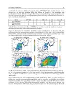
With such fretting corrosion conclusions
can frequently be made regarding the
position and size of the load zone,
fig. 14, and creeping of the rings.
Causes:
– Micromotion between fitted parts
where fits are too loose in relation to
the acting forces, but no creeping of
rings
– Form disturbance of fitting surfaces
– Shaft deflection, housing deformation
– Floating bearing function at ring with
circumferential load
Remedial measures:
– Provide floating bearing function at
ring with point load
– Use bearing seats which are as tight as
possible
– Make shaft (housing) more rigid to
bending
– Coat bearing seats
– Use dimensionally stable rings for high
operating temperatures (prevents fit
loosening due to ring expansion as a
result of changes in steel structure)
– Improve roundness of seats
– Check and improve, if required, the
surface quality of the seats
15 FAG
14: Fretting corrosion reveals the size of the load zone at the stationary outer ring
13: Fretting corrosion in bore of a cylindrical roller bearing inner ring with
seat too loose
3.2.2 Seizing marks or sliding wear
Symptoms:
Cold welding at the fitting surfaces
(inner ring bore, outer ring outside di -
ameter) and axial mating surfaces or also
shiny contact areas where surface rough -
ness is good, figs. 15, 16.
Wear of fitting surface and face, fig.
17, perhaps reduction in preload or
clearance enlargement.
Causes:
– Rotary motion between ring and
shaft/housing with loose fits under
circumferential load; with static load
and unbalance also
– Axial support of rings insufficient
– Sluggish movement of floating bear -
ing
Remedial measures:
– Use bearing seats which are as tight as
possible
– Extend axial mating surfaces
– Secure axial support
– Keep fitting surfaces dry
– Improve floating bearing function
FAG 16
Evaluation of running features and damage to dismounted bearings
Condition of seats
15: Seizing marks on the outside diameter as a result of outer ring creeping in the
housing
16: Seizing marks in the inner ring bore as a result of inner ring creeping on the shaft
17: Circumferential scoring and cold
welding at the inner ring faces as a
result of inner ring creeping on the
shaft
3.2.3 Uneven support of bearing
rings
Symptoms:
Seating marks not in the area of the
expected load zone.
Machining structure of fitting sur-
faces worn in some areas and completely
untouched in others, figs. 18, 19. Later
fatigue damage and fractures due to un-
even load distribution and bending of
rings. Lip fractures result from too little
support of tapered roller bearing cones,
fig. 20, and plastic setting phenomenon
from contact surfaces which are too
small.
Causes:
– Unsuitable design
– Inaccurate machining
Remedial measures:
– Change mating parts constructively
keeping uniform housing rigidity in
mind; if necessary use other bearings
– Check production of mating parts
17 FAG
Evaluation of running features and damage to dismounted bearings
Condition of seats
18: Outer ring outside diameter,
fretting corrosion at "tough points"
(e.g. ribs) in the housing
19: Outer ring outside diameter, only half its width supported
20: Lip fracture of a tapered roller bearing cone due to insufficient axial support
of face
Evaluation of running features and damage to dismounted bearings
Condition of seats
3.2.4 Lateral grazing tracks
Symptoms:
Circumferential scratch marks/wear
on the faces of the bearing rings or seals,
figs. 21, 22.
Causes:
– Insufficient fixation of the bearings in
the housing or on the shaft
– Large amount of external contamina-
tion with narrow gap between bearing
and mating part
– Loose mating parts
– Axial clearance too large
Remedial measures:
– Adjust parts correctly
– Ensure lubricant cleanliness
– Check axial clearance and make it
closer perhaps
FAG 18
21: Circumferential scoring and cold welding at the faces due to grazing by a
mating part
22: Seal damage due to lateral grazing
Evaluation of running features and damage to dismounted bearings
Pattern of rolling contact
3.3 Pattern of rolling contact
3.3.1 Source and significance of tracks
Regardless of the occurence of dam-
age, there are changes in the contact sur-
faces between rings and rolling elements
called tracks to be found on every bear-
ing which has been in operation. These
tracks arise from the roughening or
smoothening of the surface structure ori-
ginally produced. They are also charac-
terised by indentations made by cycled
foreign particles which are often micro-
scopically small. Conclusions can there-
fore be drawn from the tracks about the
quality of lubrication, lubricant clean-
liness and the direction of load as well as
its distribution in the bearing.
3.3.1.1 Normal tracks
Under rotary motion and load the
rolling elements leave tracks on the race-
ways which are bright in appearance
when the lubricant film separates well.
The individual pattern of the tracks is,
however, largely dependent on the
illumination of the surface but it should
be possible to recognise almost all the
machining structure particularly when
working with a magnifying glass and
microscope (compare with non-contact
areas at the edge of the raceway!). In-
dividual indentations of small foreign
particles are inevitable. When lubrica-
tion is particularly good they are the
only indication of the position of the
load zones in the bearing, fig 23.
When temperatures are above
approximately 80 °C discolouration of
the raceways or rolling elements is a fre-
quent feature. It originates from chemi-
cal reactions of the steel with the lubri-
cant or its additives and has no negative
effect on the service life of the bearing.
Quite the contrary: These surface
features frequently indicate effective
wear protection of an additive.
Usually brown or blue colours result.
However, no obvious conclusions can be
drawn from the colour about the operat-
ing temperature which led to its origin.
Very different shades of colour have at
times been observed on the rolling ele-
ments of a bearing although the operat-
ing conditions are very similar.
This oil discolouration should on no
account be confused with the tempering
colours which are found on faulty bear-
ings in rare cases and which arise as a re-
sult of much higher temperatures, see
section 3.3.5.
Tracks in the form of equatorial lines
are sometimes found on balls as well.
They appear on angular contact ball
bearings when the balls always have the
same rotary axis. Any significant reduc-
tion in life does not derive from them,
fig. 24.
19 FAG
23: Normal track, surface structure still
visible, just small indentations by
foreign particles
24: Ball with equatorial circumferential lines