Robot manipulators trends and development 2010 Part 15 ppsx
Bạn đang xem bản rút gọn của tài liệu. Xem và tải ngay bản đầy đủ của tài liệu tại đây (1.95 MB, 40 trang )
RobotManipulators,TrendsandDevelopment552
robot and program diverse tasks and later, if needed, the robot program can be translated
into another robot’s manufacturer language. This is also a useful feature that could be used
for learning how to program certain robot.
In the simulator, it is necessary to create tags and robot tasks associated to them. Tags are
those points for which the robot will carry out the welding operations. To complete the
programming process, the robot’s motion has to be adjusted with the help of the Teach
pendant and moving the compass to determine the robot movement. Alternatively, a
function inside the Teach Pendant called Jog, that manipulates the robot’s movement
through each one of the DOF, can be used (EES 2006).
4.1 Simulation Example
First of all, it is important to maintain intact the positions of the components within the
workcell at the beginning of each simulation, an initial state has to be selected and a robot
type. In our case we worked with the KUKA KR16 Industrial Robot. A snapshot of the
simulation is shown in figure 7(a) and in figure 7(b) the actual workcell is shown.
Fig. 7(a). Simulation welding process. Fig. 7(b). Real workcell
Despite the cell distribution and robot location and configuration, it is possible to make
contact and collision with other components. The simulator provides a Matrix of contacts
and clashes in order to reprogram the trajectories if necessary. Figure 8 shows the results of
the clashes with high relevance due to detected collisions between the torch and the work
table and also small contacts between robot articulations.
In Figure 8, it is also shown on the left hand side a graph of the area affected by the collision
between the robot and the torch with one product named “piece to be welded”. On the right
hand side, it shows the relation matrix of collisions and contacts, among all the devices. In
this example, the simulation resulted in a total of 19 interferences, from which 9 were
collisions and 10 contacts. In these results, the collisions are important since they can
damage some devices and even the robot.
All Types No filter on value All Statuses
Number of interferences: 19 (Clash:9, Contact:10, Clearance:0)
Interference, 3
Contact + Clash
Between all components
Results
All Types
No filter on value All Statuses
Number of interferences: 19 (Clash:9, Contact:10, Clearance:0)
Interference, 3
Contact + Clash
Between all components
Results
10166934 (10166904.1)
10166924pp (10166934pp.1)
Máquina de soldar (maqui)
Ensamble_final (ensamble)
Tanque3 (tanque3.1)
Area1 (Area-0022)
KR16:kr16.0 (kr16.0.1)
KR16:kr16.1 (kr16.1.1)
KR 1 6:k
r1 6 .6 ( kr 16. 6.1)
S ev en th_ ax is _to
p (s eve n )
KR 16
:k r1 6 .1 ( kr 16. 1.1 )
KR 16 :k r1 6 .0 (kr 16. 0.1 )
Ar ea 1 (A re a -C 02 2)
Ta nq ue 3 (tan qu e 3 . 1)
E ns am bl e_f in al (e ns am b
l e)
M aq ui na_ de_
sol da r (ma qu)
1 0
16 6 934 p p( )
KR 1 6:k r1 6 .5.6 (k r1 6.6 .5 .1)
KR 1 6:k r1 6 .4.6 (k
r1 6.6 .4 .1)
KR 16
:k r1 6 .3.6 (k r1 6.3 .6 .1)
KR 16 :k r1 6 .2.6 (k r1 6.6 .2 .1)
1 016 6 93 4 pp.1
1 016 6 934 (1 0166 934 .1)
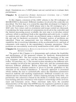
Fig. 8. Matrix simulation results
A human welder must be able to interpret all the results of this simulator. The examination
of the Standard CRAW-OT (Certified Robotic Arc Welding, Operator and Technician) by the
AWS is designed to test the knowledge of welding fundamentals and robotic welding (EES
2006). Table 1 presents the CRAW-OT subjects that can be evaluated in the simulator in
comparison with a real workcell.
Subject
Real
Workcell
Virtual
Simulator
Weld Equipment Setup
Welding Processes
Weld Examination
Definitions and Terminology
Symbols
Safety
Destructive Testing
Conversion and Calculation
Robot Programming
Welding Procedures
Programming Logic
Kinematics Concepts
Robot Arc Weld Cell Components
Table 1. Comparison between Real Workcell and Virtual Simulator
5. Robot Program Using Off-Line Programming
One of the most important tasks is programming the robot, which is considered very
difficult to evaluate because each brand has its own robot programming code. This
programming task is easier to evaluate since the simulator provides a conversion utility
ImplementationofanIntelligentRobotizedGMAWWeldingCell,Part1:DesignandSimulation 553
robot and program diverse tasks and later, if needed, the robot program can be translated
into another robot’s manufacturer language. This is also a useful feature that could be used
for learning how to program certain robot.
In the simulator, it is necessary to create tags and robot tasks associated to them. Tags are
those points for which the robot will carry out the welding operations. To complete the
programming process, the robot’s motion has to be adjusted with the help of the Teach
pendant and moving the compass to determine the robot movement. Alternatively, a
function inside the Teach Pendant called Jog, that manipulates the robot’s movement
through each one of the DOF, can be used (EES 2006).
4.1 Simulation Example
First of all, it is important to maintain intact the positions of the components within the
workcell at the beginning of each simulation, an initial state has to be selected and a robot
type. In our case we worked with the KUKA KR16 Industrial Robot. A snapshot of the
simulation is shown in figure 7(a) and in figure 7(b) the actual workcell is shown.
Fig. 7(a). Simulation welding process. Fig. 7(b). Real workcell
Despite the cell distribution and robot location and configuration, it is possible to make
contact and collision with other components. The simulator provides a Matrix of contacts
and clashes in order to reprogram the trajectories if necessary. Figure 8 shows the results of
the clashes with high relevance due to detected collisions between the torch and the work
table and also small contacts between robot articulations.
In Figure 8, it is also shown on the left hand side a graph of the area affected by the collision
between the robot and the torch with one product named “piece to be welded”. On the right
hand side, it shows the relation matrix of collisions and contacts, among all the devices. In
this example, the simulation resulted in a total of 19 interferences, from which 9 were
collisions and 10 contacts. In these results, the collisions are important since they can
damage some devices and even the robot.
All Types No filter on value All Statuses
Number of interferences: 19 (Clash:9, Contact:10, Clearance:0)
Interference, 3
Contact + Clash
Between all components
Results
All Types
No filter on value All Statuses
Number of interferences: 19 (Clash:9, Contact:10, Clearance:0)
Interference, 3
Contact + Clash
Between all components
Results
10166934 (10166904.1)
10166924pp (10166934pp.1)
Máquina de soldar (maqui)
Ensamble_final (ensamble)
Tanque3 (tanque3.1)
Area1 (Area-0022)
KR16:kr16.0 (kr16.0.1)
KR16:kr16.1 (kr16.1.1)
KR 1 6:k
r1 6 .6 ( kr 16. 6.1)
S ev en th_ ax is _to
p (s eve n )
KR 16
:k r1 6 .1 ( kr 16. 1.1 )
KR 16 :k r1 6 .0 (kr 16. 0.1 )
Ar ea 1 (A re a -C 02 2)
Ta nq ue 3 (tan qu e 3 . 1)
E ns am bl e_f in al (e ns am b
l e)
M aq ui na_ de_
sol da r (ma qu)
1 0
16 6 934 p p( )
KR 1 6:k r1 6 .5.6 (k r1 6.6 .5 .1)
KR 1 6:k r1 6 .4.6 (k
r1 6.6 .4 .1)
KR 16
:k r1 6 .3.6 (k r1 6.3 .6 .1)
KR 16 :k r1 6 .2.6 (k r1 6.6 .2 .1)
1 016 6 93 4 pp.1
1 016 6 934 (1 0166 934 .1)
All Types No filter on value All Statuses
Number of interferences: 19 (Clash:9, Contact:10, Clearance:0)
Interference, 3
Contact + Clash
Between all components
Results
All Types
No filter on value All Statuses
Number of interferences: 19 (Clash:9, Contact:10, Clearance:0)
Interference, 3
Contact + Clash
Between all components
Results
10166934 (10166904.1)
10166924pp (10166934pp.1)
Máquina de soldar (maqui)
Ensamble_final (ensamble)
Tanque3 (tanque3.1)
Area1 (Area-0022)
KR16:kr16.0 (kr16.0.1)
KR16:kr16.1 (kr16.1.1)
KR 1 6:k
r1 6 .6 ( kr 16. 6.1)
S ev en th_ ax is _to
p (s eve n )
KR 16
:k r1 6 .1 ( kr 16. 1.1 )
KR 16 :k r1 6 .0 (kr 16. 0.1 )
Ar ea 1 (A re a -C 02 2)
Ta nq ue 3 (tan qu e 3 . 1)
E ns am bl e_f in al (e ns am b
l e)
M aq ui na_ de_
sol da r (ma qu)
1 0
16 6 934 p p( )
KR 1 6:k r1 6 .5.6 (k r1 6.6 .5 .1)
KR 1 6:k r1 6 .4.6 (k
r1 6.6 .4 .1)
KR 16
:k r1 6 .3.6 (k r1 6.3 .6 .1)
KR 16 :k r1 6 .2.6 (k r1 6.6 .2 .1)
1 016 6 93 4 pp.1
1 016 6 934 (1 0166 934 .1)
Fig. 8. Matrix simulation results
A human welder must be able to interpret all the results of this simulator. The examination
of the Standard CRAW-OT (Certified Robotic Arc Welding, Operator and Technician) by the
AWS is designed to test the knowledge of welding fundamentals and robotic welding (EES
2006). Table 1 presents the CRAW-OT subjects that can be evaluated in the simulator in
comparison with a real workcell.
Subject
Real
Workcell
Virtual
Simulator
Weld Equipment Setup
Welding Processes
Weld Examination
Definitions and Terminology
Symbols
Safety
Destructive Testing
Conversion and Calculation
Robot Programming
Welding Procedures
Programming Logic
Kinematics Concepts
Robot Arc Weld Cell Components
Table 1. Comparison between Real Workcell and Virtual Simulator
5. Robot Program Using Off-Line Programming
One of the most important tasks is programming the robot, which is considered very
difficult to evaluate because each brand has its own robot programming code. This
programming task is easier to evaluate since the simulator provides a conversion utility
RobotManipulators,TrendsandDevelopment554
between different commercial robots. A code example produced by the simulator is
provided in Table 2.
Robot KUKA Robot FANUC Robot RAPID
&ACCESS RVP
&REL 1
&PARAM EDITMASK = *
DEF Welding_Task( )
;FOLD PTP ViaPoint2
Vel= 50 %
PDAT1 Tool[1]:cell2-
torch.1.
ToolFrame
Base[0];%{PE}
%R
4.1.5,%MKUKATPBASIS,
%CMOVE,%VPTP,%P 1:PTP,
2:ViaPoint2, 3:, 5:50,
7:PDAT1
$BWDSTART=FALSE
PDAT_ACT=PPDAT1
BAS(#PTP_DAT)
;ENDFOLD
END
/PROG Welding_Task
/ATTR
OWNER = MNEDITOR;
PROG_SIZE = 0;
FILE_NAME = ;
VERSION = 0;
LINE_COUNT = 0;
MEMORY_SIZE = 0;
PROTECT = READ_WRITE;
TCD: STACK_SIZE = 0,
TASK_PRIORITY = 50,
TIME_SLICE = 0,
BUSY_LAMP_OFF = 0,
ABORT_REQUEST = 0,
PAUSE_REQUEST = 0;
DEFAULT_GROUP = 1,1,1,*,*;
/POS
P[1]{
GP1: UF : 1, UT : 2, CONFIG:
'S 2 , 0, 0, 0',
X
= 1157.208 mm, Y =
2
12.886 mm, Z = 1002.855
mm,
W
= 136.239 deg, P =
11.951 deg, R = 103.725
deg };
%%%
VERSION:1
LANGUAGE:ENGLISH
%%%
MODULE Welding_Task_mod
PERS robtarget ViaPoint2:=
[[1157.208,212.886,1002.8551,
0,0,0
PERS robtarget
Tag1:=[[938.236,285.366,460.4
29],
[0.111893,0.51089,0.851944,0.
025754]
,[,0,0,0],[9E+09,9E+09,9E+09,
9E+09,9E+09,9E+09]];
PERS robtarget
PROC Welding_Task()
MoveJ
ViaPoint2,Default,Default,cel
l2-torch_1_ToolFrame;
MoveJ
Tag1,Default,Default,cell2-
torch_1_ToolFrame;
ENDPROC
ENDMODULE
Table 2. Program code for three different robots
The simulation process produces a robot program like the one shown in Table 2. This
program can be loaded to the specific robot controller to perform a real welding cycle using
the specified robot. This program is ready to start a welding task which can be programmed
either by using a predefined routine (off-line) or via a teaching device (on-line) (Lopez-
Juarez, I et al. 2009). In both cases a friendly user interface via voice has been designed in
order to facilitate robot programming which is described in section 7.
6. Robotized Welding System
The welding system used for experimentation is integrated by a KUKA KR16 industrial
robot. It also comprises a visual servo system with a ceiling mounted Basler A602fc CCD
camera as it is shown in figure 9.
Two computers are used, the Master Controller and the Speech Recognition. The Master
Controller is in charge of low-level serial communication with the robot controller using the
3964a protocol. It also connects to the Lincoln 455M power source and 10R wire feeder using
an I/O Data Acquisition Card so that the welding process can be switched on-off and the
current and voltage can be controlled by this computer. Additionally, it also handles the
programming user-interface through a wireless gamepad. On the other hand, the Speech
Recognition computer is in charge of giving voice commands to the robot in order to carry
out the welding tasks.
Fig. 9. Robotized Welding System
6.1 Distributed Robotic System
The concept of distributed systems and other technologies recently have made possible the
creation of new application called “Networked Robot Systems”. The main idea is to solve
the heterogeneity problem found in robotic systems due to the multiple component vendors
and computational platforms.
The development of robot systems based on distributed components is well supported by
different researchers. In (Amoretti et al., 2003), Michael Amoretti et al., present an analysis
of three techniques for sensor data distribution through the network. In (Amoretti, 2004) it is
proposed a robotic system using CORBA as communication architecture and it is
determined several new classes of telerobotic applications, such as virtual laboratories,
remote maintenance, etc. which leads to the distributed computation and the increase of
new developments like teleoperation of robots. In (Bottazzi et al., 2002), it is described a
software development of a distributed robotic system, using CORBA as middleware. The
system permits the development of Client-Server application with multi thread supporting
concurrent actions. The system is implemented in a laboratory using a manipulator robot
and two cameras, commanded by several users. In (Dalton et al., 2002), several middleware
are analyzed, CORBA, RMI (Remote Method Invocation) and MOM (Message Oriented
Middleware). But they created their own protocol based on MOM for controlling a robot
using Internet. In (Lopez-Juarez & Rios-Cabrera, 2006) a CORBA-based architecture for
robotic assembly using Artificial Neural Networks was introduced.
In the current investigation, though the system only includes two computers using the same
OS, the master controller and the speech recognition. It is important in this early stage to
ImplementationofanIntelligentRobotizedGMAWWeldingCell,Part1:DesignandSimulation 555
between different commercial robots. A code example produced by the simulator is
provided in Table 2.
Robot KUKA Robot FANUC Robot RAPID
&ACCESS RVP
&REL 1
&PARAM EDITMASK = *
DEF Welding_Task( )
;FOLD PTP ViaPoint2
Vel= 50 %
PDAT1 Tool[1]:cell2-
torch.1.
ToolFrame
Base[0];%{PE}
%R
4.1.5,%MKUKATPBASIS,
%CMOVE,%VPTP,%P 1:PTP,
2:ViaPoint2, 3:, 5:50,
7:PDAT1
$BWDSTART=FALSE
PDAT_ACT=PPDAT1
BAS(#PTP_DAT)
;ENDFOLD
END
/PROG Welding_Task
/ATTR
OWNER = MNEDITOR;
PROG_SIZE = 0;
FILE_NAME = ;
VERSION = 0;
LINE_COUNT = 0;
MEMORY_SIZE = 0;
PROTECT = READ_WRITE;
TCD: STACK_SIZE = 0,
TASK_PRIORITY = 50,
TIME_SLICE = 0,
BUSY_LAMP_OFF = 0,
ABORT_REQUEST = 0,
PAUSE_REQUEST = 0;
DEFAULT_GROUP = 1,1,1,*,*;
/POS
P[1]{
GP1: UF : 1, UT : 2, CONFIG:
'S 2 , 0, 0, 0',
X
= 1157.208 mm, Y =
2
12.886 mm, Z = 1002.855
mm,
W
= 136.239 deg, P =
11.951 deg, R = 103.725
deg };
%%%
VERSION:1
LANGUAGE:ENGLISH
%%%
MODULE Welding_Task_mod
PERS robtarget ViaPoint2:=
[[1157.208,212.886,1002.8551,
0,0,0
PERS robtarget
Tag1:=[[938.236,285.366,460.4
29],
[0.111893,0.51089,0.851944,0.
025754]
,[,0,0,0],[9E+09,9E+09,9E+09,
9E+09,9E+09,9E+09]];
PERS robtarget
PROC Welding_Task()
MoveJ
ViaPoint2,Default,Default,cel
l2-torch_1_ToolFrame;
MoveJ
Tag1,Default,Default,cell2-
torch_1_ToolFrame;
ENDPROC
ENDMODULE
Table 2. Program code for three different robots
The simulation process produces a robot program like the one shown in Table 2. This
program can be loaded to the specific robot controller to perform a real welding cycle using
the specified robot. This program is ready to start a welding task which can be programmed
either by using a predefined routine (off-line) or via a teaching device (on-line) (Lopez-
Juarez, I et al. 2009). In both cases a friendly user interface via voice has been designed in
order to facilitate robot programming which is described in section 7.
6. Robotized Welding System
The welding system used for experimentation is integrated by a KUKA KR16 industrial
robot. It also comprises a visual servo system with a ceiling mounted Basler A602fc CCD
camera as it is shown in figure 9.
Two computers are used, the Master Controller and the Speech Recognition. The Master
Controller is in charge of low-level serial communication with the robot controller using the
3964a protocol. It also connects to the Lincoln 455M power source and 10R wire feeder using
an I/O Data Acquisition Card so that the welding process can be switched on-off and the
current and voltage can be controlled by this computer. Additionally, it also handles the
programming user-interface through a wireless gamepad. On the other hand, the Speech
Recognition computer is in charge of giving voice commands to the robot in order to carry
out the welding tasks.
Fig. 9. Robotized Welding System
6.1 Distributed Robotic System
The concept of distributed systems and other technologies recently have made possible the
creation of new application called “Networked Robot Systems”. The main idea is to solve
the heterogeneity problem found in robotic systems due to the multiple component vendors
and computational platforms.
The development of robot systems based on distributed components is well supported by
different researchers. In (Amoretti et al., 2003), Michael Amoretti et al., present an analysis
of three techniques for sensor data distribution through the network. In (Amoretti, 2004) it is
proposed a robotic system using CORBA as communication architecture and it is
determined several new classes of telerobotic applications, such as virtual laboratories,
remote maintenance, etc. which leads to the distributed computation and the increase of
new developments like teleoperation of robots. In (Bottazzi et al., 2002), it is described a
software development of a distributed robotic system, using CORBA as middleware. The
system permits the development of Client-Server application with multi thread supporting
concurrent actions. The system is implemented in a laboratory using a manipulator robot
and two cameras, commanded by several users. In (Dalton et al., 2002), several middleware
are analyzed, CORBA, RMI (Remote Method Invocation) and MOM (Message Oriented
Middleware). But they created their own protocol based on MOM for controlling a robot
using Internet. In (Lopez-Juarez & Rios-Cabrera, 2006) a CORBA-based architecture for
robotic assembly using Artificial Neural Networks was introduced.
In the current investigation, though the system only includes two computers using the same
OS, the master controller and the speech recognition. It is important in this early stage to
RobotManipulators,TrendsandDevelopment556
consider the overall layout considering that additional components are being included in
the network.
6.1.1 CORBA specification and terminology
The CORBA specification (Henning, 2002), (OMG, 2000) is developed by the OMG (Object
Management Group), where it is specified a set of flexible abstractions and specific
necessary services to give a solution to a problem associated to a distributed environment.
The independence of CORBA for the programming language, the operating system and the
network protocols, makes it suitable for the development of new application and for its
integration into distributed systems already developed.
It is necessary to understand the CORBA terminology, which is listed below:
A CORBA object is a virtual entity, found by an ORB (Object Request Broker,
which is an ID string for each server) and it accepts petitions from the clients.
A destine object in the context of a CORBA petition, it is the CORBA object to
which the petition is made.
A client is an entity which makes a petition to a CORBA object.
A server is an application in which one or more CORBA objects run.
A petition is an operation invocation to a CORBA object, made by a client.
An object reference is a program used for identification, localization and
direction assignment of a CORBA object.
A server is an entity of the programming language that implements one or
more CORBA objects.
The petitions are showed in the figure 10: it is created by the client, goes through the ORB
and arrives to the server application.
Client Application
Client ORB Nucleus
DII
Static
Stub
ORB
Interface
Server Application
Server ORB Nucleus
Skeleton
Object
Adapter
ORB
Interface
DSI
Network
IDL De
p
endent
The same for any application
Several object adapters
Fig. 10. Common Object Request Broker Architecture (CORBA)
The client makes the petitions using static stub or using DII (Dynamic Invocation Interface).
In any case the client sends its petitions to the ORB nucleus linked with its processes. The
ORB of the client transmits its petitions to the ORB linked with a server application. The
ORB of the server redirect the petition to the object adapter just created, to the final object.
The object adapter directs its petition to the server which is implemented in the final object.
Both the client and the server can use static skeletons or the DSI (Dynamic Skeleton
Interface). The server sends the answer to the client application.
In order to make a petition and to get an answer, it is necessary to have the next CORBA
components:
Interface Definition Language (IDL): It defines the interfaces among the programs and is
independent of the programming language.
Language Mapping: it specifies how to translate the IDL to the different programming
languages.
Object Adapter: it is an object that makes transparent calling to other objects.
Protocol Inter-ORB: it is an architecture used for the interoperability among different ORBs.
The characteristics of the petitions invocation are: transparency in localization, transparency
of the server, language independence, implementation, architecture, operating system,
protocol and transport protocol. (Henning, 2002).
The aim of having a Master Controller, is to generate a high level central task controller
which uses its available senses (vision and voice commands) to make decisions, acquiring
the data on real-time and distributing the tasks for the welding task operation.
The architecture of the distributed system uses a Client/Server in each module. Figure 11
shows the relationship client-server in the Master Controller and Speech Recognition. With
the current configuration, it is possible a relationship from any other future server to any
client, since they share the same network. It is only necessary to know the name of the
server and obtain the IOR (Interoperable Object Reference). The interfaces or IDL
components would need to establish the relations among the modules.
Fig. 11. Client/server architecture of the distributed cell
7. Robot Controller Using Voice-Command Software
The system provides a user interface to receive directions in natural language using natural
language processing and Context Free Grammars (CFG). After the instruction is given, a
code is generated to execute ordered sentences to the welding system. To effectively
communicate the robot controller, it was needed to work in speech recognition (speech-to-text)
as well as in speech synthesis to acknowledge the command (text-to-speech). Using these
features it is possible to instruct the robot via voice-command and to receive an
ImplementationofanIntelligentRobotizedGMAWWeldingCell,Part1:DesignandSimulation 557
consider the overall layout considering that additional components are being included in
the network.
6.1.1 CORBA specification and terminology
The CORBA specification (Henning, 2002), (OMG, 2000) is developed by the OMG (Object
Management Group), where it is specified a set of flexible abstractions and specific
necessary services to give a solution to a problem associated to a distributed environment.
The independence of CORBA for the programming language, the operating system and the
network protocols, makes it suitable for the development of new application and for its
integration into distributed systems already developed.
It is necessary to understand the CORBA terminology, which is listed below:
A CORBA object is a virtual entity, found by an ORB (Object Request Broker,
which is an ID string for each server) and it accepts petitions from the clients.
A destine object in the context of a CORBA petition, it is the CORBA object to
which the petition is made.
A client is an entity which makes a petition to a CORBA object.
A server is an application in which one or more CORBA objects run.
A petition is an operation invocation to a CORBA object, made by a client.
An object reference is a program used for identification, localization and
direction assignment of a CORBA object.
A server is an entity of the programming language that implements one or
more CORBA objects.
The petitions are showed in the figure 10: it is created by the client, goes through the ORB
and arrives to the server application.
Client Application
Client ORB Nucleus
DII
Static
Stub
ORB
Interface
Server Application
Server ORB Nucleus
Skeleton
Object
Adapter
ORB
Interface
DSI
Network
IDL De
p
endent
The same for any application
Several object adapters
Fig. 10. Common Object Request Broker Architecture (CORBA)
The client makes the petitions using static stub or using DII (Dynamic Invocation Interface).
In any case the client sends its petitions to the ORB nucleus linked with its processes. The
ORB of the client transmits its petitions to the ORB linked with a server application. The
ORB of the server redirect the petition to the object adapter just created, to the final object.
The object adapter directs its petition to the server which is implemented in the final object.
Both the client and the server can use static skeletons or the DSI (Dynamic Skeleton
Interface). The server sends the answer to the client application.
In order to make a petition and to get an answer, it is necessary to have the next CORBA
components:
Interface Definition Language (IDL): It defines the interfaces among the programs and is
independent of the programming language.
Language Mapping: it specifies how to translate the IDL to the different programming
languages.
Object Adapter: it is an object that makes transparent calling to other objects.
Protocol Inter-ORB: it is an architecture used for the interoperability among different ORBs.
The characteristics of the petitions invocation are: transparency in localization, transparency
of the server, language independence, implementation, architecture, operating system,
protocol and transport protocol. (Henning, 2002).
The aim of having a Master Controller, is to generate a high level central task controller
which uses its available senses (vision and voice commands) to make decisions, acquiring
the data on real-time and distributing the tasks for the welding task operation.
The architecture of the distributed system uses a Client/Server in each module. Figure 11
shows the relationship client-server in the Master Controller and Speech Recognition. With
the current configuration, it is possible a relationship from any other future server to any
client, since they share the same network. It is only necessary to know the name of the
server and obtain the IOR (Interoperable Object Reference). The interfaces or IDL
components would need to establish the relations among the modules.
Fig. 11. Client/server architecture of the distributed cell
7. Robot Controller Using Voice-Command Software
The system provides a user interface to receive directions in natural language using natural
language processing and Context Free Grammars (CFG). After the instruction is given, a
code is generated to execute ordered sentences to the welding system. To effectively
communicate the robot controller, it was needed to work in speech recognition (speech-to-text)
as well as in speech synthesis to acknowledge the command (text-to-speech). Using these
features it is possible to instruct the robot via voice-command and to receive an
RobotManipulators,TrendsandDevelopment558
acknowledgement when tasks such as the weld perimeter, weld trajectory, stop, start, go-
home, etc. are accomplished.
The Voice Interface was based on Windows XP SP3 operating system using a Speech
Recognition PC (§ see section 6). The implementation of the voice command software for the
robotic welding system was developed in C++ using the Microsoft Software Development
Kit (SDK) and the Speech Application Programming Interface (SAPI) 5.0, which is a
programming standard that provides tools and components to speech recognition and
speech synthesis.
The SAPI is a high-level interface between the application and the speech engine that
implements low-level details to control and to manipulate the real-time operation in several
speech engines. There are two basic SAPI engines as it is shown in figure 12. One is the text-
to-speech system that synthesis strings and files into spoken audio signals using predefined
voices. On the other hand, the speech recognition engine or speech-to text converts the
human spoken voice into text strings and readable files. The SAPI is middleware that
provides an API and a device driver interface (DDI) for speech engines to implement. The
managed System.Speech namespace communicates to these engines both directly and
indirectly by calling through the SAPI.DLL. Native
Fig. 13. SAPI engines
There are several category interfaces apart from the speech engines that were used in the
application:
Audio
Used to control and customize real-time audio streams compatible with speech
synthesis.
Grammar Compiler
Used to dynamically define Context-Free Grammars (CFGs) and compile them into
the binary form used by the speech recognition engine.
Lexicon
Provides a uniform way for applications and engines to access the user lexicon,
application lexicon, and engine private lexicons. Lexicons provide custom word
pronunciations for speech synthesis.
7.1 Grammar
The Context Free Grammar (CFG) format in SAPI 5 defines the structure of grammars and
grammar rules using Extensible Markup Language (XML). The CFG/Grammar compiler
transforms the XML tags defining the grammar elements into a binary format used by SAPI
5-compliant SR engines. This compiling process can be performed either before or during
application run time.
The Speech SDK includes a grammar compiler, which can be used to author text grammars,
compile text grammars into the SAPI 5 binary format, and perform basic testing before
integration into an application. An example of the developed code is as follows:
<GRAMMAR LANGID="409">
<RULE NAME="RobotTask" ID="139" TOPLEVEL="ACTIVE">
<OPT>
<L>
<P>robot</P>
<P>stop</P>
<P>hello</P>
</L>
</OPT>
<OPT>
<L>
<P>weld</P>
<P>go</P>
<P>kuka</P>
</L>
</OPT>
<OPT>
<L>
<P>weld</P>
<P>objects</P>
<P>home</P>
</L>
</OPT>
</RULE>
</GRAMMAR>
<GRAMMAR LANGID="409">
</GRAMMAR>
In the program, <GRAMMAR> has a numeric attribute LANGID. We can observe at the
beginning of the program, there is also a RULE NAME where “RobotTask” is the
ImplementationofanIntelligentRobotizedGMAWWeldingCell,Part1:DesignandSimulation 559
acknowledgement when tasks such as the weld perimeter, weld trajectory, stop, start, go-
home, etc. are accomplished.
The Voice Interface was based on Windows XP SP3 operating system using a Speech
Recognition PC (§ see section 6). The implementation of the voice command software for the
robotic welding system was developed in C++ using the Microsoft Software Development
Kit (SDK) and the Speech Application Programming Interface (SAPI) 5.0, which is a
programming standard that provides tools and components to speech recognition and
speech synthesis.
The SAPI is a high-level interface between the application and the speech engine that
implements low-level details to control and to manipulate the real-time operation in several
speech engines. There are two basic SAPI engines as it is shown in figure 12. One is the text-
to-speech system that synthesis strings and files into spoken audio signals using predefined
voices. On the other hand, the speech recognition engine or speech-to text converts the
human spoken voice into text strings and readable files. The SAPI is middleware that
provides an API and a device driver interface (DDI) for speech engines to implement. The
managed System.Speech namespace communicates to these engines both directly and
indirectly by calling through the SAPI.DLL. Native
Fig. 13. SAPI engines
There are several category interfaces apart from the speech engines that were used in the
application:
Audio
Used to control and customize real-time audio streams compatible with speech
synthesis.
Grammar Compiler
Used to dynamically define Context-Free Grammars (CFGs) and compile them into
the binary form used by the speech recognition engine.
Lexicon
Provides a uniform way for applications and engines to access the user lexicon,
application lexicon, and engine private lexicons. Lexicons provide custom word
pronunciations for speech synthesis.
7.1 Grammar
The Context Free Grammar (CFG) format in SAPI 5 defines the structure of grammars and
grammar rules using Extensible Markup Language (XML). The CFG/Grammar compiler
transforms the XML tags defining the grammar elements into a binary format used by SAPI
5-compliant SR engines. This compiling process can be performed either before or during
application run time.
The Speech SDK includes a grammar compiler, which can be used to author text grammars,
compile text grammars into the SAPI 5 binary format, and perform basic testing before
integration into an application. An example of the developed code is as follows:
<GRAMMAR LANGID="409">
<RULE NAME="RobotTask" ID="139" TOPLEVEL="ACTIVE">
<OPT>
<L>
<P>robot</P>
<P>stop</P>
<P>hello</P>
</L>
</OPT>
<OPT>
<L>
<P>weld</P>
<P>go</P>
<P>kuka</P>
</L>
</OPT>
<OPT>
<L>
<P>weld</P>
<P>objects</P>
<P>home</P>
</L>
</OPT>
</RULE>
</GRAMMAR>
<GRAMMAR LANGID="409">
</GRAMMAR>
In the program, <GRAMMAR> has a numeric attribute LANGID. We can observe at the
beginning of the program, there is also a RULE NAME where “RobotTask” is the
RobotManipulators,TrendsandDevelopment560
grammatical rule; ID, the language identification and TOPLEVEL is declared ACTIVE, but it
can be dynamically configured in real-time. The user has to talk only TOPLEVEL rules for
the robot to recognise the words. For instance, in the program the words robot, stop,
hello, can be recognized by the engine. Note that these words are enclosed by <OPT> and
</OPT> directives.
Several words were included in the Lexicon being the more important: weld perimeter,
weld trajectory, stop, start, go-home.
8. Conclusions and Ongoing Work
In this chapter, we described the design and integration of a robotic welding cell using a 3D
simulation environment. The design was useful for building the CORBA-based distributed
robotized welding cell in this research project. Issues such as layout definition,
communication design, welding part design, robot and welding station commissioning were
considered. The design also included a voice-command driven environment using the
Microsoft Speech Application Interface V5.0. Definition of Context Free Grammars were
used so that it was possible to start a typical robot task using a human operator’s voice
using verbal commands such as “weld perimeter” or “weld trajectory”.
The design and simulation previous to the implementation of an automated welding cell is
useful, because possible errors can be prevented such as problems of area distribution,
security, dimensions, etc. In addition to its great utility to save costs and avoid unnecessary
damage to machinery and equipment.
The design of complex robot systems using multisensorial inputs, high-level machine
interfaces and distributed networked systems will be elements is of primary importance for
advance robot manipulators in the near future so that the work reported in this chapter
intents to demonstrate alternative guidelines to design such complex systems.
9. Acknowledgements
The authors wish to thank the following organizations who made possible this research: The
Consejo Nacional de Ciencia y Tecnologia (CONACyT) through Project Research Grant No.
61373, and for sponsoring Mr. Davila-Rios during his doctoral studies and to the
Corporacion Mexicana de Investigacion en Materiales for its support through Research
Grant Project No. GDH - IE - 2007.
10. References
Amoretti Michele; Stefano Bottazzi; Monica Reggiani & Stefano Caselli. (2003). "Evaluation
of Data Distribution Techniques in a CORBA-based Telerobotic System" Proceedings
of the 2003 IEEE/RSJ Intl. Conf. on Intelligent Robots and Systems (IROS 2003), October,
Las Vegas, NV.
Amoretti, Michele, Stefano Bottazzi, Stefano Caselli, Monica Reggiani, (2004), "Telerobotic
Systems Design based on Real-Time CORBA", Journal of Robotic Systems Volume 22,
Issue 4 , PP. 183 – 201.
Barney Dalton, Ken Taylor, (2000). “Distributed Robotics over the Internet”, IEEE Robotics
and Automation. 7(2): 22-27.
Bottazzi S., S. Caselli M. Reggiani & M. Amoretti, (2002). “A Software Framework based on
Real-Time CORBA for Telerobotic Systems”, Proceedings of the 2002 IEEE/RSJ Int.
Conference on Intelligent Robots and Systems, EPFL, Lausanne, Switzerland, October,
2002.
Holliday D. B., Gas-metal arc welding, (2005) ASM Handbook, Vol 6, Welding, Brazing and
Soldering, 2005 pp (180-185).
Henning, Michi, Steve Vinoski. (2002) "Programación Avanzada en CORBA con C++",
Addison Wesley, ISBN 84-7829-048-6.
I. Lopez-Juarez, R. Rios-Cabrera, & I. Davila-Rios (2009). Implementation of an Intelligent
Robotized GMAW Welding Cell, Part 2: Intuitive visual programming tool for
trajectory learning”. In Advances in Robot Manipulators, ISBN 978-953-7619-X-X.
Edited by IN-TECH, Vienna, Austria (In press).
Norrish, J. (1992) Advanced welding processes, Proceedings of the Institute of Physics
Publishing, 1992.
Hancock, R. & Johnsen, M. (2004) Development in guns and torches, Welding J 2004, 83(5),
pp29-32.
Lyttle, K A, Shielding gases, ASM Handbook, Vol 6, Welding, Brazing and Soldering, pp. 64-
69.
Anibal Ollero Baturone, (2001). Robotic, manipulators and Mobile robots. Alfaomega.
AWS: American Welding Society (2004). Certified Robotic Arc Welding Operator and
Technician. Approved American National Standard ANSI.
AWS: American Welding Society (2005). Specification for the Qualification of Robotic Arc
Welding Personnel. Approved American National Standard ANSI.
EES: Enterprise Engineering Solutions (2006). V5 Robotics Training Manual. Delmia
Education Services Enterprice.
Caie, Jim (2008). Discrete Manufacturers Driving Results with DELMIA V5 Automation
Platform. ARC Advisory Group.
Ericsson, Mikael, (2003). “Simulation of robotic TIG-welding“. PhD Thesis, Division of
Robotics Department of Mechanical Engineering Lund Institute of Technology Lund
University, P.O. Box 118, SE-221 00 Lund, Sweden.
Groover Mikell P., Weiss Mitchell, Nagel Roger & Odrey Nicholas. (1995). Industrial Robotics.
McGraw-Hill, Inc., USA pp. 375-376.
I. Lopez-Juarez, R Rios Cabrera. (2006) Distributed Architecture for Intelligent Robotic
Assembly, Part I: Design and Multimodal Learning. In Manufacturing the Future:
Concepts, Technologies & Visions. Edited by Vedran Kordic, Aleksandar Lazinica,
Munir Medran. Advanced Robotics Systems International. Pro Literatur Verlag,
Mammendorf, Germany. Pp. 337-366.
ImplementationofanIntelligentRobotizedGMAWWeldingCell,Part1:DesignandSimulation 561
grammatical rule; ID, the language identification and TOPLEVEL is declared ACTIVE, but it
can be dynamically configured in real-time. The user has to talk only TOPLEVEL rules for
the robot to recognise the words. For instance, in the program the words robot, stop,
hello, can be recognized by the engine. Note that these words are enclosed by <OPT> and
</OPT> directives.
Several words were included in the Lexicon being the more important: weld perimeter,
weld trajectory, stop, start, go-home.
8. Conclusions and Ongoing Work
In this chapter, we described the design and integration of a robotic welding cell using a 3D
simulation environment. The design was useful for building the CORBA-based distributed
robotized welding cell in this research project. Issues such as layout definition,
communication design, welding part design, robot and welding station commissioning were
considered. The design also included a voice-command driven environment using the
Microsoft Speech Application Interface V5.0. Definition of Context Free Grammars were
used so that it was possible to start a typical robot task using a human operator’s voice
using verbal commands such as “weld perimeter” or “weld trajectory”.
The design and simulation previous to the implementation of an automated welding cell is
useful, because possible errors can be prevented such as problems of area distribution,
security, dimensions, etc. In addition to its great utility to save costs and avoid unnecessary
damage to machinery and equipment.
The design of complex robot systems using multisensorial inputs, high-level machine
interfaces and distributed networked systems will be elements is of primary importance for
advance robot manipulators in the near future so that the work reported in this chapter
intents to demonstrate alternative guidelines to design such complex systems.
9. Acknowledgements
The authors wish to thank the following organizations who made possible this research: The
Consejo Nacional de Ciencia y Tecnologia (CONACyT) through Project Research Grant No.
61373, and for sponsoring Mr. Davila-Rios during his doctoral studies and to the
Corporacion Mexicana de Investigacion en Materiales for its support through Research
Grant Project No. GDH - IE - 2007.
10. References
Amoretti Michele; Stefano Bottazzi; Monica Reggiani & Stefano Caselli. (2003). "Evaluation
of Data Distribution Techniques in a CORBA-based Telerobotic System" Proceedings
of the 2003 IEEE/RSJ Intl. Conf. on Intelligent Robots and Systems (IROS 2003), October,
Las Vegas, NV.
Amoretti, Michele, Stefano Bottazzi, Stefano Caselli, Monica Reggiani, (2004), "Telerobotic
Systems Design based on Real-Time CORBA", Journal of Robotic Systems Volume 22,
Issue 4 , PP. 183 – 201.
Barney Dalton, Ken Taylor, (2000). “Distributed Robotics over the Internet”, IEEE Robotics
and Automation. 7(2): 22-27.
Bottazzi S., S. Caselli M. Reggiani & M. Amoretti, (2002). “A Software Framework based on
Real-Time CORBA for Telerobotic Systems”, Proceedings of the 2002 IEEE/RSJ Int.
Conference on Intelligent Robots and Systems, EPFL, Lausanne, Switzerland, October,
2002.
Holliday D. B., Gas-metal arc welding, (2005) ASM Handbook, Vol 6, Welding, Brazing and
Soldering, 2005 pp (180-185).
Henning, Michi, Steve Vinoski. (2002) "Programación Avanzada en CORBA con C++",
Addison Wesley, ISBN 84-7829-048-6.
I. Lopez-Juarez, R. Rios-Cabrera, & I. Davila-Rios (2009). Implementation of an Intelligent
Robotized GMAW Welding Cell, Part 2: Intuitive visual programming tool for
trajectory learning”. In Advances in Robot Manipulators, ISBN 978-953-7619-X-X.
Edited by IN-TECH, Vienna, Austria (In press).
Norrish, J. (1992) Advanced welding processes, Proceedings of the Institute of Physics
Publishing, 1992.
Hancock, R. & Johnsen, M. (2004) Development in guns and torches, Welding J 2004, 83(5),
pp29-32.
Lyttle, K A, Shielding gases, ASM Handbook, Vol 6, Welding, Brazing and Soldering, pp. 64-
69.
Anibal Ollero Baturone, (2001). Robotic, manipulators and Mobile robots. Alfaomega.
AWS: American Welding Society (2004). Certified Robotic Arc Welding Operator and
Technician. Approved American National Standard ANSI.
AWS: American Welding Society (2005). Specification for the Qualification of Robotic Arc
Welding Personnel. Approved American National Standard ANSI.
EES: Enterprise Engineering Solutions (2006). V5 Robotics Training Manual. Delmia
Education Services Enterprice.
Caie, Jim (2008). Discrete Manufacturers Driving Results with DELMIA V5 Automation
Platform. ARC Advisory Group.
Ericsson, Mikael, (2003). “Simulation of robotic TIG-welding“. PhD Thesis, Division of
Robotics Department of Mechanical Engineering Lund Institute of Technology Lund
University, P.O. Box 118, SE-221 00 Lund, Sweden.
Groover Mikell P., Weiss Mitchell, Nagel Roger & Odrey Nicholas. (1995). Industrial Robotics.
McGraw-Hill, Inc., USA pp. 375-376.
I. Lopez-Juarez, R Rios Cabrera. (2006) Distributed Architecture for Intelligent Robotic
Assembly, Part I: Design and Multimodal Learning. In Manufacturing the Future:
Concepts, Technologies & Visions. Edited by Vedran Kordic, Aleksandar Lazinica,
Munir Medran. Advanced Robotics Systems International. Pro Literatur Verlag,
Mammendorf, Germany. Pp. 337-366.
RobotManipulators,TrendsandDevelopment562
ImplementationofanIntelligentRobotizedGMAWWeldingCell,
Part2:Intuitivevisualprogrammingtoolfortrajectorylearning 563
ImplementationofanIntelligentRobotizedGMAWWeldingCell,Part2:
Intuitivevisualprogrammingtoolfortrajectorylearning
I.Lopez-Juarez,R.Rios-CabreraandI.Davila-Rios
x
Implementation of an Intelligent Robotized
GMAW Welding Cell, Part 2: Intuitive visual
programming tool for trajectory learning
I. Lopez-Juarez
1
, R. Rios-Cabrera
1
and I. Davila-Rios
2
1
Centro de Investigacion y de Estudios Avanzados del IPN
2
Corporacion Mexicana de Investigacion en Materiales SA de CV
Mexico
1. Introduction
Robotized GMAW welding is a demanding process. Current robots are able to perform
welding tasks continuously under different working conditions in low-scale production
such as shipbuilding or in high-scale production such as in the automotive industry. In well
defined and structured environments such as in the automotive industry robot
reprogramming is still necessary in order to cope with uncertainties. This additional task
involves hiring specialized personnel, lost of production time, quality assessment,
destructive testing, etc., which necessarily increases the production costs.
During the welding task, the joint part specification has to be met in order to meet the
desired quality and productivity in industry. However, there are several factors that affect
the process accuracy such as welding part positioning; motion errors in the production line,
mechanical errors, backlash, ageing of mechanisms, etc. which are error sources that make
robots to operate in uncertain conditions, i.e. unstructured environments. The scope of this
work is focused on the compensation of these stochastic errors generated during the process
and that the robot system needs to cope with in order to meet the required quality
specification. To reach this goal, it is required to have an appropriate test-bed integrated
with the process parameters sensing capacity (laser system, camera, proximity sensors, etc.)
to follow the welding bead and to provide robust information to the robot controller. The
use of multiple sensors and different computers make a centralised control very complex,
hence it is preferred the use of the CORBA specification to implement a Distributed System.
In this chapter we present the machine vision system and the distributed control for the
welding cell as well as the Human-Machine Interface (HMI) developed to “teach” the
manipulator any welding trajectory.
1
This work was carried out during Dr. Lopez-Juarez research visit at Corporacion Mexicana
de Investigacion en Materiales SA de CV (COMIMSA) under General and Specific
CINVESTAV-COMIMSA Collaboration Agreements.
26
RobotManipulators,TrendsandDevelopment564
The robust design solution as proposed in this research is a two-fold issue. First, it is
necessary to minimize design errors by simulating the whole welding process considering
issues like floor plant space, robot configuration, welding equipment and supplies, etc. and
second, the utilization of a novel teaching tool for welding trajectory. The contribution of
this research has been split in two parts: In part I, the robotic cell set up (including off-line
and on-line programming) using current 3D software simulation, voice command
simulation design, equipment commissioning and testing was presented; whereas in this
Part II, a novel robot programming tool for teaching welding trajectories and a built-in error
compensation during production of welded parts are presented.
The programmed tool for trajectory learning is implemented in a Visual C++ application
named StickWeld V1.0 that involves the use of a friendly Graphical User Interface (GUI) for
trajectory compensation and teaching. The software runs in a PC-based computer and uses a
top mounted fast Firewire Colour Camera, a wireless gamepad and a pointing stick. The
purpose of the software is to compensate on-line any error misalignment during perimeter
welding of flat metal parts. The system compensates any offset error in the robot’s welding
torch due to conveyor or line production transport errors. The misalignment is captured by
the camera and the image is processed in the server computer to find the new perimeter
information, which is translated into a new robot trajectory and sent to the robot controller
for execution. The teaching option can also be accessed via the GUI; by selecting this option
the teaching/learning mode is activated. While in this mode, the user can define any
welding trajectory using a stick as a pointer to define the trajectory. The trajectory input
data, parameters selection and the robot motion control is made through the wireless
gamepad controller so that the user has always full motion control on the robot assuring the
safety within the cell. Once the new trajectory is entered, the robot can repeat the operation
in another metal part. The system uses a three layer communication structure. The lowest
layer is the serial standard communication RS232, followed by the SIEMENS 3964r protocol
and at the top are the StickWeld commands that communicate the host PC master controller
with the KUKA KRC2 robot controller. The defined trajectory path is stored continuously in
a processing FIFO allocation in order to have a continuous interpolated motion at execution
time.
The organisation of the chapter is as follows. This introduction belongs to section 1, which
also includes the description of the distributed system and related work. In section 2, the
GMAW welding process and different subsystems of the workcell are explained. In section
3, issues concerning with the server-robot communication protocol are provided. In section
4, the program StickWeld V1.0, GUI and the use of the peripherals and programming modes
are described in detail. Finally, in section 5 conclusions are provided and the envisaged
future work is highlighted.
1.1 Distributed System and Related Work
The CORBA specification (Henning, 2002), is developed by the OMG (Object Management
Group), where it is specified a set of flexible abstractions and specific necessary services to
give a solution to a problem associated to a distributed environment. The independence of
CORBA for the programming language, the operating system and the network protocols,
makes it suitable for the development of new application and for its integration into
distributed systems already developed. In this investigation, it was decided to implement
CORBA due to previous experience in Robotic Assembly (Lopez-Juarez & Rios-Cabrera,
2006). For a comprehensive description of the specification as well as its integration in the
workcell, the reader is referred to (Davila-Rios, et al., 2009), where the distributed system is
described in detail.
Jia proposes robotized systems using CORBA as the communication architecture in
telerobotic applications like in virtual laboratories, remote maintenance, etc. (Jia, et al., 2002).
Other authors look more at new paradigms rather than interoperability at the object level,
but at the service level to facilitate the interoperability of industrial robots in the service
environment and what has been called: Service Oriented Architectures (SOA) (Veiga, et al.,
2007). Other authors use simple I/O devices like digitising pens to facilitate robot
programming (Pires, et al., 2007). In our case, we have taken ideas from the mentioned
authors and we have implemented a novel distributed programming tool to teach a robot
random welding trajectories.
2. Welding process and Robotic System
Gas Metal Arc Welding (GMAW) is a welding process which joins metals by heating the
metals to their melting point with an electric arc. The arc is between a continuous,
consumable electrode wire and the metal being welded. The arc is shielded from
contaminants in the atmosphere by a shielding gas.
GMAW can be done automatic by using an industrial robot manipulator as it is the case in
this research and without the constant adjusting of controls by a welder or operator.
Basic equipment for a typical GMAW automatic setup are:
Robot manipulator
Welding power source: provides welding power.
Wire feeders (constant speed and voltage-sensing): controls the supply of wire to
welding gun.
Constant speed feeder: used only with a constant voltage (CV) power source. This
type of feeder has a control cable that will connect to the power source. The control
cable supplies power to the feeder and allows the capability of remote voltage
control with certain power source/feeder combinations. The wire feed speed (WFS)
is set on the feeder and will always be constant for a given preset value.
Voltage-sensing feeder: can be used with either a constant voltage (CV) or constant
current (CC) - direct current (DC) power source. This type of feeder is powered by
the arc voltage and does not have a control cord. When set to (CV), the feeder is
similar to a constant speed feeder. When set to (CC), the wire feed speed depends
on the voltage present. The feeder changes the wire feed speed as the voltage
changes. A voltage sensing feeder does not have the capability of remote voltage
control.
Supply of electrode wire.
Welding gun: delivers electrode wire and shielding gas to the weld puddle.
Shielding gas cylinder: provides a supply of shielding gas to the arc.
When this process starts, the weld pool is shielded by an inert gas, giving the process the
popular designation of Metal Inert Gas (MIG). Nowadays actives gases such as carbon
dioxide or mixtures of inert and active gases are also used and the designation GMAW
includes all these cases. This process is widely used in industrial application due to its
numerous benefits. It can weld almost all metallic materials, in a large range of thicknesses
ImplementationofanIntelligentRobotizedGMAWWeldingCell,
Part2:Intuitivevisualprogrammingtoolfortrajectorylearning 565
The robust design solution as proposed in this research is a two-fold issue. First, it is
necessary to minimize design errors by simulating the whole welding process considering
issues like floor plant space, robot configuration, welding equipment and supplies, etc. and
second, the utilization of a novel teaching tool for welding trajectory. The contribution of
this research has been split in two parts: In part I, the robotic cell set up (including off-line
and on-line programming) using current 3D software simulation, voice command
simulation design, equipment commissioning and testing was presented; whereas in this
Part II, a novel robot programming tool for teaching welding trajectories and a built-in error
compensation during production of welded parts are presented.
The programmed tool for trajectory learning is implemented in a Visual C++ application
named StickWeld V1.0 that involves the use of a friendly Graphical User Interface (GUI) for
trajectory compensation and teaching. The software runs in a PC-based computer and uses a
top mounted fast Firewire Colour Camera, a wireless gamepad and a pointing stick. The
purpose of the software is to compensate on-line any error misalignment during perimeter
welding of flat metal parts. The system compensates any offset error in the robot’s welding
torch due to conveyor or line production transport errors. The misalignment is captured by
the camera and the image is processed in the server computer to find the new perimeter
information, which is translated into a new robot trajectory and sent to the robot controller
for execution. The teaching option can also be accessed via the GUI; by selecting this option
the teaching/learning mode is activated. While in this mode, the user can define any
welding trajectory using a stick as a pointer to define the trajectory. The trajectory input
data, parameters selection and the robot motion control is made through the wireless
gamepad controller so that the user has always full motion control on the robot assuring the
safety within the cell. Once the new trajectory is entered, the robot can repeat the operation
in another metal part. The system uses a three layer communication structure. The lowest
layer is the serial standard communication RS232, followed by the SIEMENS 3964r protocol
and at the top are the StickWeld commands that communicate the host PC master controller
with the KUKA KRC2 robot controller. The defined trajectory path is stored continuously in
a processing FIFO allocation in order to have a continuous interpolated motion at execution
time.
The organisation of the chapter is as follows. This introduction belongs to section 1, which
also includes the description of the distributed system and related work. In section 2, the
GMAW welding process and different subsystems of the workcell are explained. In section
3, issues concerning with the server-robot communication protocol are provided. In section
4, the program StickWeld V1.0, GUI and the use of the peripherals and programming modes
are described in detail. Finally, in section 5 conclusions are provided and the envisaged
future work is highlighted.
1.1 Distributed System and Related Work
The CORBA specification (Henning, 2002), is developed by the OMG (Object Management
Group), where it is specified a set of flexible abstractions and specific necessary services to
give a solution to a problem associated to a distributed environment. The independence of
CORBA for the programming language, the operating system and the network protocols,
makes it suitable for the development of new application and for its integration into
distributed systems already developed. In this investigation, it was decided to implement
CORBA due to previous experience in Robotic Assembly (Lopez-Juarez & Rios-Cabrera,
2006). For a comprehensive description of the specification as well as its integration in the
workcell, the reader is referred to (Davila-Rios, et al., 2009), where the distributed system is
described in detail.
Jia proposes robotized systems using CORBA as the communication architecture in
telerobotic applications like in virtual laboratories, remote maintenance, etc. (Jia, et al., 2002).
Other authors look more at new paradigms rather than interoperability at the object level,
but at the service level to facilitate the interoperability of industrial robots in the service
environment and what has been called: Service Oriented Architectures (SOA) (Veiga, et al.,
2007). Other authors use simple I/O devices like digitising pens to facilitate robot
programming (Pires, et al., 2007). In our case, we have taken ideas from the mentioned
authors and we have implemented a novel distributed programming tool to teach a robot
random welding trajectories.
2. Welding process and Robotic System
Gas Metal Arc Welding (GMAW) is a welding process which joins metals by heating the
metals to their melting point with an electric arc. The arc is between a continuous,
consumable electrode wire and the metal being welded. The arc is shielded from
contaminants in the atmosphere by a shielding gas.
GMAW can be done automatic by using an industrial robot manipulator as it is the case in
this research and without the constant adjusting of controls by a welder or operator.
Basic equipment for a typical GMAW automatic setup are:
Robot manipulator
Welding power source: provides welding power.
Wire feeders (constant speed and voltage-sensing): controls the supply of wire to
welding gun.
Constant speed feeder: used only with a constant voltage (CV) power source. This
type of feeder has a control cable that will connect to the power source. The control
cable supplies power to the feeder and allows the capability of remote voltage
control with certain power source/feeder combinations. The wire feed speed (WFS)
is set on the feeder and will always be constant for a given preset value.
Voltage-sensing feeder: can be used with either a constant voltage (CV) or constant
current (CC) - direct current (DC) power source. This type of feeder is powered by
the arc voltage and does not have a control cord. When set to (CV), the feeder is
similar to a constant speed feeder. When set to (CC), the wire feed speed depends
on the voltage present. The feeder changes the wire feed speed as the voltage
changes. A voltage sensing feeder does not have the capability of remote voltage
control.
Supply of electrode wire.
Welding gun: delivers electrode wire and shielding gas to the weld puddle.
Shielding gas cylinder: provides a supply of shielding gas to the arc.
When this process starts, the weld pool is shielded by an inert gas, giving the process the
popular designation of Metal Inert Gas (MIG). Nowadays actives gases such as carbon
dioxide or mixtures of inert and active gases are also used and the designation GMAW
includes all these cases. This process is widely used in industrial application due to its
numerous benefits. It can weld almost all metallic materials, in a large range of thicknesses
RobotManipulators,TrendsandDevelopment566
(above 1 mm up to 30 mm or more) and is effective in all positions. GMAW is a very
economic process because it has higher deposition rates than for example the manual metal
arc process, and does not require frequent stops to change electrodes, as is the case of this
former process. Less operator skill is required than for other conventional processes because
electrode wire is fed automatically (semi-automatic process) and a self-adjustment
mechanism maintains the arc length approximately constant even when the distance weld
torch to work-piece varies within certain limits. These advantage make the process very well
adapted to be automated and particularly to robotic welding applications. The process is
sensitive to the effects of wind, which can disperse the shielding gas, and it is difficult to use
in narrow spaces due to the torch size (Holliday, D B 2005).
2.1. Robotized Welding System
The welding system used for experimentation is integrated by a KUKA KR16 industrial
robot. It also comprises a visual servo system with a ceiling mounted Basler A602fc CCD
camera as it is shown in figure 1.
Fig. 1. Robotized Welding System
Two computers are used, the Master Controller and the Speech Recognition computer. The
Master Controller is a PC Intel Xeon a 1.86GHz with 3GB RAM in charge of low-level serial
communication with the robot controller using the 3964a protocol. It also connects to the
Lincoln 455M power source and 10R wire feeder using an I/O Data Acquisition Card so that
the welding process can be switched on-off and the current and voltage can be controlled by
this computer. Additionally, it also handles the programming user-interface through a
wireless gamepad. On the other hand, the Speech Recognition computer is in charge of
giving voice commands to the robot in order to carry out the welding tasks.
The cell is based on the CORBA omniORB 4.1 Open Source GNU. The distributed system is
designed to work within a wireless network. The elements of the wireless distributed
system are described in the following sections.
2.1.1 Master Controller
The master controller connects to four subsystems as it could be seen in figure 1, namely:
KUKA KRC2 Robot Controller
GMAW Power source and wire feeder
Vision System
Programming Tool for Trajectory Learning
Each of these subsystems is explained below.
KUKA KRC2 Robot Controller
The KUKA KR16 robot is used in slave mode. Its motion is directed in low-level using the
3964a protocol and the RS232 serial communication. During operations a slave motion
program in KPL runs in the KRC2 controller. This motion program is in charge, among
other options, of the arm incremental motions, selection of tool/world coordinates, motion
distance and speed. The other communication program resides in the Master Controller and
forms part of the Stick Weld application.
GMAW Power source and wire feeder
The control and communication between the master controller and the power source and
wire feeder is established using a general purpose DAC Sensoray 626. This is illustrated in
figure 2. This card connects to the power feed to switch ON/OFF the power. It is also
possible to modify the voltage and current. This was achieved by replacing the encoders
from the voltage and current controls of the 455M Power Feed and to emulate its operation
using a PIC microcontroller. The microcontroller receives a voltage or current data from the
welding application and it translates in Gray code and send its data to the power feed,
which in turn controls the wire feeder to the welding gun.
Fig. 2. Welding System
ImplementationofanIntelligentRobotizedGMAWWeldingCell,
Part2:Intuitivevisualprogrammingtoolfortrajectorylearning 567
(above 1 mm up to 30 mm or more) and is effective in all positions. GMAW is a very
economic process because it has higher deposition rates than for example the manual metal
arc process, and does not require frequent stops to change electrodes, as is the case of this
former process. Less operator skill is required than for other conventional processes because
electrode wire is fed automatically (semi-automatic process) and a self-adjustment
mechanism maintains the arc length approximately constant even when the distance weld
torch to work-piece varies within certain limits. These advantage make the process very well
adapted to be automated and particularly to robotic welding applications. The process is
sensitive to the effects of wind, which can disperse the shielding gas, and it is difficult to use
in narrow spaces due to the torch size (Holliday, D B 2005).
2.1. Robotized Welding System
The welding system used for experimentation is integrated by a KUKA KR16 industrial
robot. It also comprises a visual servo system with a ceiling mounted Basler A602fc CCD
camera as it is shown in figure 1.
Fig. 1. Robotized Welding System
Two computers are used, the Master Controller and the Speech Recognition computer. The
Master Controller is a PC Intel Xeon a 1.86GHz with 3GB RAM in charge of low-level serial
communication with the robot controller using the 3964a protocol. It also connects to the
Lincoln 455M power source and 10R wire feeder using an I/O Data Acquisition Card so that
the welding process can be switched on-off and the current and voltage can be controlled by
this computer. Additionally, it also handles the programming user-interface through a
wireless gamepad. On the other hand, the Speech Recognition computer is in charge of
giving voice commands to the robot in order to carry out the welding tasks.
The cell is based on the CORBA omniORB 4.1 Open Source GNU. The distributed system is
designed to work within a wireless network. The elements of the wireless distributed
system are described in the following sections.
2.1.1 Master Controller
The master controller connects to four subsystems as it could be seen in figure 1, namely:
KUKA KRC2 Robot Controller
GMAW Power source and wire feeder
Vision System
Programming Tool for Trajectory Learning
Each of these subsystems is explained below.
KUKA KRC2 Robot Controller
The KUKA KR16 robot is used in slave mode. Its motion is directed in low-level using the
3964a protocol and the RS232 serial communication. During operations a slave motion
program in KPL runs in the KRC2 controller. This motion program is in charge, among
other options, of the arm incremental motions, selection of tool/world coordinates, motion
distance and speed. The other communication program resides in the Master Controller and
forms part of the Stick Weld application.
GMAW Power source and wire feeder
The control and communication between the master controller and the power source and
wire feeder is established using a general purpose DAC Sensoray 626. This is illustrated in
figure 2. This card connects to the power feed to switch ON/OFF the power. It is also
possible to modify the voltage and current. This was achieved by replacing the encoders
from the voltage and current controls of the 455M Power Feed and to emulate its operation
using a PIC microcontroller. The microcontroller receives a voltage or current data from the
welding application and it translates in Gray code and send its data to the power feed,
which in turn controls the wire feeder to the welding gun.
Fig. 2. Welding System
RobotManipulators,TrendsandDevelopment568
Vision System
The vision system was implemented using a fast Firewire Camera Basler A602fc with a 1/2”
CCD sensor with 656 x 490 pixel resolution and using a IEEE 1394 bus. The application
program for the vision system was developed in C++ using Visual Studio 2005 and using
the SDK from Basler. This application is embedded into the Master Controller.
During welding tasks, the vision system is used to recognise welding trajectories. The
distributed system defines several methods to be used that are available for other
clients/server elements. The IDL functions that are available from other elements are (See
(Davila-Rios, et al. 2009) for further details):
Functions for robot motion
Robot status
Workcell status
Force/Torque sensing
Available welding trajectories for clients
Modification functions for the welding power source
Welding machine status
General parameters
Others.
The camera system is used to input data to program the robot new trajectories and to correct
any misalignment during part welding but also it is being used as an input to the object
recognition application. This object recognition is a developed application for 2.5D object
recognition, complete details of the algorithm and development is explained further in this
book (Lopez-Juarez, et al., 2009).
The server share methods for other object recognition through the following IDL methods:
Object recognition
Data from the recognised object
Robot training execution
Data from the training task
Others
Programming Tool for Trajectory Learning
The master controller computer also uses the vision system, a wireless gamepad and a
teaching tool (pointing stick) to train the robot new welding trajectories. In terms of the IDL
functions there are some elements that are used for teaching purposes.
Industrial Robot KUKA KR16
The robot only works as a service provider. The master controller has access to its general
parameters such as speed; world/tool coordinates selection, motion axis, etc. The
communication is serial and there are no IDL functions, since it is not a CORBA client or
server, but it is used by a server (the master controller).
Speech recognition
This system is based on the Microsoft SAPI 5.0 and works with Context Free Grammar. It
generally works as a client making requests to the other systems. The IDL functions mostly
interact with the robot using the following services:
Speech recognition initialisation
Stop the robot
General parameters
The speech recognition system can be used directly to control the workcell or to initialise a
specific process within the cell. The reader is referred to (Davila-Rios, et al., 2009) for further
details on the implementation of the speech recognition system.
Additionally, the robot controller also can use another system for part location purposes.
The workcell includes a Hytrol TA model belt conveyor, which is speed/position controlled
by a Micromaster 420. The belt conveyor IDL functions are:
Belt motion with X speed
Status from the current location
General parameters configuration
The belt conveyor only accepts directions and provides current status. This is considered a
server only since it never acts as a client.
The issues concerning with the server-robot communication protocol are described in detail
in section 3. In section 4, the program StickWeld V1.0, GUI and the use of the peripherals
and programming modes are explained.
3. Programming and communication
The welding software is connected through CORBA to the other servers (the other modules
of the manufacturing cell) as it was showed in figure 1. But a complete real-time
communication is hold as well with the robot controller in order to access the robot
movements.
In order to obtain continuous robot movements it was necessary to implement a stack of
communication protocols. As it can be seen in figure 3, the welding SERVER (Master
Controller) holds both, a CORBA module, and a set of functions to control the robot. The
CORBA module embedded in the Stick Weld system gives access to other modules of the
cell to manipulate some robotic tailored functions. This allows for example to receive direct
commands from the speech module and to execute them.
Fig. 3. Stack of communication protocols Master Controller PC - KUKA KR16
In the lowest layer, the RS232 standard is used for communication protocol. The second
layer uses the SIEMENS 3964R protocol. The third layer contains the basic commands
definition to be executed in the robot.
ImplementationofanIntelligentRobotizedGMAWWeldingCell,
Part2:Intuitivevisualprogrammingtoolfortrajectorylearning 569
Vision System
The vision system was implemented using a fast Firewire Camera Basler A602fc with a 1/2”
CCD sensor with 656 x 490 pixel resolution and using a IEEE 1394 bus. The application
program for the vision system was developed in C++ using Visual Studio 2005 and using
the SDK from Basler. This application is embedded into the Master Controller.
During welding tasks, the vision system is used to recognise welding trajectories. The
distributed system defines several methods to be used that are available for other
clients/server elements. The IDL functions that are available from other elements are (See
(Davila-Rios, et al. 2009) for further details):
Functions for robot motion
Robot status
Workcell status
Force/Torque sensing
Available welding trajectories for clients
Modification functions for the welding power source
Welding machine status
General parameters
Others.
The camera system is used to input data to program the robot new trajectories and to correct
any misalignment during part welding but also it is being used as an input to the object
recognition application. This object recognition is a developed application for 2.5D object
recognition, complete details of the algorithm and development is explained further in this
book (Lopez-Juarez, et al., 2009).
The server share methods for other object recognition through the following IDL methods:
Object recognition
Data from the recognised object
Robot training execution
Data from the training task
Others
Programming Tool for Trajectory Learning
The master controller computer also uses the vision system, a wireless gamepad and a
teaching tool (pointing stick) to train the robot new welding trajectories. In terms of the IDL
functions there are some elements that are used for teaching purposes.
Industrial Robot KUKA KR16
The robot only works as a service provider. The master controller has access to its general
parameters such as speed; world/tool coordinates selection, motion axis, etc. The
communication is serial and there are no IDL functions, since it is not a CORBA client or
server, but it is used by a server (the master controller).
Speech recognition
This system is based on the Microsoft SAPI 5.0 and works with Context Free Grammar. It
generally works as a client making requests to the other systems. The IDL functions mostly
interact with the robot using the following services:
Speech recognition initialisation
Stop the robot
General parameters
The speech recognition system can be used directly to control the workcell or to initialise a
specific process within the cell. The reader is referred to (Davila-Rios, et al., 2009) for further
details on the implementation of the speech recognition system.
Additionally, the robot controller also can use another system for part location purposes.
The workcell includes a Hytrol TA model belt conveyor, which is speed/position controlled
by a Micromaster 420. The belt conveyor IDL functions are:
Belt motion with X speed
Status from the current location
General parameters configuration
The belt conveyor only accepts directions and provides current status. This is considered a
server only since it never acts as a client.
The issues concerning with the server-robot communication protocol are described in detail
in section 3. In section 4, the program StickWeld V1.0, GUI and the use of the peripherals
and programming modes are explained.
3. Programming and communication
The welding software is connected through CORBA to the other servers (the other modules
of the manufacturing cell) as it was showed in figure 1. But a complete real-time
communication is hold as well with the robot controller in order to access the robot
movements.
In order to obtain continuous robot movements it was necessary to implement a stack of
communication protocols. As it can be seen in figure 3, the welding SERVER (Master
Controller) holds both, a CORBA module, and a set of functions to control the robot. The
CORBA module embedded in the Stick Weld system gives access to other modules of the
cell to manipulate some robotic tailored functions. This allows for example to receive direct
commands from the speech module and to execute them.
Fig. 3. Stack of communication protocols Master Controller PC - KUKA KR16
In the lowest layer, the RS232 standard is used for communication protocol. The second
layer uses the SIEMENS 3964R protocol. The third layer contains the basic commands
definition to be executed in the robot.
RobotManipulators,TrendsandDevelopment570
Some of these commands are presented in table 1.
Functions
GoHome
CoordWorld
RestartFIFO
AddMovement(x,y,z,speed)
StartFIFOprocessing
StopFIFOprocessing
Fromcurrent+1deleteallFIFO
EmergencyStop
DefineApproximation
SimpleMovement(x,y,z,speed)
SimpleRotation(x,y,z,speed)
Exitprogram
Table 1. Basic functions available in the communication.
In order to create a continuous movement of the robot, interpolation is carried out using a
FIFO structure in the robot controller programming. This structure maintains the
movements until a buffer is empty, or until a stop command is received. This could be an
emergency stop for example or other stop function. The internal programming uses
different interruptions to achieve continuous movements while receiving other commands
at the same time, and to generate soft movements of discrete coordinates.
4. Stick Weld 1.0
Stick Weld 1.0 is a beta software project, presented as a prototype to create a functional
powerful tool to teach easily different trajectories to an industrial robot. A user interface was
developed containing two main functions:
1. It allows the robot to follow the contour of irregular or regular metal objects to be
welded.
2. It allows a real-time robot programming tool to follow and weld random paths on
flat surfaces.
To execute these tasks, an industrial robot is used, as well as different basic programming
elements to teach the robot the desired trajectories. It includes basically: Fast colour camera,
pointing stick, a gamepad, and a welding table. These elements are showed in figure 4.
In order to keep the programming tools simple, the robot is taught using an interface
consisting of a pointing stick and a wireless gamepad. With the pointing stick, the user only
has to move the stick on the metal part using the desired trajectory. The camera captures the
2D trajectories that the robot must follow later, executing the welding task. When the
teaching is being done, the vision system tracks the movements and records the Cartesian
coordinates of the pointing stick as illustrated in figure 5.
Fig. 4. Basic elements for trajectory programming
Fig. 5. Tracking of the pointing stick
All main functions are included in the buttons of the gamepad, to provide a complete useful
interface. Among these functions, the start-finish robot movements are included as well as
an emergency stop. Once the programming is finished, it is intended that the vision system,
must recognize a specific piece, and also recall the already programmed objects (including
all trajectories and configurations) and apply that in the task execution.
While scanning the object to be welded, all the contour, holes and special forms founded in
the piece are recorded and converted to coordinates that the robot could follow if necessary.
An example is provided in figure 6 where two embedded contours were identifies and
recorded. In the upper part of the piece desired trajectories are computed. The vision system
also has the option to work with different background colours. As showed in figure 6, the
system works with a white metal surface and in this case a white pointing stick with a black
tip was employed.
ImplementationofanIntelligentRobotizedGMAWWeldingCell,
Part2:Intuitivevisualprogrammingtoolfortrajectorylearning 571
Some of these commands are presented in table 1.
Functions
GoHome
CoordWorld
RestartFIFO
AddMovement(x,y,z,speed)
StartFIFOprocessing
StopFIFOprocessing
Fromcurrent+1deleteallFIFO
EmergencyStop
DefineApproximation
SimpleMovement(x,y,z,speed)
SimpleRotation(x,y,z,speed)
Exitprogram
Table 1. Basic functions available in the communication.
In order to create a continuous movement of the robot, interpolation is carried out using a
FIFO structure in the robot controller programming. This structure maintains the
movements until a buffer is empty, or until a stop command is received. This could be an
emergency stop for example or other stop function. The internal programming uses
different interruptions to achieve continuous movements while receiving other commands
at the same time, and to generate soft movements of discrete coordinates.
4. Stick Weld 1.0
Stick Weld 1.0 is a beta software project, presented as a prototype to create a functional
powerful tool to teach easily different trajectories to an industrial robot. A user interface was
developed containing two main functions:
1. It allows the robot to follow the contour of irregular or regular metal objects to be
welded.
2. It allows a real-time robot programming tool to follow and weld random paths on
flat surfaces.
To execute these tasks, an industrial robot is used, as well as different basic programming
elements to teach the robot the desired trajectories. It includes basically: Fast colour camera,
pointing stick, a gamepad, and a welding table. These elements are showed in figure 4.
In order to keep the programming tools simple, the robot is taught using an interface
consisting of a pointing stick and a wireless gamepad. With the pointing stick, the user only
has to move the stick on the metal part using the desired trajectory. The camera captures the
2D trajectories that the robot must follow later, executing the welding task. When the
teaching is being done, the vision system tracks the movements and records the Cartesian
coordinates of the pointing stick as illustrated in figure 5.
Fig. 4. Basic elements for trajectory programming
Fig. 5. Tracking of the pointing stick
All main functions are included in the buttons of the gamepad, to provide a complete useful
interface. Among these functions, the start-finish robot movements are included as well as
an emergency stop. Once the programming is finished, it is intended that the vision system,
must recognize a specific piece, and also recall the already programmed objects (including
all trajectories and configurations) and apply that in the task execution.
While scanning the object to be welded, all the contour, holes and special forms founded in
the piece are recorded and converted to coordinates that the robot could follow if necessary.
An example is provided in figure 6 where two embedded contours were identifies and
recorded. In the upper part of the piece desired trajectories are computed. The vision system
also has the option to work with different background colours. As showed in figure 6, the
system works with a white metal surface and in this case a white pointing stick with a black
tip was employed.
RobotManipulators,TrendsandDevelopment572
Fig. 6. Automatic detection of contours
Figure 7 shows a main screen of the software showing the designed GUI. There is a direct
access to different configurations of the visual programming. The button: Mover Robot,
execute different manual movements such as Go Home Position, Rotation in Z direction, etc.
Fig. 7. Main Program Interface
It has two inputs, Distancia given in millimetres and Velocidad (Speed), which is given in
m/s. The interface has also two buttons for automatic processing of the already recorded
trajectories. The first one is Iniciar Perimetro (Start Perimeter), which starts the
communication with the robot to follow the trajectory of a workpiece perimeter for welding
purposes. The second button Proceso Interno (Internal Process), gives the instructions to the
robot of welding all internal pre-recorded trajectories in the current object. Those options
can be triggered also from the wireless gamepad.
The general configuration includes, diameter of pointing stick, threshold values, and
scanning speed for the movements of the stick. For the programming of trajectories, some
geometrical predefined figures have been programmed, such as closed areas, open lines,
and zones. Also a visual configuration is available to help introducing new trajectories of a
specific type (i.e. closed area, line). These are identified in the upper toolbar as Ar, Li and
Zo.
There are other features that can be accessed via the menu bar or the upper left toolbar. They
are intended to modify the camera settings such as brightness and shutter speed and other
options such as taking a single snapshot or taking image data continuously.
5. Conclusions and further work
During welding tasks there are quality specifications to be met. However, there are several
factors that affect the process accuracy such as welding part positioning; motion errors in
the production line, mechanical errors, backlash, ageing of mechanisms, etc. which are
error sources that make robots to operate in uncertain conditions, i.e. unstructured
environments. The scope of this work has been focused on the compensation of these
errors generated during the welding process and that the robot system needs to
compensate automatically.
The proposed solution includes the development of the StickWeld V1.0 application which
is a windows based solution programmed in Visual C++ that uses a CCD camera, Basler
SDK, wireless gamepad and pointing stick as a teaching tools. The system also uses IDL
functions so that the manipulator can receive verbal instructions such as motion
commands or start/stop the task.
The developed user interface contains two main functions. One operation is to follow the
contour of irregular or regular metal objects to be welded and the other is to follow and
weld random paths on flat surfaces.
Simple welding trajectories were tested using the KUKA manipulator as shown in figure
8. Several issues rose from the accomplished welding tasks such as starting point
synchronization, best torch angle, setting of the correct parameters (voltage and wire
speed). It was detected that the geometric parameters such as width and high of the seam
weld were not uniform along the paths, though the trajectory was correctly followed.
Fig. 8. Robot welding
On going work is looking at improving the actual welding stage by improving the selection
of the welding parameters namely, voltage, current and wire feeding speed. At present, the
ImplementationofanIntelligentRobotizedGMAWWeldingCell,
Part2:Intuitivevisualprogrammingtoolfortrajectorylearning 573
Fig. 6. Automatic detection of contours
Figure 7 shows a main screen of the software showing the designed GUI. There is a direct
access to different configurations of the visual programming. The button: Mover Robot,
execute different manual movements such as Go Home Position, Rotation in Z direction, etc.
Fig. 7. Main Program Interface
It has two inputs, Distancia given in millimetres and Velocidad (Speed), which is given in
m/s. The interface has also two buttons for automatic processing of the already recorded
trajectories. The first one is Iniciar Perimetro (Start Perimeter), which starts the
communication with the robot to follow the trajectory of a workpiece perimeter for welding
purposes. The second button Proceso Interno (Internal Process), gives the instructions to the
robot of welding all internal pre-recorded trajectories in the current object. Those options
can be triggered also from the wireless gamepad.
The general configuration includes, diameter of pointing stick, threshold values, and
scanning speed for the movements of the stick. For the programming of trajectories, some
geometrical predefined figures have been programmed, such as closed areas, open lines,
and zones. Also a visual configuration is available to help introducing new trajectories of a
specific type (i.e. closed area, line). These are identified in the upper toolbar as Ar, Li and
Zo.
There are other features that can be accessed via the menu bar or the upper left toolbar. They
are intended to modify the camera settings such as brightness and shutter speed and other
options such as taking a single snapshot or taking image data continuously.
5. Conclusions and further work
During welding tasks there are quality specifications to be met. However, there are several
factors that affect the process accuracy such as welding part positioning; motion errors in
the production line, mechanical errors, backlash, ageing of mechanisms, etc. which are
error sources that make robots to operate in uncertain conditions, i.e. unstructured
environments. The scope of this work has been focused on the compensation of these
errors generated during the welding process and that the robot system needs to
compensate automatically.
The proposed solution includes the development of the StickWeld V1.0 application which
is a windows based solution programmed in Visual C++ that uses a CCD camera, Basler
SDK, wireless gamepad and pointing stick as a teaching tools. The system also uses IDL
functions so that the manipulator can receive verbal instructions such as motion
commands or start/stop the task.
The developed user interface contains two main functions. One operation is to follow the
contour of irregular or regular metal objects to be welded and the other is to follow and
weld random paths on flat surfaces.
Simple welding trajectories were tested using the KUKA manipulator as shown in figure
8. Several issues rose from the accomplished welding tasks such as starting point
synchronization, best torch angle, setting of the correct parameters (voltage and wire
speed). It was detected that the geometric parameters such as width and high of the seam
weld were not uniform along the paths, though the trajectory was correctly followed.
Fig. 8. Robot welding
On going work is looking at improving the actual welding stage by improving the selection
of the welding parameters namely, voltage, current and wire feeding speed. At present, the
RobotManipulators,TrendsandDevelopment574
robot is able to work only on flat surfaces but future work has been envisaged to work on
3D surfaces using depth information as well as monitoring the pool weld that would require
implementing an effective seam tracking mechanism including a robust vision system to be
used on-line during welding tasks.
Acknowledgements
The authors wish to thank the following organizations who made possible this research: The
Consejo Nacional de Ciencia y Tecnologia (CONACyT) through Project Research Grant No.
61373, and for sponsoring Mr. Davila-Rios during his doctoral studies and to the
Corporacion Mexicana de Investigacion en Materiales for its support through the Research
Grant Project No. GDH - IE - 2007.
6. References
Davila-Rios, I.; Lopez-Juarez, I.; Martinez-Martinez, L; and Torres-Treviño, L.M.(2009)
Implementation of an Intelligent Robotized GMAW Welding Cell, Part I: Design
and Simulation. In Advances in Robot Manipulators, ISBN 978-953-7619-X-X. Edited
by IN-TECH, Vienna, Austria.
Henning, Michi, Steve Vinoski. (2002) "Programación Avanzada en CORBA con
C++",Addison Wesley, ISBN 84-7829-048-6.
Holliday, D B, Gas-metal arc welding, (2005) ASM Handbook, Vol 6, Welding, Brazing and
Soldering, 2005 pp (180-185).
Jia, Songmin; Hada, Yoshiro; Ye, Gang; Takase, Kunikatsu (2002) “Distributed Telecare
Robotic Systems Using CORBA as a Communication Architecture” International
Conference on Robotics & Automation Washington, DC. May 2002.
I. Lopez-Juarez, R Rios Cabrera. (2006) Distributed Architecture for Intelligent Robotic
Assembly, Part I: Design and Multimodal Learning. In Manufacturing the Future:
Concepts, Technologies & Visions. Edited by Vedran Kordic, Aleksandar Lazinica,
Munir Medran. Advanced Robotics Systems International. Pro Literatur Verlag,
Mammendorf, Germany. Pp. 337-366.
I. Lopez-Juarez, M. Peña-Cabrera*, A.V. Reyes-Acosta (2009). Using Object’s Contour and
Form to Embed Recognition Capability into Industrial Robots. In Advances in Robot
Manipulators, ISBN 978-953-7619-X-X. Edited by IN-TECH, Vienna, Austria.
Peña-Cabrera, M & Lopez-Juarez, I. (2006). Distributed Architecture for Intelligent Robotic
Assembly, Part III: Design of Invariant Recognition Vision Systems. In
Manufacturing the Future: Concepts, Technologies & Visions. Edited by Vedran
Kordic, Aleksandar Lazinica, Munir Medran. Advanced Robotics Systems
International. Pro Literatur Verlag, Mammendorf, Germany. 2006. Pp. 400-436.
Pires, J.N., Godinho, T. Nilsson, K., Haage M., Meyer, C.(2007). Programming industrial
robots using advanced input-output devices: test-case example using a CAD
package and a digital pen based on the Anoto technology. International Journal of
Online Engineering (iJOE), Vol 3, No 3.
Veiga, G., Pires, J.N., Nilsson, K., (2007). On the use of SOA platforms for industrial robotic
cells. In: Proceedings of, Proceedings of Intelligent Manufacturing Systems, IMS2007,
Spain, 2007.
DynamicBehaviorofaPneumaticManipulatorwithTwoDegreesofFreedom 575
Dynamic Behavior of a Pneumatic Manipulator with Two Degrees of
Freedom
JuanManuelRamos-Arreguin,EfrenGorrostieta-Hurtado,JesusCarlosPedraza-Ortega,
RenedeJesusRomero-Troncoso,Marco-AntonioAcevesandSandraCanchola
x
Dynamic Behavior of a Pneumatic Manipulator
with Two Degrees of Freedom
Juan Manuel Ramos-Arreguin
1
, Efren Gorrostieta-Hurtado
1
, Jesus Carlos
Pedraza-Ortega
1
, Rene de Jesus Romero-Troncoso
2
,
Marco-Antonio Aceves
1
and Sandra Canchola
1
1
CIDIT-Facultad de Informática
2
Facultad de Ingeniería
Universidad Autónoma de Querétaro, Querétaro, México
1. Introduction
The manipulator robots have many applications, such as industrial process, objects
translation, process automation, medicine process, etc. Therefore, these kind of robots are
studied in many ways.
However, most of the reported works use electrical or hydraulic actuators. These actuators
have a linear behaviour and the control is easier than pneumatic actuators. The main
disadvantages of electrical actuators are the low power-weight rate, the high current related
with its load and its weight. The hydraulic actuators are not ecological, needs hydraulic oil
which is feedback to the pump. On the other hand, the pneumatic actuators are lighter,
faster, having a greater power-weight rate and air feedback is not needed. However,
pneumatic actuators are not used into flexible manipulators developing, due to their highly
non linear behaviour.
In the case of robot dynamic analysis, other researchers have presented the following works.
An equations and algorithms are presented in an easy way to understand for all practical
robots (Featherstone, 1987), (Featherstone & Orin, 2000), (Khalil & Dombre, 2002). Also, a
dynamic simulation is developed to investigate the effects of different profiles into the
contact force and the joint torques of a rigid-flexible manipulator (Ata & Johar, 2004). A
study of dynamic equations is developed for a robot system holding a rigid object without
friction (Gudiño-Lau & Arteaga, 2006). Furthermore, a dynamic modeling analysis is
developed for parallel robots (Zhaocai & Yueqing, 2008). The link flexibility is considered
for system performance and stability. Moreover, an innovative method for simulation is
developed (Celentano, 2008) to allow students and researchers, to easily model planar and
spatial robots with practical links. However, the reported works are developed using only
electrical actuators, not pneumatic actuators. Therefore, this chapter presents how the
pneumatic model is used with a two-link flexible robot and its dynamic analysis for the
simplified system.
Previous researches by the authors include: a simplified thermo-mechanical model for
pneumatic actuator has been obtained (Ramos et al., 2006). For animation purposes, the
27