Robot manipulators trends and development 2010 Part 17 potx
Bạn đang xem bản rút gọn của tài liệu. Xem và tải ngay bản đầy đủ của tài liệu tại đây (2.24 MB, 36 trang )
RobotManipulators,TrendsandDevelopment632
−1.56
−1.58
−1.60
−1.62
−1
−2
−3
−4
−5
−6
0.50
1
0 20
40
60 80
Time [s]
β [rad]
(c)
(d)
(e)
(f)
(a) Otoconium angular trajectory.
0
1
22
0
1
2
3
4
5
6
0.50
1
0 20
40
60 80
Time [s]
γ [rad]
(c)
(d)
(e)
(f)
(b) SCC angular trajectory.
β
(c) Time = 0.0 [s].
γ
(d) Time = 0.5 [s].
γ
β
(e) Time = 40 [s].
γ
β
(f) Time = 83.11 [s].
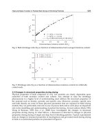
Fig. 7. Otoconium and SCC angular trajectory during the rotational maneuver.
Figure 6(a) shows the radial trajectory of the otoconium duri ng the maneuver whereas Fig-
ure 7 reports the angular tr ajectory of SCC and particle. A detail of the first part of the tr ajec-
tory is reported to highlight the detachment of the particle from the wall. Note that, during
the remaining part of the maneuver, the radial p osition of the otoconium remains close to the
SCC median radius (the oscillations are given by the uncertainties in the particle trajectory,
especially during the detaching phase).
Moreover, the dynamic system (1)-(2) can be inverted so as to design the SCC trajectory
(and, eventually, the necessary forces by means of (1)) when the desired o toconium tr ajec-
tory
[q
o
d
, ˙q
o
d
, ¨q
o
d
] is specified (where the subscript
d
stays for the desired trajectory instead
of the actual one).
By inversion of eq. (2), the acceler ation of the SCC can be then determined as:
¨q
c
d
= −M
†
co
(q
c
d
, q
o
d
)
[
M
o
(q
o
d
) ¨q
o
d
+ C
o
(q
o
d
, ˙q
o
d
) ˙q
o
d
+C
co
(q
o
d
, ˙q
o
d
, q
c
d
, ˙q
c
d
) ˙q
c
d
+ D(q
o
d
) ˙q
o
d
+ g(q
o
d
, q
c
d
) + b(q
o
d
, ˙q
o
d
)
]
(5)
where M
†
co
(q
c
d
, q
o
d
) indicates the pseud o-inverse of the matrix M
co
(q
c
d
, q
o
d
). This last equa-
tion defines an ODE problem that can be easily solved numerically by double integration of
(5) once the initial position/velocity of the SCC and the otoco nium trajectory are known.
It is important to note that, since the M
co
(q
c
d
, q
o
d
) is a 2 × 3 matr ix, its null space can be
defined as:
N
M
co
(q
c
d
, q
o
d
) = Null
{
M
co
(q
c
d
, q
o
d
)
}
=
rC
γβ
rS
γβ
1
(6)
Hence, the otoconium trajectory
[q
o
d
, ˙q
o
d
, ¨q
o
d
] can also be achieved with a different choice of
the SCC trajectory:
N
¨q
c
d
= ¨q
c
d
+
N
M
co
(q
c
d
, q
o
d
)λ (7)
where λ
∈ R is a suitable scalar coefficient used so as to select the desired SCC trajectory
in the space of all the possible ones. The definition of the value of λ can be made on the
base of different criteria. For instance the motion along a desired (penalized) direction can be
minimized or the SCC center can be kept inside a desired region. It is worth reminding that
(5) gives the minimum SCC acceler ation that produces the desired otoconium trajectory.
4. Robotic chair kinematic design
Section 3 theoretically proves that particular RM could be used in order to firstly detach
otoconia possibly stuck to the SCC’s walls and then to drive them out of the canals while
preventing further interactions with the canals’ soft tissues. These particular RM require a
rotation of an SCC along an axis passing through the point O
SCC
and perpendicular to the
x
B
y
B
plane (Figure 5).
Therefore, starting from the experience of Nakayama & Epley (2005) and on the basis of the
aforementioned consid erations, the aim of this section is to define the kinematic structure o f
a serial robot which could add more flex ibility in the execution of manually unfeasible R M
when compared to existing solutions (e.g. the OPS or human-carrying industrial robots). In
particular, the novel kinematic structure should be capable of practically applying the RM
proposed in Section 3 to each one of the six SCC.
In summary, the considered serial linkage complies with the following general specifica-
tions:
• Capability to perform all existing RM based on otoconia sedimentation;
• Capability to perform unlimited rotatio ns along the revolution axis of every SCC con-
ceived hereafter as a circular toroid;
• Capability to apply controlled inertial forces on every SCC (similarly to the inertial
forces applied during the Semont RM for treating the PC);
• Capability to reach a position where the moving chair would be easily accessible.
Other important issues are the safety and the ergonomics requirements as well as the overall
dimensions that must be acceptable for usage in a hospital environment. Mo reover, the psy-
chological impact of these kind of machines on the elderly do es not have to be undervalued.
To this resp ect, a closed structure (like in F igure 4) has been discarded preferring the use of
a serial manipulator. Despite the fact that serial structures are less rigid (and therefore less
accurate), they dispose of a better workspace, better accessibility and are more "acceptable"
by the patient in terms of human-robot interaction and user fri endliness.
On the other hand, the adoption of commercial manipulators, alike an anthropomorphic
robotic arm (Kuka, 2004), has been excluded as long as those structures do not guarantee
the desired degree of flexibili ty. In fact, the existence of joints’ limits and possible self collisi on
Taskanalysisandkinematicdesignofanovel
roboticchairforthemanagementoftop-shelfvertigo 633
−1.56
−1.58
−1.60
−1.62
−1
−2
−3
−4
−5
−6
0.50
1
0 20
40
60 80
Time [s]
β [rad]
(c)
(d)
(e)
(f)
(a) Otoconium angular trajectory.
0
1
22
0
1
2
3
4
5
6
0.50
1
0 20
40
60 80
Time [s]
γ [rad]
(c)
(d)
(e)
(f)
(b) SCC angular trajectory.
β
(c) Time = 0.0 [s].
γ
(d) Time = 0.5 [s].
γ
β
(e) Time = 40 [s].
γ
β
(f) Time = 83.11 [s].
Fig. 7. Otoconium and SCC angular trajectory during the rotational maneuver.
Figure 6(a) shows the radial trajectory of the otoconium during the maneuver whereas Fig-
ure 7 reports the angular tr ajectory of SCC and particle. A detail of the first part of the tr ajec-
tory is reported to highlight the detachment of the particle from the wall. Note that, during
the remaining part of the maneuver, the radial p osition of the otoconium remains close to the
SCC median radius (the oscillations are given by the uncertainties in the particle trajectory,
especially during the detaching phase).
Moreover, the dynamic system (1)-(2) can be inverted so as to design the SCC trajectory
(and, eventually, the necessary forces by means of (1)) when the desired o toconium tr ajec-
tory
[q
o
d
, ˙q
o
d
, ¨q
o
d
] is specified (where the subscript
d
stays for the desired trajectory instead
of the actual one).
By inversion of eq. (2), the acceleration of the SCC can be then determined as:
¨q
c
d
= −M
†
co
(q
c
d
, q
o
d
)
[
M
o
(q
o
d
) ¨q
o
d
+ C
o
(q
o
d
, ˙q
o
d
) ˙q
o
d
+C
co
(q
o
d
, ˙q
o
d
, q
c
d
, ˙q
c
d
) ˙q
c
d
+ D(q
o
d
) ˙q
o
d
+ g(q
o
d
, q
c
d
) + b(q
o
d
, ˙q
o
d
)
]
(5)
where M
†
co
(q
c
d
, q
o
d
) indicates the pseud o-inverse of the matrix M
co
(q
c
d
, q
o
d
). This last equa-
tion defines an ODE problem that can be easily solved numerically by double integration of
(5) once the initial position/velocity of the SCC and the otoco nium trajectory are known.
It is important to note that, since the M
co
(q
c
d
, q
o
d
) is a 2 × 3 matr ix, its null space can be
defined as:
N
M
co
(q
c
d
, q
o
d
) = Null
{
M
co
(q
c
d
, q
o
d
)
}
=
rC
γβ
rS
γβ
1
(6)
Hence, the otoconium trajectory
[q
o
d
, ˙q
o
d
, ¨q
o
d
] can also be achieved with a different choice of
the SCC trajectory:
N
¨q
c
d
= ¨q
c
d
+
N
M
co
(q
c
d
, q
o
d
)λ (7)
where λ
∈ R is a suitable scalar coefficient used so as to select the desired SCC trajectory
in the space of all the possible ones. The definition of the value of λ can be made on the
base of different criteria. For instance the motion along a desired (penalized) direction can be
minimized or the SCC center can be kept inside a desired region. It is worth reminding that
(5) gives the minimum SCC acceler ation that produces the desired otoconium trajectory.
4. Robotic chair kinematic design
Section 3 theoretically proves that particular RM could be used in order to firstly detach
otoconia possibly stuck to the SCC’s walls and then to drive them out of the canals while
preventing further interactions with the canals’ soft tissues. These particular RM require a
rotation of an SCC along an axis passing through the point O
SCC
and perpendicular to the
x
B
y
B
plane (Figure 5).
Therefore, starting from the experience of Nakayama & Epley (2005) and on the basis of the
aforementioned consid erations, the aim of this section is to define the kinematic structure o f
a serial robot which could add more flex ibility in the execution of manually unfeasible RM
when compared to existing solutions (e.g. the OPS or human-carrying industrial robots). In
particular, the novel kinematic structure should be capable of practically applying the RM
proposed in Section 3 to each one of the six SCC.
In summary, the considered serial linkage complies with the following general specifica-
tions:
• Capability to perform all existing RM based on otoconia sedimentation;
• Capability to perform unlimited rotatio ns along the revolution axis of every SCC con-
ceived hereafter as a circular toroid;
• Capability to apply controlled inertial forces on every SCC (similarly to the inertial
forces applied during the Semont RM for treating the PC);
• Capability to reach a position where the moving chair would be easily accessible.
Other important issues are the safety and the ergonomics requirements as well as the overall
dimensions that must be acceptable for usage in a hospital environment. Mo reover, the psy-
chological impact of these kind of machines on the elderly do es not have to be undervalued.
To this resp ect, a closed structure (like in F igure 4) has been discarded preferring the use of
a serial manipulator. Despite the fact that serial structures are less rigid (and therefore less
accurate), they dispose of a better workspace, better accessibility and are more "acceptable"
by the patient in terms of human-robot interaction and user fri endliness.
On the other hand, the adoption of commercial manipulators, alike an anthropomorphic
robotic arm (Kuka, 2004), has been excluded as long as those structures do not guarantee
the desired degree of flexibili ty. In fact, the existence of joints’ limits and possible self collisi on
RobotManipulators,TrendsandDevelopment634
highly restricts the feasible rotations along the SCC revolution axis (as it can be proven by
solving the inverse kinematic problems for such kind of manipulators). T herefore, differently
from the conceptual design of a "general purpose" manipulator, it is necessary to kinemati-
cally design an "on-purpose" machine capable of complying with the aforementioned specifi-
cations.
Precisely, the topological and dimensional synthesis of the serial linkag e has been achieved by
means of a simplified Task Based Design (TBD) technique (Kim, 1992).
As previously proposed in the liter ature (Chedmail & Ramstein, 1996; Chen & Burdick, 1995;
Kim & Khosla, 1993a; Yang & Chen, 2000), the TBD technique makes use of Genetic Algo-
rithms (GA) (Goldberg, 1989) in orde r to determine a robot’s kinematic structure which is
capable of performing a given set of tasks. The robot’s features to be determined include min-
imum number of degrees of freedom (MDOF), topology, and Denavit-Hartenberg parameters.
For instance, TBD has been proven effective in d etermining assemblies of modular robots op-
timally sui ted to perform a specific assignment. In the contest of modular ass emblies, both
the topology of the seri al chain and the links’ length must be treated as non continuous vari-
ables. Hence, it is necessary to use an optimization method, such as the GA, which is capable
of dealing with both hig hly nonlinear functions and discrete variables. In general, the opti-
mization problem itself can be posed as unconstrained (as in Chedmail & R amstein (1996)) or
constrained (as in Kim & Khosla (1993a)). In the latter case different constraints can be ap-
plied e.g. reachability, joint limits, obstacle avoidance, dexterity measures. In the same way,
the objective function to be optmized can be chosen in different manners such as workspace
maximization, manipulability index maxi mization, degrees of freedom (DOF) minimization,
mechanical constructability minimization. In this respect, global methods, as opposed to
progressive ones, try to accomplish an optimum design in one s tep only by minimizing a
weighted sum of the different requirements.
Similarly to the aforementioned example concerning mod ular robots, the optimi zation process
presented hereafter deals with discrete variables (i.e. manipulator topolog y and discretized
D-H parameters, see Section 4.2). The algorithm makes use of a progressive method which
meets consecutive constraints and successive optimized solutions. Note that the robot kine-
matic design can be further improved by using a continuous optimization method (Avilés
et al., 2000) once a possi ble robot’s topology has been finalized.
4.1 Specification of tasks
In order to apply TBD techniq ues, a series of tasks must be specified analytically. For this
purpose, three coordinate systems nee d to be defined (see Figure 8) as fol lows:
• (xyz)
B
, an absolute frame attached to the ground;
• (xyz)
CoG
, attached to the Center of Gravity (CoG) of the patient plus the moving chair,
hereafter considered as a rigid body: +z
CoG
(the yaw or horizontal rotation axis) is a
vertical axis pointing up, +x
CoG
(the roll axis) is perpendicular to +y
CoG
and +z
CoG
pointing anteriorly, and +y
CoG
(the pitch axis) points out the lef t ear;
• (xyz)
SCC
located on the intersecting point of the three revolution axes of each toroid,
here considering left SCC only. z
SCC
lies on the axis of the HC, y
SCC
lies on the ax is
of the PC, x
SCC
lies on the axis of the AC. SCC are considered as mutually orthogonal.
Another coordinate system attached to right SCC can be defined in the same manner.
As previously s tated (Figure 1(b)), the AC lie s on a plane inclined approximately 45
◦
with
respect to sagittal plane (xz)
CoG
, the PC l ies on a plane inclined 45
◦
but in opposite direction
and the HC is perpendicular to the other two canals and inclined approximately 15-20
◦
with
x
B
y
B
z
B
O
B
x
CoG
y
CoG
z
CoG
O
CoG
O
SCC
∆p
le ft
T
i,j
P
2
P
3
x
SCC
y
SCC
z
SCC
O
SCC
Posterior
Canal
Anterior
Canal
Horizontal
Canal
Vestibule
Utricle
Saccule
Cochlea
Fig. 8. Reference frames (solid lines) and relative homogeneous transformations (dotted lines).
respect to the horizontal plane (xy)
CoG
. The desired trajectories that fulfill the requirements
of the kinematic specifications are described by a finite set of tasks given as homogenous
transformation matrices between (xyz)
B
and (xyz)
CoG
.
In the remaining par t of the chapter the notations R
x
(·), R
y
(·) and R
z
(·) will be use d to
address 3
× 3 rotational matrices with respect to x-, y- and z-axis respectively whereas R
x
(·),
R
y
(·), R
z
(·) address the 4 × 4 homogeneous matrices associated with those same rotations.
Task set 1 – Rest position. This set contains only one task that depicts the chair in a
position which can be easily reached by the patient. The task is described by the following
homogeneous matrix:
T
1,1
=
0
R
z
(90
◦
)R
y
(45
◦
) 0
h
0 0 0 1
(8)
where h i ndi cates the desired CoG height from the ground.
Task set 2 – Eccentric rotation. This set contains all the tasks that describe an eccentric
rotation with variable radius.
T
2,i
=
ρ sin
(θ
i
)
R
y
(−20
◦
)R
z
(−θ
i
) ρ cos(θ
i
)
h
0 0 0 1
(9)
where ρ is the radius of the circular trajectories, T
2i
, i = 0 . . . N − 1 are N tasks describing
circular trajectories while maintaining the HC plane parallel to the ground, and θ
i
∈
π
2N
i
for i
= 0, , N − 1. Eccentric rotations can be used in order to apply controlled inertial forces
Taskanalysisandkinematicdesignofanovel
roboticchairforthemanagementoftop-shelfvertigo 635
highly restricts the feasible rotations along the SCC revolution axis (as it can be proven by
solving the inverse kinematic problems for such kind of manipulators). T herefore, differently
from the conceptual design of a "general purpose" manipulator, it is necessary to kinemati-
cally design an "on-purpose" machine capable of complying with the aforementioned specifi-
cations.
Precisely, the topological and dimensional synthesis of the serial linkag e has been achieved by
means of a simplified Task Based Design (TBD) technique (Kim, 1992).
As previously proposed in the liter ature (Chedmail & Ramstein, 1996; Chen & Burdick, 1995;
Kim & Khosla, 1993a; Yang & Chen, 2000), the TBD technique makes use of Genetic Algo-
rithms (GA) (Goldberg, 1989) in orde r to determine a robot’s kinematic structure which is
capable of performing a given set of tasks. The robot’s features to be determined include min-
imum number of degrees of freedom (MDOF), topology, and Denavit-Hartenberg parameters.
For instance, TBD has been proven effective in d etermining assemblies of modular robots op-
timally sui ted to perform a specific assignment. In the contest of modular ass emblies, both
the topology of the seri al chain and the links’ length must be treated as non continuous vari-
ables. Hence, it is necessary to use an optimization method, such as the GA, which is capable
of dealing with both hig hly nonlinear functions and discrete variables. In general, the opti-
mization problem itself can be posed as unconstrained (as in Chedmail & R amstein (1996)) or
constrained (as in Kim & Khosla (1993a)). In the latter case different constraints can be ap-
plied e.g. reachability, joint limits, obstacle avoidance, dexterity measures. In the same way,
the objective function to be optmized can be chosen in different manners such as workspace
maximization, manipulability index maxi mization, degrees of freedom (DOF) minimization,
mechanical constructability minimization. In this respect, global methods, as opposed to
progressive ones, try to accomplish an optimum design in one s tep only by minimizing a
weighted sum of the different requirements.
Similarly to the aforementioned example concerning mod ular robots, the optimi zation process
presented hereafter deals with discrete variables (i.e. manipulator topolog y and discretized
D-H parameters, see Section 4.2). The algorithm makes use of a progressive method which
meets consecutive constraints and successive optimized solutions. Note that the robot kine-
matic design can be further improved by using a continuous optimization method (Avilés
et al., 2000) once a possi ble robot’s topology has been finalized.
4.1 Specification of tasks
In order to apply TBD techniq ues, a series of tasks must be specified analytically. For this
purpose, three coordinate systems nee d to be defined (see Figure 8) as fol lows:
• (xyz)
B
, an absolute frame attached to the ground;
• (xyz)
CoG
, attached to the Center of Gravity (CoG) of the patient plus the moving chair,
hereafter considered as a rigid body: +z
CoG
(the yaw or horizontal rotation axis) is a
vertical axis pointing up, +x
CoG
(the roll axis) is perpendicular to +y
CoG
and +z
CoG
pointing anteriorly, and +y
CoG
(the pitch axis) points out the lef t ear;
• (xyz)
SCC
located on the intersecting point of the three revolution axes of each toroid,
here considering left SCC only. z
SCC
lies on the axis of the HC, y
SCC
lies on the ax is
of the PC, x
SCC
lies on the axis of the AC. SCC are considered as mutually orthogonal.
Another coordinate system attached to right SCC can be defined in the same manner.
As previously s tated (Figure 1(b)), the AC lie s on a plane inclined approximately 45
◦
with
respect to sagittal plane (xz)
CoG
, the PC l ies on a plane inclined 45
◦
but in opposite direction
and the HC is perpendicular to the other two canals and inclined approximately 15-20
◦
with
x
B
y
B
z
B
O
B
x
CoG
y
CoG
z
CoG
O
CoG
O
SCC
∆p
le ft
T
i,j
P
2
P
3
x
SCC
y
SCC
z
SCC
O
SCC
Posterior
Canal
Anterior
Canal
Horizontal
Canal
Vestibule
Utricle
Saccule
Cochlea
Fig. 8. Reference frames (solid lines) and relative homogeneous transformations (dotted lines).
respect to the horizontal plane (xy)
CoG
. The desired trajectories that fulfill the requirements
of the kinematic specifications are described by a finite set of tasks given as homogenous
transformation matrices between (xyz)
B
and (xyz)
CoG
.
In the remaining par t of the chapter the notations R
x
(·), R
y
(·) and R
z
(·) will be use d to
address 3
× 3 rotational matrices with respect to x-, y- and z-axis respectively whereas
R
x
(·),
R
y
(·), R
z
(·) address the 4 × 4 homogeneous matrices associated with those same rotations.
Task set 1 – Rest position. This set contains only one task that depicts the chair in a
position which can be easily reached by the patient. The task is described by the following
homogeneous matrix:
T
1,1
=
0
R
z
(90
◦
)R
y
(45
◦
) 0
h
0 0 0 1
(8)
where h i ndi cates the desired CoG height from the ground.
Task set 2 – Eccentric rotation. This set contains all the tasks that describe an eccentric
rotation with variable radius.
T
2,i
=
ρ sin
(θ
i
)
R
y
(−20
◦
)R
z
(−θ
i
) ρ cos(θ
i
)
h
0 0 0 1
(9)
where ρ is the radius of the circular trajectories, T
2i
, i = 0 . . . N − 1 are N tasks describing
circular trajectories while maintaining the HC plane parallel to the ground, and θ
i
∈
π
2N
i
for i
= 0, , N − 1. Eccentric rotations can be used in order to apply controlled inertial forces
RobotManipulators,TrendsandDevelopment636
on the HC (similarly to the stimuli arising during the Semount RM for PC treatment).
Task set 3 – Existin g clinical maneuvers. This task set collects the homogeneous ma-
trices describing existing manual maneuvers. These maneuvers (Boniver, 1990) can be
considered as a set of rotations along (xyz)
CoG
– axis. For instance, the task s et that describes
the Dix-Hallpike maneuver is given by the union of two concatenated subset with N/2 tasks
each. The two subsets are described by the following matrices:
T
(1)
3,i
=
0
R
z
(θ
i
) 0
h
0 0 0 1
(10)
T
(2)
3,i
= T
(1)
3,(N−1)/2
0
R
y
(θ
y
) 0
0
0 0 0 1
(11)
where θ
i
∈
−
π
2N
i
and θ
j
∈
3π
2N
j
for i, j = 0, ,
N−1
2
.
Task set 4 – Rotation along SCC axis. Task set 4 creates a circular path of (xyz)
CoG
around the revolution axis of each SCC. Consider left SCC first. Starting from (xyz)
CoG
in res t
position, let us define:
P
2
=
1 0 0 ∆ p
le ft,x
0 1 0 ∆p
le ft, y
0 0 1 ∆p
le ft, z
0 0 0 1
(12)
P
3
=
R
x
(Ω
HC
)R
z
(Ω
AC
) 0
3×1
0
1×3
1
(13)
where ∆p
le ft
= O
SCC
le f t
− O
CoG
= [∆p
le ft,x
∆p
le ft, y
∆p
le ft, z
]
t
is the vector that identifies
the position of xyz
SCC
le f t
with respect to the patient’s body frame, O
SCC
le f t
and O
CoG
are the
origins of (xyz)
SCC
and (xyz)
CoG
respectively, Ω
HC
and Ω
AC
are the orientations of HC and
AC defined as rotations along
(xyz)
CoG
P
2
.
Let us define the following matrix as a design parameter :
P
BO
=
1 0 0 0
0 1 0 0
0 0 1 h
+ ∆p
le ft, z
0 0 0 1
(14)
The rotations along the AC, HC and PC axis are respectively given by:
AC : T
4i
= P
BO
R
x
(θ
i
)(P
2
P
3
)
−1
(15)
HC : T
5i
= P
BO
R
y
(π/2)R
z
(θ
i
)(P
2
P
3
)
−1
(16)
PC : T
6i
= P
BO
R
z
(π/2)R
y
(θ
i
)(P
2
P
3
)
−1
(17)
where θ
i
∈
{
2πi
}
for i = 0, , N.
Supposing a perfect symmetry of the SCC canals with respect to the body’s sagittal plane, the
tasks concerning the right SCC can be obtained by setting
∆p
right
=
∆p
le ft,x
−∆p
le ft, y
∆p
le ft, z
T
(18)
At this stage, some design decisions have already been made:
• (xy)
B
rest position and patient orientation could be left free under certain limits,
whereas T
11
specifies a patient positioned over (xyz)
B
origin with a given orientation.
• There is no need to request a certain orientation along z
CoG
as the initial pose for the
set of existing manual RM whereas (xy)
B
and (xy)
CoG
are requested to be aligned as
Task se t 3 starts.
• The maneuvers in Task set 4 are conceived as rotations along a revolute pair with height
h
+ ∆p
le ft, z
from the ground when each set of rotations along each SCC could be ex-
ploited with different R-joints and in different spatial positions.
4.2 Problem Statement and Data Structures
The determination of the kinematic parameters for an optimized open-chain manipulator can
be regarded as a generi c optimization problem: minimize f(X), X
∈S, where S is the search
space of possible solution points, subjected to a cer tain number of constraints.
Because of the high-dimensioned parameter space, an heuristic algo rithm based on the theory
of GA has been implemented in order to find a possible solution. Within GA terminology,
the o bjective function to be optimized , f(X), is called fitness function, whereas an instance of a
possible solution X is called individual. The set of all the possible solutions at a given iteration
of the algorithm is called population. Let us define:
X
=
T
B
0
0
4×1
DH t ype
T
n
tool
0
4×1
, where :
[
DH type
]
=
α
1
a
1
ϑ
1
d
1
R or P
α
2
a
2
ϑ
2
d
2
R or P
.
.
.
.
.
.
.
.
.
.
.
.
.
.
.
0 0 0 0 F
.
.
.
.
.
.
.
.
.
.
.
.
.
.
.
α
n
a
n
ϑ
n
d
n
R or P
(19)
where X
(n+8)× 5
is a matrix representatio n of a serial robot, n is its number of DOF, T
B
0
, T
n
tool
are 4x 4 homogenous matrices, [DH type]
n×5
is an augmented matrix of D-H parameters with
an appended column indicating joint type. D-H parameters are listed as follows:
[α, a, ϑ, d].
Possible joints are 1-DOF joints (revolute (R) or prismatic (P)) and 0-DOF joints used as a slack
variable (F) to model a manipulator with less DOF than the maximum allowed.
According to the Denavit-Hartenberg (D-H) convention, T
B
0
and T
n
tool
indicate position and
orientation of robot base and tool with respect to the coordinate system attached to the first
and last movable joints respectively. Considering robot tool position coincident with the origin
of (xyz)
CoG
means that just the orientation part of T
n
tool
needs to be specified. The links’ length
is described as a discrete variable varying from zero to a predefined maximum value and then
divided into a finite number of parts. If the i-th joint is a revolute pair then ϑ
i
is a pose variable
and therefore not considered as a design parameter, if joint i-th is prismatic then d
i
is the pose
variable. Finally, if i-th joint is fixed, the corresponding row will be deleted in the evaluation
process.
Taskanalysisandkinematicdesignofanovel
roboticchairforthemanagementoftop-shelfvertigo 637
on the HC (similarly to the stimuli arising during the Semount RM for PC treatment).
Task set 3 – Existin g clinical ma neuvers. This task set col lects the homogeneous ma-
trices descr ibing exis ting manual maneuvers. These maneuvers (Boniver , 1990) can be
considered as a set of rotations along (xyz)
CoG
– axis. For instance, the task s et that describes
the Dix-Hallpike maneuver is given by the union of two concatenated subset with N/2 tasks
each. The two subsets are described by the following matrices:
T
(1)
3,i
=
0
R
z
(θ
i
) 0
h
0 0 0 1
(10)
T
(2)
3,i
= T
(1)
3,(N−1)/2
0
R
y
(θ
y
) 0
0
0 0 0 1
(11)
where θ
i
∈
−
π
2N
i
and θ
j
∈
3π
2N
j
for i, j = 0, ,
N−1
2
.
Task set 4 – Rotation along SCC axis. Task set 4 creates a circular path of (xyz)
CoG
around the revolution axis of each SCC. Consider left SCC first. Starting from (xyz)
CoG
in res t
position, let us define:
P
2
=
1 0 0 ∆ p
le ft,x
0 1 0 ∆p
le ft, y
0 0 1 ∆p
le ft, z
0 0 0 1
(12)
P
3
=
R
x
(Ω
HC
)R
z
(Ω
AC
) 0
3×1
0
1×3
1
(13)
where ∆p
le ft
= O
SCC
le f t
− O
CoG
= [∆p
le ft,x
∆p
le ft, y
∆p
le ft, z
]
t
is the vector that identifies
the position of xyz
SCC
le f t
with respect to the patient’s body frame, O
SCC
le f t
and O
CoG
are the
origins of (xyz)
SCC
and (xyz)
CoG
respectively, Ω
HC
and Ω
AC
are the orientations of HC and
AC defined as rotations along
(xyz)
CoG
P
2
.
Let us define the following matrix as a design parameter :
P
BO
=
1 0 0 0
0 1 0 0
0 0 1 h
+ ∆p
le ft, z
0 0 0 1
(14)
The rotations along the AC, HC and PC axis are respectively given by:
AC : T
4i
= P
BO
R
x
(θ
i
)(P
2
P
3
)
−1
(15)
HC : T
5i
= P
BO
R
y
(π/2)R
z
(θ
i
)(P
2
P
3
)
−1
(16)
PC : T
6i
= P
BO
R
z
(π/2)R
y
(θ
i
)(P
2
P
3
)
−1
(17)
where θ
i
∈
{
2πi
}
for i = 0, , N.
Supposing a perfect symmetry of the SCC canals with respect to the body’s sagittal plane, the
tasks concerning the right SCC can be obtained by setting
∆p
right
=
∆p
le ft,x
−∆p
le ft, y
∆p
le ft, z
T
(18)
At this stage, some design decisions have already been made:
• (xy)
B
rest position and patient orientation could be left free under certain limits,
whereas T
11
specifies a patient positioned over (xyz)
B
origin with a given orientation.
• There is no need to request a certain orientation along z
CoG
as the initial pose for the
set of existing manual RM whereas (xy)
B
and (xy)
CoG
are requested to be aligned as
Task se t 3 starts.
• The maneuvers in Task set 4 are conceived as rotations along a revolute pair with height
h
+ ∆p
le ft, z
from the ground when each set of rotations along each SCC could be ex-
ploited with different R-joints and in different spatial positions.
4.2 Problem Statement and Data Structures
The determination of the kinematic parameters for an optimized open-chain manipulator can
be regarded as a generi c optimization problem: minimize f(X), X
∈S, where S is the search
space of possible solution points, subjected to a cer tain number of constraints.
Because of the high-dimensioned parameter space, an heuristic algo rithm based on the theory
of GA has been implemented in order to find a possible solution. Within GA terminology,
the o bjective function to be optimized , f(X), is called fitness function, whereas an instance of a
possible solution
X is called individual. The set of all the possible solutions at a given iteration
of the algorithm is called population. Let us define:
X
=
T
B
0
0
4×1
DH t ype
T
n
tool
0
4×1
, where :
[
DH type
]
=
α
1
a
1
ϑ
1
d
1
R or P
α
2
a
2
ϑ
2
d
2
R or P
.
.
.
.
.
.
.
.
.
.
.
.
.
.
.
0 0 0 0 F
.
.
.
.
.
.
.
.
.
.
.
.
.
.
.
α
n
a
n
ϑ
n
d
n
R or P
(19)
where X
(n+8)× 5
is a matrix representatio n of a serial robot, n is its number of DOF, T
B
0
, T
n
tool
are 4x 4 homogenous matrices, [DH type]
n×5
is an augmented matrix of D-H parameters with
an appended column indicating joint type. D-H parameters are listed as follows:
[α, a, ϑ, d].
Possible joints are 1-DOF joints (revolute (R) or pris matic (P)) and 0-DOF joints used as a slack
variable (F) to model a manipulator with less DOF than the maximum allowed.
According to the Denavit-Hartenberg (D-H) convention, T
B
0
and T
n
tool
indicate position and
orientation of robot base and tool with respect to the coordinate system attached to the first
and last movable joints respectively. Considering robot tool position coincident with the origin
of (xyz)
CoG
means that just the orientation part of T
n
tool
needs to be specified. The links’ length
is described as a discrete variable varying from zero to a predefined maximum value and then
divided into a finite number of parts. If the i-th joint is a revolute pair then ϑ
i
is a pose variable
and therefore not considered as a design parameter, if joint i-th is prismatic then d
i
is the pose
variable. Finally, if i-th joint is fixed, the corresponding row will be deleted in the evaluation
process.
RobotManipulators,TrendsandDevelopment638
The candidate robots generation is based on a set of heuristic rules s imilar to those found in
(Kim & Khosla, 1993a):
• Kinematic simplicity: α and ϑ (whenever the latest is considered as a design variable)
can assume values belonging to the set
[0, ±π/2, π]. Concerning R-joints, at least one
of the two variables representing length
(a, d) is set to zero.
• Redundancy avoidan ce: R-joints described by D-H parameters of the type [0, 0, ϑ, d]
cannot be followed by another R-joint, thus avoiding solutions where two revolute
joints are mounted on the same axis.
4.3 Evaluation Procedure
The des ign process of the serial link chain is automated through an optimization proced ure
which allows a less subjective decision making progression and increases the performance
with respect to an objective function defined in order to assess the benefit of a solution (Fig-
ure 9).
The type of searching method depends most of all on the type of var iables to be dealt with
(continuous, discrete or mixed) and on the type of problem (constrained or unconstrained). In
this chapter, a GA is used to solve a constrained optimization process on the discrete variable.
Exhaustive search techniques, which basically measures the benefit of each possible individ-
ual, could be used to find the exact optimal solution; whether this technique would be better
suited for a specified problem is just a matter of computational time. Probabilistic search tech-
niques, such as GA or simulated annealing, become a good choice when the search space is
extremely large.
At each step a GA creates a new population of individuals using the individual or data struc-
tures of the current generation. It basically scores each cur rent individual computing its fitness
value; it then selects a set of parents based on their fitness (selection process ) and produces a
new generation starting from this given set of i ndi viduals. Individuals of the new generation
are either taken from the selected parents without any change (elitism), randomly changing a
single parent (mutation) or combining vector entries of different parents within the same class
of substructures (i.e. avoiding as a result an individual with different data structure from the
one reported). The algo rithm stops when a given stopping criteria is met. In this chapter the
only specified criteria is a limit on the number of generations.
Given a set of tasks, it is stated that a reachability constraint (RC) must be satisfied. For a
particular task, the RC is said to be satisfied if: 1) There exis ts a solution of the inverse kine-
matic problem (IK) which presents a positional error norm and an orientational er ror norm
lower than an appropriate threshold (Kim & Khosla, 1993b) 2) Such solution is found within
a certain number of iterations. As long as the structure of the manipulator is not yet defined
and the serial chain can assume a very high number of configurations, a numerical method to
solve the IK problem is used; reference is made to the singularity robust IK method proposed
by L. Kelmar and P. K. Khosla (Kelmar & Khosl a, 1990). If the RC is not satisfied the fitness
value is set to a very large number.
4.4 Design stages
The GA-based optimization procedure has been splitted in two different stages (Figure 9).
4.4.1 Minimized Degrees-of-Freedom approach (MDOF)
In the first design stage the fitness value is simply the number of DOF of the manipulator
regardless of joints being revolute or prismatic. IK is computed for every task in series on
Task specification
(set of homogeneous matrices)
Minimum degrees
of freedom
(MDOF)
Minimize mechanical
constructability
Set of possible solutions
Current population
Inverse kinematic
Task specification
Satisfy?
Ye s
No
Compute Fitness
(Genetic Algorithm)
Set Fitness to ver y
large number
Fitness Value
Two
− Step Optimization
Algorithm
Evaluation Algorithm
Fig. 9. Desi gn steps and evaluation procedure.
structures where rows concerning fixed joints are previously deleted. If the RC is not satisfied
the fitness value is set to a very large number and successive tasks are not evaluated. Prior to
IK calculation, which is the most time consuming procedure, it is verified that:
r
i
−
n
∑
j=0
l
j
< 0 i = 1, , N
TOT
where
l
j
≤ L
max
if j − th joint is revolute
l
j
= 2L
max
if j − th joint is prismatic
(20)
where N
TOT
is the total number of tasks, r
i
is the Euclidian distance of i- th task from the robot
base and l
j
is j-th link length. l
0
=
O
0
− O
B
(O
0
and O
k
are supposed coincident, where O
k
is the origin of (xyz)
k
according to Chocron & Bidaud (1997)). After IK, i-th RC is considered
not satisfied if:
a
2
j
+
∆d
2
j,max
> 2L
max
(21)
where ∆d
j,max
= |d
j,max
− d
j,min
| (i.e. d uring motio n the prismatic joint has traveled a distance
greater than 2L
max
, its initial length being set to a
j
).
The result of this design step is the minimum number of DOF necessary to perform task spec-
ifications meaning that the algorithm has found an individual X that represents a n-DOF kine-
matic structure able to perform every pose.
4.4.2 Mechanical Constructability Minimization.
The aim of this second d esign stage is the minimization of total link length and therefore of
total robot’s mass. The fitness function is set to:
F
(X) =
n
∑
j=0
l
j
, where
l
j
=
a
2
j
+ d
2
j
if j − th joint is revolute
l
j
=
a
2
j
+
∆d
2
j,max
if j
− th joint is prismatic
(22)
Taskanalysisandkinematicdesignofanovel
roboticchairforthemanagementoftop-shelfvertigo 639
The candidate robots generation is based on a set of heuristic rules s imilar to those found in
(Kim & Khosla, 1993a):
• Kinematic simplicity: α and ϑ (whenever the latest is considered as a design variable)
can assume values belonging to the set
[0, ±π/2, π]. Concerning R-joints, at least one
of the two variables representing length
(a, d) is set to zero.
• Redundancy avoidan ce: R-joints described by D-H parameters of the type [0, 0, ϑ, d]
cannot be followed by another R-joint, thus avoiding solutions where two revolute
joints are mounted on the same axis.
4.3 Evaluation Procedure
The des ign process of the serial link chain is automated through an optimization proced ure
which allows a less subjective decision making progression and increases the performance
with respect to an objective function defined in order to assess the benefit of a solution (Fig-
ure 9).
The type of searching method depends most of all on the type of var iables to be dealt with
(continuous, discrete or mixed) and on the type of problem (constrained or unconstrained). In
this chapter, a GA is used to solve a constrained optimization process on the discrete variable.
Exhaustive search techniques, which basically measures the benefit of each possible individ-
ual, could be used to find the exact optimal solution; whether this technique would be better
suited for a specified problem is just a matter of computational time. Probabilistic search tech-
niques, such as GA or simulated annealing, become a good choice when the search space is
extremely large.
At each step a GA creates a new population of individuals using the individual or data struc-
tures of the current generation. It basically scores each cur rent individual computing its fitness
value; it then selects a set of parents based on their fitness (selection process ) and produces a
new generation starting from this given set of i ndi viduals. Individuals of the new generation
are either taken from the selected parents without any change (elitism), randomly changing a
single parent (mutation) or combining vector entries of different parents within the same class
of substructures (i.e. avoiding as a result an individual with different data structure from the
one reported). The algo rithm stops when a given stopping criteria is met. In this chapter the
only specified criteria is a limit on the number of generations.
Given a set of tasks, it is stated that a reachability constraint (RC) must be satisfied. For a
particular task, the RC is said to be satisfied if: 1) There exis ts a solution of the inverse kine-
matic problem (IK) which presents a positional error norm and an orientational er ror norm
lower than an appropriate threshold (Kim & Khosla, 1993b) 2) Such solution is found within
a certain number of iterations. As long as the structure of the manipulator is not yet defined
and the serial chain can assume a very high number of configurations, a numerical method to
solve the IK problem is used; reference is made to the singularity robust IK method proposed
by L. Kelmar and P. K. Khosla (Kelmar & Khosl a, 1990). If the RC is not satisfied the fitness
value is set to a very large number.
4.4 Design stages
The GA-based optimization procedure has been splitted in two different stages (Figure 9).
4.4.1 Minimized Degrees-of-Freedom approach (MDOF)
In the first design stage the fitness value is simply the number of DOF of the manipulator
regardless of joints being revolute or prismatic. IK is computed for every task in series on
Task specification
(set of homogeneous matrices)
Minimum degrees
of freedom
(MDOF)
Minimize mechanical
constructability
Set of possible solutions
Current population
Inverse kinematic
Task specification
Satisfy?
Ye s
No
Compute Fitness
(Genetic Algorithm)
Set Fitness to ver y
large number
Fitness Value
Two
− Step Optimization
Algorithm
Evaluation Algorithm
Fig. 9. Desi gn steps and evaluation procedure.
structures where rows concerning fixed joints are previously deleted. If the RC is not satisfied
the fitness value is set to a very large number and successive tasks are not evaluated. Prior to
IK calculation, which is the most time consuming procedure, it is verified that:
r
i
−
n
∑
j=0
l
j
< 0 i = 1, , N
TOT
where
l
j
≤ L
max
if j − th joint is revolute
l
j
= 2L
max
if j − th joint is prismatic
(20)
where N
TOT
is the total number of tasks, r
i
is the Euclidian distance of i- th task from the robot
base and l
j
is j-th link length. l
0
=
O
0
− O
B
(O
0
and O
k
are supposed coincident, where O
k
is the origin of (xyz)
k
according to Chocron & Bidaud (1997)). After IK, i-th RC is considered
not satisfied if:
a
2
j
+
∆d
2
j,max
> 2L
max
(21)
where ∆d
j,max
= |d
j,max
− d
j,min
| (i.e. d uring motio n the prismatic joint has traveled a distance
greater than 2L
max
, its initial length being set to a
j
).
The result of this design step is the minimum number of DOF necessary to perform task spec-
ifications meaning that the algorithm has found an individual
X that represents a n-DOF kine-
matic structure able to perform every pose.
4.4.2 Mechanical Constructability Minimization.
The aim of this second d esign stage is the minimization of total link length and therefore of
total robot’s mass. The fitness function is set to:
F
(X) =
n
∑
j=0
l
j
, where
l
j
=
a
2
j
+ d
2
j
if j − th joint is revolute
l
j
=
a
2
j
+
∆d
2
j,max
if j
− th joint is prismatic
(22)
RobotManipulators,TrendsandDevelopment640
−1
−0.5
0
0.5
1
−1
−0.5
0
0.5
1
0
0.5
1
1.5
2
[m]
[m]
[m]
Joint
6
Joint
1
X
B
Y
B
Z
B
O
B
X
CoG
Y
CoG
Z
CoG
O
CoG
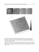
Fig. 10. Schematic representation of the best solution founded via GA optimization: revolute
and prismatic joints are depicted as cylinders and boxes respectively.
At this design stage fixed joints are not allowed and must be removed before the procedure
can start.
4.5 Simulation Results
The algorithm is imp lemented using the Matlab Genetic Alg orithm and the Direct Search
Too lbox. RobotiCad Toolbox for Matlab (Falconi & Melchiorri, 2007; Falconi et al., 2006) has
been used as IK solver and visualization tool.
Simulations are run for a population size of 50 individuals-200 generations. For a given task,
the implemented IK solver fails if the number of iterations exceeds 500 or succeeds if both po-
sitional and orientational error norms are lower than 10
−3
. Table 2 reports task specification
parameters. Fitness value for not feasible structures was set to 9 during the first design stage
and to 100 during the second one.
Symbol ∆p
le ft
[m] Ω
HC
Ω
AC
h [m] L
max
[m] α[rad] N
TOT
ρ[m]
Quantity
0.1
0.1
0.75
20
◦
45
◦
0.75 2 [0, ±π/2, π] 76 0.5 − 1
Table 2. Input Variables
α [rad] a [m] ϑ [rad] d [m] R/P
Joint 1 π/2 0.00 ϑ
1
1.20 R
Joint 2 3π/2 0.10 ϑ
2
0 R
Joint 3 3π/2 0.00 π d
3
P
Joint 4 3π/2 0.00 ϑ
4
0 R
Joint 5 3π/2 0.00 ϑ
5
0.20 R
Joint 6 π 0.00 ϑ
6
0 R
Table 3. Best solution’s Denavith-Hartenberg parameters and joint types.
The best found solution is reported in Table 3, the matrices T
B
0
and T
n
tool
being two identity
matrices i. e. the absolute frame and the robot’s base frame are coincident and the frame at-
tached to the last link is coincident with the robot’s tool frame. The solution’s representation
is depicted in Figure 10. The proposed serial linkage is topologically similar to a Stanford
manipulator prese nting a particular wrist (not spherical). As long as no obstacle avoidance
has been considered, the only useful information that can be found by the MDOF approach is
that the specified set of tasks could not be accomplished by less than 6-DOF robots or that the
GA couldn’t find such solution applying the given set of heuristic rules (mechanical simplicity
and redundancy avoidance).
A conceptual design of the six-DOF robot (patented by Berselli et al. (2007)) is depicted in
Figure 11(a) whereas Figure 11(b) shows the manipulator performing a rotation along the rev-
olution axis of the ri ght AC.
In particular, the last two joints are used to replicate every existing manual maneuver and the
first joint is use d to apply controlled inertial forces (similar to the stimuli arising during the
Semount RM) o n the HC via eccentric rotation of the patient. The other DOF are used to con-
trol the trajectory of the otoconia within an SCC performing full rotation along the revolution
axis of every SCC (as shown in Section 3). At this stage no care was taken concerning dynamic
and structural analysis and optimization. Further steps for the development of a working pro-
totype include decision making of possible motors, gears, bearings and couplings as wel l as
cabling and material selection.
5. Discussion and future work
Given the manipulator’s kinematic model reported in Tab. 3, the movements of the SCC and
of the patient body can be easily related to the motion of the manipulator. In particular, the
dynamic mod el of eqs. (1) and (2) allows the study of the otoconium movements during ma-
neuvers that can be potentially performed by the proposed serial linkage. In fact, the chosen
kinematical structure allows to achieve unlimited rotations along the revolution axis of every
SCC and to control the SCC planar moveme nt in the x and y directions (Figure 5). Obviously,
this kind of RM cannot be manually achieved.
Taskanalysisandkinematicdesignofanovel
roboticchairforthemanagementoftop-shelfvertigo 641
−1
−0.5
0
0.5
1
−1
−0.5
0
0.5
1
0
0.5
1
1.5
2
[m]
[m]
[m]
Joint
6
Joint
1
X
B
Y
B
Z
B
O
B
X
CoG
Y
CoG
Z
CoG
O
CoG
Fig. 10. Schematic representation of the best solution founded via GA optimization: revolute
and prismatic joints are depicted as cylinders and boxes respectively.
At this design stage fixed joints are not allowed and must be removed before the procedure
can start.
4.5 Simulation Results
The algorithm is imp lemented using the Matlab Genetic Alg orithm and the Direct Search
Too lbox. RobotiCad Toolbox for Matlab (Falconi & Melchiorri, 2007; Falconi et al., 2006) has
been used as IK solver and visualization tool.
Simulations are run for a population size of 50 individuals-200 generations. For a given task,
the implemented IK solver fails if the number of iterations exceeds 500 or succeeds if both po-
sitional and orientational error norms are lower than 10
−3
. Table 2 reports task specification
parameters. Fitness value for not feasible structures was set to 9 during the first design stage
and to 100 during the second one.
Symbol ∆p
le ft
[m] Ω
HC
Ω
AC
h [m] L
max
[m] α[rad] N
TOT
ρ[m]
Quantity
0.1
0.1
0.75
20
◦
45
◦
0.75 2 [0, ±π/2, π] 76 0.5 − 1
Table 2. Input Variables
α [rad] a [m] ϑ [rad] d [m] R/P
Joint 1 π/2 0.00 ϑ
1
1.20 R
Joint 2 3π/2 0.10 ϑ
2
0 R
Joint 3 3π/2 0.00 π d
3
P
Joint 4 3π/2 0.00 ϑ
4
0 R
Joint 5 3π/2 0.00 ϑ
5
0.20 R
Joint 6 π 0.00 ϑ
6
0 R
Table 3. Best solution’s Denavith-Hartenberg parameters and joint types.
The best found solution is reported in Table 3, the matrices T
B
0
and T
n
tool
being two identity
matrices i. e. the absolute frame and the robot’s base frame are coincident and the frame at-
tached to the last link is coincident with the robot’s tool frame. The solution’s representation
is depicted in Figure 10. The proposed serial linkage is topologically similar to a Stanford
manipulator prese nting a particular wrist (not spherical). As long as no obstacle avoidance
has been considered, the only useful information that can be found by the MDOF approach is
that the specified set of tasks could not be accomplished by less than 6-DOF robots or that the
GA couldn’t find such solution applying the given set of heuristic rules (mechanical simpli city
and redundancy avoidance).
A conceptual design of the six-DOF robot (patented by Berselli et al. (2007)) is depicted in
Figure 11(a) whereas Fi gure 11(b) shows the manipulator performing a rotation along the rev-
olution axis of the right AC.
In particular, the last two joints are used to replicate every existing manual maneuver and the
first joint is use d to apply controlled inertial forces (similar to the stimuli aris ing during the
Semount RM) o n the HC via eccentric rotation of the patient. The other DOF are used to con-
trol the trajectory of the otoconia within an SCC performing full rotation along the revolution
axis of every SCC (as shown in Section 3). At this stage no care was taken concerning dynamic
and structural analysis and optimization. Further steps for the development of a working pro-
totype include decision making of possible motors, gears, bearings and couplings as wel l as
cabling and material selection.
5. Discussion and future work
Given the manipulator’s kinematic model reported in Tab. 3, the movements of the SCC and
of the patient body can be easily related to the motion of the manipulator. In particular, the
dynamic mod el of eqs. (1) and (2) allo ws the study of the otoconium movements during ma-
neuvers that can be potentially performed by the proposed serial linkage. In fact, the chosen
kinematical structure allows to achieve unlimited rotations along the revolution axis of every
SCC and to control the SCC planar moveme nt in the x and y directions (Figure 5). Obviously,
this kind of RM cannot be manually achieved.
RobotManipulators,TrendsandDevelopment642
Joint6 Joint1
(a) Manipulator conceptual design. (b) Rotation along right AC axis.
Fig. 11. Manipulator performing tasks.
Note that the choice of suitable strategies for controlling the manipulator (Siciliano & Khatib,
2008) makes it possible to assume that the dynamics of the patient’s body movements is de-
scribed by eq. (1). Therefore, M
c
can be assume d to be the identity matrix. This assumption
implies that all the spur ious effects that deviate the behavior of the SCC dynamics with re-
spect to eq. (1) must be compensated by the manipulator controller.
It is clear that the otoconium trajectory must be carefully selected in order to achieve a SCC
motion that: 1) It is toler able by the patient (in terms of imposed acceleration); 2) It does not
overcome the manipulator limits (in terms of possible pose and velo ci ty /acceleration).
At last, it should be pointed out that eq. (1) is useful when determining the forces which are
necessary to accomplish a given RM once the otoconium tr ajectory and the patient parameters
are known.
6. Conclusions
This chapter proves the usability of a simplified Task Based Design technique as an aid in the
synthesis of serial linkages and presents a novel robotic chair to be used in diagnosing and
treating BPPV. The spe ci fication of the tasks to be perfo rmed by the chair has been based upon
direct specifications given by well-trained doctors or upon the observation that BPPV therapy
could be improved once the limits of the manual maneuvers are overcome. Supposing that it
is possible to control the motion of a SCC along a plane per p endicular to the SCC revolution
axis, an idealized BPPV’s dynamic model has been used to show that manually unfeasible
maneuvers can be optimized for better treating positional vertigo.
Therefore, as a response to a series of new requirements, the p resented novel robotic chair is
capable o f performing both existing manual maneuver based on otoconia sedimentation and
unlimited rotations along the revolution axi s of every SCC while controlling the SCC planar
motion.
To the best of the author’s knowledge, the propos ed solution kinematically differs from any
existing de vice and could be used to enhance the rate of success of BPPV non-invasive thera-
pies.
7. Acknowledgment
The authors gratefully acknowledge MedRob Project fund ed by the University of Bologna for
supporting this work and the contribution of Prof. Giovanni Carlo Modugno and Dr. Cristina
Brandolini from St. Orsola Hospital, University of Bologna.
8. References
Arnold, B., Jäger, L. & Grevers, G. (1997). Visualization of inner ear structures by three-
dimensional high-resolution magnetic resonance imaging, Otology and Neurotology
17: 935–939.
Avilés, R., Vallejo, J., Ajuria, G. & Agirrebeitia, J. (2000). Second order methods for the op-
timum synthesis of multibody systems, Structural and Multidisciplinary Optimization
19: 192–203.
Baloh, R. W., Sloane, P. D. & Honrubia, V. (1989). Quantitative vestibular function testing in
elderly patients with dizziness, Ear Nose Throat J. 6: 1–16.
Berselli, G., Vassura, G. & Modugno, G. C. (2007). A serial robot for the handling of human
body to be used in the diagnosis and treatment of vestibular lithiasis, Italian Patent
No. RM2007A000252, Issued for University of Bologna. .
Boniver, R. (1990). Benign paroxysmal positional vertig o. state of the art, Acta Oto-rhino-
laryngologica Belgica 52(4): 281–289.
Brandt, T. & Daroff, R. B. (1980). Physical therapy for benign paroxysmal positional vertigo,
Arch. Otolaryngol. 106: 484–485.
Chedmail, P. & Ramstein, E. (1996). Robot mechanisms synthesis and genetic algorithms,
Proceedings of the IEEE International Conference on Robotics and Automation, pp. 3466–
3471.
Chen, M. & Burdick, J. (1995). Determining task optimal robot assembly configurations, Pro-
ceedings of the IEEE International Conference on Robotics and Automation, pp. 132–137.
Chocron, O. & Bidaud, P. (1997). Genetic design of 3d modular manipulators, Proceedings of
the IEEE Internati onal Conference on Robotics and Automation, Vol. 1, pp. 223–228.
Della Santina, C., Potyagaylo, V., Migliaccio, A., Minor, L. B. & Carey, J. P. (2005). Orien-
tation of human semicircular canals measured by three-dimensio nal multiplanar ct
reconstruction, Journal of the Association for Research in Otolaryngology 68: 935–939.
Dix, M. & Hallpike, C. (1952). Pathology, symptomatology and diagnosis of certain common
disorders of the vestibular system, Ann. Otol. Rhinol. Laryngol. 61: 987–1016.
Epley, J. M. (1992). The canalith repositioning procedure - for treatment of benign paroxysmal
positional vertigo, Otolaryngol. Head Neck Surg. 107: 399–404.
Falconi, R. & Melchiorri, C. (2007). Roboticad, an educational tool for robotics, 17th IFAC World
Congress, pp. 9111–9116.
Falconi, R., Melchiorri, C., Macchelli, A. & Biagiotti, L. (2006). Roboticad: a matlab toolbox
for robot manipulators, 8th International IFAC Symposium on Robot Control (Syroco),
pp. 9111–9116.
Taskanalysisandkinematicdesignofanovel
roboticchairforthemanagementoftop-shelfvertigo 643
Joint6 Joint1
(a) Manipulator conceptual design. (b) Rotation along right AC axis.
Fig. 11. Manipulator performing tasks.
Note that the choice of suitable strategies for controlling the manipulator (Siciliano & Khatib,
2008) makes it possible to assume that the dynamics of the patient’s body movements is de-
scribed by eq. (1). Therefore, M
c
can be assume d to be the identity matrix. This assumption
implies that all the spur ious effects that deviate the behavior of the SCC dynamics with re-
spect to eq. (1) must be compensated by the manipulator controller.
It is clear that the otoconium trajectory must be carefully selected in order to achieve a SCC
motion that: 1) It is toler able by the patient (in terms of imposed acceleration); 2) It does not
overcome the manipulator limits (in terms of possible pose and velo ci ty /acceleration).
At last, it should be pointed out that eq. (1) is useful when determining the forces which are
necessary to accomplish a given RM once the otoconium tr ajectory and the patient parameters
are known.
6. Conclusions
This chapter proves the usability of a simplified Task Based Design technique as an aid in the
synthesis of serial linkages and presents a novel robotic chair to be used in diagnosing and
treating BPPV. The spe ci fication of the tasks to be perfo rmed by the chair has been based upon
direct specifications given by well-trained doctors or upon the observation that BPPV therapy
could be improved once the limits of the manual maneuvers are overcome. Supposing that it
is possible to control the motion of a SCC along a plane per p endicular to the SCC revolution
axis, an idealized BPPV’s dynamic model has been used to show that manually unfeasible
maneuvers can be optimized for better treating positional vertigo.
Therefore, as a response to a series of new requirements, the p resented novel robotic chair is
capable o f performing both existing manual maneuver based on otoconia sedimentation and
unlimited rotations along the revolution axi s of every SCC while controlling the SCC planar
motion.
To the best of the author’s knowledge, the propos ed solution kinematically differs from any
existing de vice and could be used to enhance the rate of success of BPPV non-invasive thera-
pies.
7. Acknowledgment
The authors gratefully acknowledge MedRob Project fund ed by the University of Bologna for
supporting this work and the contribution of Prof. Giovanni Carlo Modugno and Dr. Cristina
Brandolini from St. Orsola Hospital, University of Bologna.
8. References
Arnold, B., Jäger, L. & Grevers, G. (1997). Visualization of inner ear structures by three-
dimensional high-resolution magnetic resonance imaging, Otology and Neurotology
17: 935–939.
Avilés, R., Vallejo, J., Ajuria, G. & Agirrebeitia, J. (2000). Second order methods for the op-
timum synthesis of multibody systems, Structural and Multidisciplinary Optimization
19: 192–203.
Baloh, R. W., Sloane, P. D. & Honrubia, V. (1989). Quantitative vestibular function testing in
elderly patients with dizziness, Ear Nose Throat J. 6: 1–16.
Berselli, G., Vassura, G. & Modugno, G. C. (2007). A serial robot for the handling of human
body to be used in the diagnosis and treatment of vestibular lithiasis, Italian Patent
No. RM2007A000252, Issued for University of Bologna. .
Boniver, R. (1990). Benign paroxysmal positional vertig o. state of the art, Acta Oto-rhino-
laryngologica Belgica 52(4): 281–289.
Brandt, T. & Daroff, R. B. (1980). Physical therapy for benign paroxysmal positional vertigo,
Arch. Otolaryngol. 106: 484–485.
Chedmail, P. & Ramstein, E. (1996). Robot mechanisms synthesis and genetic algorithms,
Proceedings of the IEEE International Conference on Robotics and Automation, pp. 3466–
3471.
Chen, M. & Burdick, J. (1995). Determining task optimal robot assembly configurations, Pro-
ceedings of the IEEE International Conference on Robotics and Automation, pp. 132–137.
Chocron, O. & Bidaud, P. (1997). Genetic design of 3d modular manipulators, Proceedings of
the IEEE Internati onal Conference on Robotics and Automation, Vol. 1, pp. 223–228.
Della Santina, C., Potyagaylo , V., Migliaccio, A., Minor, L. B. & Carey, J. P. (2005). Orien-
tation of human semicircular canals measured by three-dimensio nal multiplanar ct
reconstruction, Journal of the Association for Research in Otolaryngology 68: 935–939.
Dix, M. & Hallpike, C. (1952). Pathology, symptomatology and diagnosis of certain common
disorders of the vestibular system, Ann. Otol. Rhinol. Laryngol. 61: 987–1016.
Epley, J. M. (1992). The canalith repositioning procedure - for treatment of benign paroxysmal
positional vertigo, Otolaryngol. Head Neck Surg. 107: 399–404.
Falconi, R. & Melchiorri, C. (2007). Roboticad, an educational tool for robotics, 17th IFAC World
Congress, pp. 9111–9116.
Falconi, R., Melchiorri, C., Macchelli, A. & Biagiotti, L. (2006). Roboticad: a matlab toolbox
for robot manipulators, 8th International IFAC Symposium on Robot Control (Syroco),
pp. 9111–9116.
RobotManipulators,TrendsandDevelopment644
Froehling, D. A., Silverstein, M. D., Mohr, D. N., Beatty, C., Offord, K. P. & Ballard, D. J. (1991).
Benign pos itional vertigo: Incidence and prognosi s in a population-based study in
olmsted county, Mi nnesota. Mayo. Clin. Proc., Vol. 66, pp. 596–601.
Goldberg, D. (1989). Genetic Algorithm in Search, Optimization and Machine Learning, Ad dison-
Wesley.
Hain, T. C., Squires, T. M. & Stone, H. A. ( 2005). Clinical implications of a mathematical model
of benign paroxysmal positional vertigo.
Honrubia, V., Bell, T. S., Harris, M. R., Baloh, R. W. & Fisher, L. M. (1996). Quantitative eval-
uation of dizziness character istics and impact on quality of life, Am. J. Otol., Vol. 17,
pp. 595–602.
House, M. G. & Honrubia, V. (2003). Theoretical models for the mechanisms of benign posi-
tional paroxysmal vertigo, T. Audiol. Neurootol. 8: 91–99.
Kelmar, L. & Khosla, P. (1990). Automatic generation of forward and inverse kinematics for a
reconfigurable modular manipulator system, Journal of Robotic Systems 7(4): 599–619.
Kim, J. (1992). Task Based Kinematic Design of Robot Manipulators, PhD thesis, The Robotics
Institute, Carnegie-Me llon University, Pittsburgh, PA.
Kim, J. & Khosla, P. (1993a). Design of space shuttle tile servicing robot: An application of
task based kinematic design, IEEE International Conference on Robotics and Automation,
pp. 867–874.
Kim, J. & Khosla, P. (1993b). A f ormulation for task based design of robot manipulators,
IEEE/RSJ International Conference on Intelligent Robots and Systems, pp. 2310–2317.
Kuka (2004). Six-dimensional fun the world first passenger-carry ing robot.
Nakayama, M. & Epley, J. (2005). Bp p v and variants: Improved treatment results with auto-
mated, nystagmus-based repositioning, Ornithology-Head and Neck Surgery 133: 107–
112.
Obrist, D. & Hegemann, S. (2008). Fluid-particle dynamics in canalithiasis, Journal of The Royal
Society Interface 5(27): 1215–1229.
Pagnini, P., Nuti, D. & Vannucchi, P. (1989). Be nign paroxys mal vertigo of the horizontal canal,
J. Otorhinolaryngol. Relat. Spec. 1989: 161–170.
Parnes, L., Agrawal, S. K. & Atlas, J. (2003). Diagnosis and management of benign parox ysmal
positional vertigo (bppv).
Rajguru, S. M., Ife diba, M. A. & Rabbitt, R. D. (2004). Three-dimensional biomechanical mo del
of benign paroxysmal positional vertigo.
Raphan, T., Matsuo, V. & Cohen, B. (1979). Velocity stor ag e in the vestibuo-ocular reflex arc,
Exp. Brain Res. 35: 229–248.
Robinson, D. A. (1977). Linear addition of optokinetic and vestibular signals in the vestibular
nucleus, Exp. Brain Res. 30: 447–450.
Semont, A. , Freyss, G. & Vitte, E. (1980). Curing the bppv with a liberatory maneuver, Adv.
Otorhinolaryngol. 42: 290–293.
Shinichiro, H., Hideaki , N., Koji, T., Akihiko, I. & Makito, O. (2005). Three dimensional recon-
struction of the human semicircular canals and measurement of each membranous
canal plane defined by reids stereotactic coordinates, Annals of Othology, Rhinology
and Larintology 112-2: 934–938.
Siciliano, B. & Khatib, O. (2008). Handbook of Robotics, Springer.
Squires, T. M., Weidman, M. S., Hain, T. C. & Stone, H. A. (2004). A mathematical model for
top-shelf vertigo: the role of sedimenting otoconia in BPPV, Journal of Biomechanics
37(8): 1137 – 1146.
Tei xido, M. (2006). Inner ear anatomy, Delware Biotechnology Institute, [online]. Available:
www.dbi.udel.edu/MichaelTeixidoMD/ .
Yang, G. & Chen, I. (2000). Task -based optimization of modular robot configurations: Mdof
approach, Mechanism and Machine Theory 35(4): 517–540.
Taskanalysisandkinematicdesignofanovel
roboticchairforthemanagementoftop-shelfvertigo 645
Froehling, D. A., Silverstein, M. D., Mohr, D. N., Beatty, C., Offord, K. P. & Ballard, D. J. (1991).
Benign pos itional vertigo: Incidence and prognosi s in a population-based study in
olmsted county, Mi nnesota. Mayo. Clin. Proc., Vol. 66, pp. 596–601.
Goldberg, D. (1989). Genetic Algorithm in Search, Optimization and Machine Learning, Ad dison-
Wesley.
Hain, T. C., Squires, T. M. & Stone, H. A. ( 2005). Clinical implications of a mathematical model
of benign paroxysmal positional vertigo.
Honrubia, V., Bell, T. S., Harris, M. R., Baloh, R. W. & Fisher, L. M. (1996). Quantitative eval-
uation of dizziness character istics and impact on quality of life, Am. J. Otol., Vol. 17,
pp. 595–602.
House, M. G. & Honrubia, V. (2003). Theoretical models for the mechanisms of benign posi-
tional paroxysmal vertigo, T. Audiol. Neurootol. 8: 91–99.
Kelmar, L. & Khosla, P. (1990). Automatic generation of forward and inverse kinematics for a
reconfigurable modular manipulator system, Journal of Robotic Systems 7(4): 599–619.
Kim, J. (1992). Task Based Kinematic Design of Robot Manipulators, PhD thesis, The Robotics
Institute, Carnegie-Me llon Univer sity, Pittsburgh, PA.
Kim, J. & Khosla, P. (1993a). Design of space shuttle tile servicing robot: An application of
task based kinematic design, IEEE International Conference on Robotics and Automation,
pp. 867–874.
Kim, J. & Khosla, P. (1993b). A formulation for task based design of robot manipulators,
IEEE/RSJ International Conference on Intelligent Robots and Systems, pp. 2310–2317.
Kuka (2004). Six-dimensional fun the world first passenger-carry ing robot.
Nakayama, M. & Epley, J. (2005). Bp p v and variants: Improved treatment results with auto-
mated, nystagmus-based repositioning, Ornithology-Head and Neck Surgery 133: 107–
112.
Obrist, D. & Hegemann, S. (2008). Fluid-particle dynamics in canalithiasis, Journal of The Royal
Society Interface 5(27): 1215–1229.
Pagnini, P., Nuti, D. & Vannucchi, P. (1989). Be nign paroxys mal vertigo of the horizontal canal,
J. Otorhinolaryngol. Relat. Spec. 1989: 161–170.
Parnes, L., Agrawal, S. K. & Atlas, J. (2003). Diagnosis and management of benign parox ysmal
positional vertigo (bppv).
Rajguru, S. M., Ife diba, M. A. & Rabbitt, R. D. (2004). Three-dimensional biomechanical mo del
of benign paroxysmal positional vertigo.
Raphan, T., Matsuo, V. & Cohen, B. (1979). Velocity stor ag e in the vestibuo-ocular reflex arc,
Exp. Brain Res. 35: 229–248.
Robinson, D. A. (1977). Linear addition of optokinetic and vestibular signals in the vestibular
nucleus, Exp. Brain Res. 30: 447–450.
Semont, A. , Freyss, G. & Vitte, E. (1980). Curing the bppv with a liberatory maneuver, Adv.
Otorhinolaryngol. 42: 290–293.
Shinichiro, H., Hideaki , N., Koji, T., Akihiko, I. & Makito, O. (2005). Three dimensional recon-
struction of the human semicircular canals and measurement of each membranous
canal plane defined by reids stereotactic coordinates, Annals of Othology, Rhinology
and Larintology 112-2: 934–938.
Siciliano, B. & Khatib, O. (2008). Handbook of Robotics, Springer.
Squires, T. M., Weidman, M. S., Hain, T. C. & Stone, H. A. (2004). A mathematical model for
top-shelf vertigo: the role of sedimenting otoconia in BPPV, Journal of Biomechanics
37(8): 1137 – 1146.
Tei xido, M. (2006). Inner ear anatomy, Delware Biotechnology Institute, [online]. Available:
www.dbi.udel.edu/MichaelTeixidoMD/ .
Yang, G. & Chen, I. (2000). Task -based optimization of modular robot configurations: Mdof
approach, Mechanism and Machine Theory 35(4): 517–540.
RobotManipulators,TrendsandDevelopment646
AWire-DrivenParallelSuspensionSystemwith
8Wires(WDPSS-8)forLow-SpeedWindTunnels 647
AWire-DrivenParallelSuspensionSystemwith8Wires(WDPSS-8)for
Low-SpeedWindTunnels
YaqingZHENG,QiLIN1andXiongweiLIU
X
A Wire-Driven Parallel Suspension
System with 8 Wires (WDPSS-8) for
Low-Speed Wind Tunnels
Yaqing ZHENG
1,2
, Qi LIN
1,*
and Xiongwei LIU
3
1. Department of Aeronautics Xiamen University,Xiamen,361005,China
2. College of Mechanical Engineering and Automation, Huaqiao University, Quanzhou,
362021, China
3. School of Computing, Engineering and Physical Sciences, University of Central
Lancashire, Preston, UK
1. Introduction
As a new type of parallel manipulator, the wire-driven parallel manipulator has
advantageous characteristics such as simple and reconfiguration structure, large workspace,
high load capacity, high load/weight ratio, easy assembly/disassembly, high
modularization, low cost and high speed. A new concept has been proposed by using the
wire-driven parallel manipulator as aircraft model suspension system in low-speed wind
tunnel tests for nearly 9 years. The authors of the context have undertaken over six years
research work about a 6-degree-of-freedom (DOF) wire-driven parallel suspension system
with 8 wires (WDPSS-8) for low-speed wind tunnels, and achieved some deep
understanding. The attitude control and aerodynamic coefficients (static derivatives) of the
scale model have been investigated both theoretically and experimentally. Two prototypes
(WDPSS-8) have been developed and tested in low-speed wind tunnels. It is also found the
possibility to use the prototypes (WDPSS-8) for the experiment of dynamic derivatives by
successfully implementing the single-DOF oscillation control to the scale model. In order to
investigate the feasibility of using the same wire-driven parallel suspension system for the
static and dynamic derivates experiments in low-speed wind tunnels, the research will go
on in this direction. The research results, particularly the experiments of the dynamic
derivatives, will provide some criterion of experimental data for the free flight and some
effective experimental methods,which deal with the controllability capability of post stall
maneuvers in the design of great aircrafts and a new generation of vehicles. Concerning the
research outcomes, 4 projects including sponsored by NSFC(National Natural Science
Foundation of China)have been finished and 21 papers(c.f. Appendix) have been published
by our group.
*
Corresponding authors: Qi LIN, E-mail:
30
RobotManipulators,TrendsandDevelopment648
2. Background
2.1 The Traditional Rigid Suspension Systems for Wind Tunnels
Wind tunnel test is one important way to obtain the aerodynamic coefficients of the aircrafts.
During the wind tunnel tests, it is necessary to support the scale model of the aircraft in the
streamline flow of the experimental section of the wind tunnel using some kind of
suspension system. The suspension system will have a lot of influences on the reliability of
the results of the wind tunnel tests. The traditional rigid suspension systems have some
unavoidable drawbacks for the blowing experiments of static and dynamic derivatives such
as the serious interference of the strut on the streamline flow [1-6].
2.2 The Cable-Mounted Systems for Low-Speed Wind Tunnels
The cable-mounted systems for wind tunnel tests, developed in the past several decades,
deal with the contradiction between the supporting stiffness and the interference on the
streamline flow [7-12]. However their mechanism is not robotic and consequently quite
different from wire-driven parallel suspension systems in attitude control schemes and
force-measuring principle. In addition they can not be used in the dynamic derivatives
experiments [12].
2.3 The Wire-Driven Parallel Suspension Systems (WDPSS) for Low-Speed Wind
Tunnels
Instead, the free-flight simulation concept in wind tunnels through an active suspension,
such as six-DOF wire-driven parallel suspension systems (WDPSS), is suitable to get the
aerodynamic coefficients of the aircraft’s model [13-16], which comes from the research
improvement in wire-driven parallel manipulator and force control. Some successful
achievements in this field have been made in the Suspension ACtive pour Soufflerie
(SACSO) project supported by French National Aerospace Research Center (ONERA) for
nearly 8 years. And they have been applied in vertical wind tunnel tests with a wind speed
of 35 m/s for fighters at the first stage of their conceptual design. However the system can
not be used in the experiment of dynamic derivatives [13, 14].
The goal of this context is to introduce some contributions in the field of wire-driven parallel
suspension systems for static and dynamic derivatives of the aircraft model for low-speed
wind tunnels. Under the sponsorship of NSFC (National Natural Science Foundation of
China), the research work about a 6-DOF wire-driven parallel suspension system with 8
wires (WDPSS-8) for low-speed wind tunnels has been carried out by the authors over 6
years, and some deep and systematic results have been published [15-26]. The attitude
control and aerodynamic coefficients (static derivatives) of the scale model have been
investigated in theory and in experiment.
Two prototypes (WDPSS-8) have been built and tested in two different low-speed wind
tunnels respectively [21,23,25]. And with the prototype, the single-DOF oscillation control of
the scale model has been implemented successfully [23-26]. This shows it is possible to use a
WDPSS for the experiment of static and dynamic derivatives in low-speed wind tunnel.
Concerning the possibility of using the same WDPSS to make the static and dynamic
derivates experiments in low-speed wind tunnels, a survey of the research work finished
about some key issues of WDPSS-8 in wind tunnel experiments will be addressed. The
research results, especially in the experiments of the dynamic derivatives, will provide some
criterion of experimental data for the free flight and some effective experimental methods
about the controllability capability of post stall maneuvers in the design of a new generation
of aircrafts and vehicles, which will help to provide a novel support system in the field of
wind tunnel tests of aircrafts.
The rest of the Chapter is organized as follows: The key issues of WDPSS-8 for the
experiments of static derivatives of the aircraft’s model in Low-Speed Wind Tunnels (LSWT)
are given in the next Section 3. The research results of WDPSS-8 for the experiments of
dynamic derivatives of aircrafts in LSWT are presented in Section 4. Finally, discussions and
future works are suggested in Section 5.
3 WDPSS-8 for Experiments of Static Derivatives of Aircrafts for Low-Speed
Wind Tunnels
3.1 Two WDPSS-8 prototypes
3.1.1 A Manually operated WDPSS-8 prototype validated in a closed circuit wind tunnel
A wire-driven parallel manipulator is a closed-loop mechanism where the moving platform
is connected to the base through wires by multitude of independent kinematic chains. The
number of moving platform’s degree of freedoms (DOFs) is defined as the dimension of
linearity space which is positively spanned by all the screws of the structure matrix of the
manipulator. So the moving platform of a 6-DOF completely or redundantly restrained
wire-driven parallel manipulator is driven by at least 7 or more wires.
Meanwhile, a 6-DOF WDPSS is essential for free fight of the aircraft’s model in a
3-dimensional space wind tunnel. Fig. 1(a) shows the concept of a 6-DOF WDPSS driven by
8 wires (WDPSS-8). Its geometric definition is shown in Fig. 1(b). A manually operated
prototype of such a design shown in Fig.1 (c) is built and tested in a closed circuit LSWT, the
geometric parameters of which are listed in Table 1. To implement the scheme for the
attitude adjustment of the aircraft, a driving mechanism adjusted manually has been
developed which allows the aircraft model to maneuver, i.e., to permit roll, pitch and yaw
motion. For the WDPSS-8, each cable will be attached to a driving unit, which consists of a
screw bar and a driving nut, as shown in Fig. 1(d). A commercial load cell interfaced to the
cable shown in Fig. 1(e) is used to measure the tension of a cable. To avoid extra interference,
the strain gage balance and driving unit are attached to the wind tunnel frame on the
outside of the tunnel, as shown in Fig. 1(c) and (d). However, Fig. 1(f) shows the aircraft
model mounted on a conventional strut supporter system in the same LSWT.
The WDPSS-8 prototype has been validated by wind tunnel tests in a wind speed of 28.8
m/s. It was found in the experiments that there is little vibration occurring at the end of the
scale model, which is less than that in the corresponding traditional strut supporter system
shown in Fig. 1(f). And it was also been found that the fundamental frequency of WDPPS-8
is smaller than that of the corresponding traditional strut supporter. It shows the rigidity of
WDPSS is better than that of traditional strut s supporter. This phenomenon will be more
serious when the model is bigger and heavier. Therefore, as a supporter system of scale
models in low-speed wind tunnel test, WDPSS is more suitable for researching and
developing new great aircraft.
AWire-DrivenParallelSuspensionSystemwith
8Wires(WDPSS-8)forLow-SpeedWindTunnels 649
2. Background
2.1 The Traditional Rigid Suspension Systems for Wind Tunnels
Wind tunnel test is one important way to obtain the aerodynamic coefficients of the aircrafts.
During the wind tunnel tests, it is necessary to support the scale model of the aircraft in the
streamline flow of the experimental section of the wind tunnel using some kind of
suspension system. The suspension system will have a lot of influences on the reliability of
the results of the wind tunnel tests. The traditional rigid suspension systems have some
unavoidable drawbacks for the blowing experiments of static and dynamic derivatives such
as the serious interference of the strut on the streamline flow [1-6].
2.2 The Cable-Mounted Systems for Low-Speed Wind Tunnels
The cable-mounted systems for wind tunnel tests, developed in the past several decades,
deal with the contradiction between the supporting stiffness and the interference on the
streamline flow [7-12]. However their mechanism is not robotic and consequently quite
different from wire-driven parallel suspension systems in attitude control schemes and
force-measuring principle. In addition they can not be used in the dynamic derivatives
experiments [12].
2.3 The Wire-Driven Parallel Suspension Systems (WDPSS) for Low-Speed Wind
Tunnels
Instead, the free-flight simulation concept in wind tunnels through an active suspension,
such as six-DOF wire-driven parallel suspension systems (WDPSS), is suitable to get the
aerodynamic coefficients of the aircraft’s model [13-16], which comes from the research
improvement in wire-driven parallel manipulator and force control. Some successful
achievements in this field have been made in the Suspension ACtive pour Soufflerie
(SACSO) project supported by French National Aerospace Research Center (ONERA) for
nearly 8 years. And they have been applied in vertical wind tunnel tests with a wind speed
of 35 m/s for fighters at the first stage of their conceptual design. However the system can
not be used in the experiment of dynamic derivatives [13, 14].
The goal of this context is to introduce some contributions in the field of wire-driven parallel
suspension systems for static and dynamic derivatives of the aircraft model for low-speed
wind tunnels. Under the sponsorship of NSFC (National Natural Science Foundation of
China), the research work about a 6-DOF wire-driven parallel suspension system with 8
wires (WDPSS-8) for low-speed wind tunnels has been carried out by the authors over 6
years, and some deep and systematic results have been published [15-26]. The attitude
control and aerodynamic coefficients (static derivatives) of the scale model have been
investigated in theory and in experiment.
Two prototypes (WDPSS-8) have been built and tested in two different low-speed wind
tunnels respectively [21,23,25]. And with the prototype, the single-DOF oscillation control of
the scale model has been implemented successfully [23-26]. This shows it is possible to use a
WDPSS for the experiment of static and dynamic derivatives in low-speed wind tunnel.
Concerning the possibility of using the same WDPSS to make the static and dynamic
derivates experiments in low-speed wind tunnels, a survey of the research work finished
about some key issues of WDPSS-8 in wind tunnel experiments will be addressed. The
research results, especially in the experiments of the dynamic derivatives, will provide some
criterion of experimental data for the free flight and some effective experimental methods
about the controllability capability of post stall maneuvers in the design of a new generation
of aircrafts and vehicles, which will help to provide a novel support system in the field of
wind tunnel tests of aircrafts.
The rest of the Chapter is organized as follows: The key issues of WDPSS-8 for the
experiments of static derivatives of the aircraft’s model in Low-Speed Wind Tunnels (LSWT)
are given in the next Section 3. The research results of WDPSS-8 for the experiments of
dynamic derivatives of aircrafts in LSWT are presented in Section 4. Finally, discussions and
future works are suggested in Section 5.
3 WDPSS-8 for Experiments of Static Derivatives of Aircrafts for Low-Speed
Wind Tunnels
3.1 Two WDPSS-8 prototypes
3.1.1 A Manually operated WDPSS-8 prototype validated in a closed circuit wind tunnel
A wire-driven parallel manipulator is a closed-loop mechanism where the moving platform
is connected to the base through wires by multitude of independent kinematic chains. The
number of moving platform’s degree of freedoms (DOFs) is defined as the dimension of
linearity space which is positively spanned by all the screws of the structure matrix of the
manipulator. So the moving platform of a 6-DOF completely or redundantly restrained
wire-driven parallel manipulator is driven by at least 7 or more wires.
Meanwhile, a 6-DOF WDPSS is essential for free fight of the aircraft’s model in a
3-dimensional space wind tunnel. Fig. 1(a) shows the concept of a 6-DOF WDPSS driven by
8 wires (WDPSS-8). Its geometric definition is shown in Fig. 1(b). A manually operated
prototype of such a design shown in Fig.1 (c) is built and tested in a closed circuit LSWT, the
geometric parameters of which are listed in Table 1. To implement the scheme for the
attitude adjustment of the aircraft, a driving mechanism adjusted manually has been
developed which allows the aircraft model to maneuver, i.e., to permit roll, pitch and yaw
motion. For the WDPSS-8, each cable will be attached to a driving unit, which consists of a
screw bar and a driving nut, as shown in Fig. 1(d). A commercial load cell interfaced to the
cable shown in Fig. 1(e) is used to measure the tension of a cable. To avoid extra interference,
the strain gage balance and driving unit are attached to the wind tunnel frame on the
outside of the tunnel, as shown in Fig. 1(c) and (d). However, Fig. 1(f) shows the aircraft
model mounted on a conventional strut supporter system in the same LSWT.
The WDPSS-8 prototype has been validated by wind tunnel tests in a wind speed of 28.8
m/s. It was found in the experiments that there is little vibration occurring at the end of the
scale model, which is less than that in the corresponding traditional strut supporter system
shown in Fig. 1(f). And it was also been found that the fundamental frequency of WDPPS-8
is smaller than that of the corresponding traditional strut supporter. It shows the rigidity of
WDPSS is better than that of traditional strut s supporter. This phenomenon will be more
serious when the model is bigger and heavier. Therefore, as a supporter system of scale
models in low-speed wind tunnel test, WDPSS is more suitable for researching and
developing new great aircraft.
RobotManipulators,TrendsandDevelopment650
(a) The concept of wire-driven parallel suspension system with 8 wires (WDPSS-8)
(b) Geometric definition of the WDPSS-8 prototype
(c) WDPSS-8 tested in closed LSWT with a wind speed of 28.8 m/s
(d) Driving unit of WDPSS-8
(e) Load cell interface
(f) traditional Strut supporter system
Fig. 1. Comparison of 2 different suspension systems
Pitch ()
C
1
(X,Y,Z)
C
2
(X,Y,Z) C
3
(X,Y,Z) C
4
(X,Y,Z)
-6 -300, 0, -32 300, 0, 32 0, 605, -30 0, -605, -30
0 -302, 0, 0 302, 0, 0 0, 605, -30 0, -605, -30
6 -300, 0, 32 300, 0, -32 0, 605, -30 0, -605, -30
12 -295, 0, 63 295, 0, -63 0, 605, -30 0, -605, -30
P
1
(X,Y,Z)
P
2
(X,Y,Z) P
3
(X,Y,Z) P
4
(X,Y,Z)
0, 0, 420 0, 0, -420 0, 605, 0 0, -605, 0
Table 1. Geometric parameters of the WDPSS-8 prototype (unit :mm)
AWire-DrivenParallelSuspensionSystemwith
8Wires(WDPSS-8)forLow-SpeedWindTunnels 651
(a) The concept of wire-driven parallel suspension system with 8 wires (WDPSS-8)
(b) Geometric definition of the WDPSS-8 prototype
(c) WDPSS-8 tested in closed LSWT with a wind speed of 28.8 m/s
(d) Driving unit of WDPSS-8
(e) Load cell interface
(f) traditional Strut supporter system
Fig. 1. Comparison of 2 different suspension systems
Pitch ()
C
1
(X,Y,Z)
C
2
(X,Y,Z) C
3
(X,Y,Z) C
4
(X,Y,Z)
-6 -300, 0, -32 300, 0, 32 0, 605, -30 0, -605, -30
0 -302, 0, 0 302, 0, 0 0, 605, -30 0, -605, -30
6 -300, 0, 32 300, 0, -32 0, 605, -30 0, -605, -30
12 -295, 0, 63 295, 0, -63 0, 605, -30 0, -605, -30
P
1
(X,Y,Z)
P
2
(X,Y,Z) P
3
(X,Y,Z) P
4
(X,Y,Z)
0, 0, 420 0, 0, -420 0, 605, 0 0, -605, 0
Table 1. Geometric parameters of the WDPSS-8 prototype (unit :mm)
RobotManipulators,TrendsandDevelopment652
3.1.2 Another WDPSS-8 prototype tested in an open return circuit wind tunnel
To meet need of open wind tunnels, another kind of WDPSS has to be developed. Second
WDPSS-8 presented in the context is one of them. The geometric definition of the WDPSS-8
is shown in Fig. 2(a). And its structural parameters are listed in Table 2.
A test platform about this WDPSS-8 for low-speed wind tunnels realized also is shown in
Fig.2 (b) and Fig.2 (c), in which the 3 rotational attitude control of the scale model (yaw, roll
and pitch) has been accomplished [27]. The corresponding prototype has been built shown
in Fig. 3. During the wind tunnel testing, it is necessary to place the scale model using the
suspension system in the experimental section of wind tunnels. And the attitude of the scale
model must be adjustable. To give different attitude of the scale model in movement control,
the inverse kinematics problem is required to be solved to deals with the calculation of the
length of each cable correspond to the attitude wanted of the model. The solution to the
problem will provide the data for the movement control experiment. The modeling of
inverse pose kinematics of WDPSS-8 can be found in references [18, 22].
(a) Another geometric definition of WDPSS-8 prototype
P
(B
5
,B
6
)
x
P
y
P
z
P
(P
2
,P
6
,P
7
)
Ground
1.2m
Airflow
1m
1.06m
0.82m
P
3
P
4
(P
1
,P
5
,P
8
)
(B
7
,B
8
)
(B
3
,B
4
)
(B
1
,B
2
)
O
y
x
z
Fig. 2. WDPSS-8 prototype for open return circuit wind tunnel
Table 2. Structural parameters of the WDPSS-8 prototype (unit: mm)
3.2 Calculation of the static derivatives
Fig. 3. Control experiment of attitude angle
P
1
(x
P,
,y
P,
,z
P
)
P
2
(x
P,
,y
P,
,z
P
) P
3
(x
P,
,y
P,
,z
P
) P
4
(x
P,
,y
P,
,z
P
)
-150, 0, 0 120, 0, 0 0, 142.5,0 0, -142.5, 0
B
1
(X,Y,Z)
B
3
(X,Y,Z) B
5
(X,Y,Z) B
7
(X,Y,Z)
0, 0, 0 0, 0, 1060 0, -410, 530 0, 410, 530
(b) Prototype of WDPSS-8
(c) Circuit connecting in the control cupboard
AWire-DrivenParallelSuspensionSystemwith
8Wires(WDPSS-8)forLow-SpeedWindTunnels 653
3.1.2 Another WDPSS-8 prototype tested in an open return circuit wind tunnel
To meet need of open wind tunnels, another kind of WDPSS has to be developed. Second
WDPSS-8 presented in the context is one of them. The geometric definition of the WDPSS-8
is shown in Fig. 2(a). And its structural parameters are listed in Table 2.
A test platform about this WDPSS-8 for low-speed wind tunnels realized also is shown in
Fig.2 (b) and Fig.2 (c), in which the 3 rotational attitude control of the scale model (yaw, roll
and pitch) has been accomplished [27]. The corresponding prototype has been built shown
in Fig. 3. During the wind tunnel testing, it is necessary to place the scale model using the
suspension system in the experimental section of wind tunnels. And the attitude of the scale
model must be adjustable. To give different attitude of the scale model in movement control,
the inverse kinematics problem is required to be solved to deals with the calculation of the
length of each cable correspond to the attitude wanted of the model. The solution to the
problem will provide the data for the movement control experiment. The modeling of
inverse pose kinematics of WDPSS-8 can be found in references [18, 22].
(a) Another geometric definition of WDPSS-8 prototype
P
(B
5
,B
6
)
x
P
y
P
z
P
(P
2
,P
6
,P
7
)
Ground
1.2m
Airflow
1m
1.06m
0.82m
P
3
P
4
(P
1
,P
5
,P
8
)
(B
7
,B
8
)
(B
3
,B
4
)
(B
1
,B
2
)
O
y
x
z
Fig. 2. WDPSS-8 prototype for open return circuit wind tunnel
Table 2. Structural parameters of the WDPSS-8 prototype (unit: mm)
3.2 Calculation of the static derivatives
Fig. 3. Control experiment of attitude angle
P
1
(x
P,
,y
P,
,z
P
)
P
2
(x
P,
,y
P,
,z
P
) P
3
(x
P,
,y
P,
,z
P
) P
4
(x
P,
,y
P,
,z
P
)
-150, 0, 0 120, 0, 0 0, 142.5,0 0, -142.5, 0
B
1
(X,Y,Z)
B
3
(X,Y,Z) B
5
(X,Y,Z) B
7
(X,Y,Z)
0, 0, 0 0, 0, 1060 0, -410, 530 0, 410, 530
(b) Prototype of WDPSS-8
(c) Circuit connecting in the control cupboard
RobotManipulators,TrendsandDevelopment654
Because the scale model moves in a quasi-static way during the LSWT experiment for the
static derivatives, it is reasonable to calculate the aerodynamic force and torque exerted on it
using the difference of the force and torque exerted on the scale model between without
wind and with wind. As the preliminary research, the assumption that all constraints are
perfectly applied with no resistance in pulleys or other mechanisms such as point-shaped
joints which are required to maintain the geometry of the wires at the base and the scale
model is given for the convenience. Maybe this is not practically the case, but it is reasonable
because the attitude of the scale model is controlled and adjusted in a quasi-static way so
that the errors about the mechanism configuration between without wind and with wind
could easily limited to a range that can be neglected.
The static model of WDPSS-8 without wind can be expressed by:
J
T
T+F
G
=0 (1)
Here, T is a tension vector (t
1
…t
8
)
T
with 8 components related to 8 wires without wind, 0 is a
null vector with 6 components, J
T
is the structural matrix of the manipulator, F
G
is the
gravity vector with 6 components.
The static model of WDPSS-8 with wind load can be expressed by:
J
T
T
W
+F
G
+F
A
=0 (2)
Here, F
A
is the vector of aerodynamic force and torque with 6 components, and T
W
is the
tension vector composed of the tension of 8 wires with wind.
From Eqs.(1) and (2) , it can be found that the equation F
A
= J
T
(T- T
W
) is satisfied.
In order to calculate the static derivatives (related to F
A
), the tension of all wires and the
posture of the scale model need to be measured when the position of the scale model is
controlled without wind and with wind. The experiment of static derivatives using second
WDPSS-8 has been finished in an open return circuit low-speed wind tunnel, which will be
stated in the following in detail.
The prototype of second WDPSS-8 has been set in an open return circuit low- speed wind
tunnel for blowing test, as shown in Fig.7. The experimental section of the wind tunnel is
rectangular with the width of 0.52 meter and the height of 0.50 meter. The space has a length
of 1 meter long [26].
Fig. 7. Second WDPSS prototype in open return circuit LSWT for blowing test
As shown in Fig.7, an airplane model is suspended by second WDPSS-8 in the experimental
section of the open return circuit low-speed wind tunnel for tests. And the airflow speed can
be adjusted among 0~50m/sec.
Pitch angel α/°
Drag Coefficient C
D
(a) Drag coefficient C
D
vs. pitch angel α
0
0. 1
0. 2
0. 3
0. 4
0. 5
0. 6
0. 7
0. 8
0. 9
1
- 6 - 1 4 9 14 19 24
Ex
p
er i ment Dat a Fi t t i n
g
Cur ve
Pitch angel α/°
(a) Lift-Dra
g
Ratio K
vs. pitch an
g
el α
- 1
- 0. 5
0
0. 5
1
1. 5
- 6 - 1 4 9 14 19 24
Exper i ment Dat a Fi t ti ng Cur ve
Lift-Drag Ratio K
AWire-DrivenParallelSuspensionSystemwith
8Wires(WDPSS-8)forLow-SpeedWindTunnels 655
Because the scale model moves in a quasi-static way during the LSWT experiment for the
static derivatives, it is reasonable to calculate the aerodynamic force and torque exerted on it
using the difference of the force and torque exerted on the scale model between without
wind and with wind. As the preliminary research, the assumption that all constraints are
perfectly applied with no resistance in pulleys or other mechanisms such as point-shaped
joints which are required to maintain the geometry of the wires at the base and the scale
model is given for the convenience. Maybe this is not practically the case, but it is reasonable
because the attitude of the scale model is controlled and adjusted in a quasi-static way so
that the errors about the mechanism configuration between without wind and with wind
could easily limited to a range that can be neglected.
The static model of WDPSS-8 without wind can be expressed by:
J
T
T+F
G
=0 (1)
Here, T is a tension vector (t
1
…t
8
)
T
with 8 components related to 8 wires without wind, 0 is a
null vector with 6 components, J
T
is the structural matrix of the manipulator, F
G
is the
gravity vector with 6 components.
The static model of WDPSS-8 with wind load can be expressed by:
J
T
T
W
+F
G
+F
A
=0 (2)
Here, F
A
is the vector of aerodynamic force and torque with 6 components, and T
W
is the
tension vector composed of the tension of 8 wires with wind.
From Eqs.(1) and (2) , it can be found that the equation F
A
= J
T
(T- T
W
) is satisfied.
In order to calculate the static derivatives (related to F
A
), the tension of all wires and the
posture of the scale model need to be measured when the position of the scale model is
controlled without wind and with wind. The experiment of static derivatives using second
WDPSS-8 has been finished in an open return circuit low-speed wind tunnel, which will be
stated in the following in detail.
The prototype of second WDPSS-8 has been set in an open return circuit low- speed wind
tunnel for blowing test, as shown in Fig.7. The experimental section of the wind tunnel is
rectangular with the width of 0.52 meter and the height of 0.50 meter. The space has a length
of 1 meter long [26].
Fig. 7. Second WDPSS prototype in open return circuit LSWT for blowing test
As shown in Fig.7, an airplane model is suspended by second WDPSS-8 in the experimental
section of the open return circuit low-speed wind tunnel for tests. And the airflow speed can
be adjusted among 0~50m/sec.
Pitch angel α/°
Drag Coefficient C
D
(a) Drag coefficient C
D
vs. pitch angel α
0
0. 1
0. 2
0. 3
0. 4
0. 5
0. 6
0. 7
0. 8
0. 9
1
- 6 - 1 4 9 14 19 24
Ex
p
er i ment Dat a Fi t t i n
g
Cur ve
Pitch angel α/°
(a) Lift-Dra
g
Ratio K
vs. pitch an
g
el α
- 1
- 0. 5
0
0. 5
1
1. 5
- 6 - 1 4 9 14 19 24
Exper i ment Dat a Fi t ti ng Cur ve
Lift-Drag Ratio K