báo cáo khoa học:" Study on the clinical application of pulsed DC magnetic technology for tracking of intraoperative head motion during frameless stereotaxy" pdf
Bạn đang xem bản rút gọn của tài liệu. Xem và tải ngay bản đầy đủ của tài liệu tại đây (2.85 MB, 16 trang )
BioMed Central
Page 1 of 16
(page number not for citation purposes)
Head & Face Medicine
Open Access
Research
Study on the clinical application of pulsed DC magnetic technology
for tracking of intraoperative head motion during frameless
stereotaxy
Olaf Suess*, Silke Suess, Sven Mularski, Björn Kühn, Thomas Picht,
Stefanie Hammersen, Rüdiger Stendel, Mario Brock and Theodoros Kombos
Address: Department of Neurosurgery, Charité – Universitaetsmedizin Berlin, Campus Benjamin Franklin, Berlin, Germany
Email: Olaf Suess* - ; Silke Suess - ; Sven Mularski - ;
Björn Kühn - ; Thomas Picht - ; Stefanie Hammersen - ;
Rüdiger Stendel - ; Mario Brock - ; Theodoros Kombos -
* Corresponding author
Abstract
Background: Tracking of post-registration head motion is one of the major problems in frameless
stereotaxy. Various attempts in detecting and compensating for this phenomenon rely on a fixed reference
device rigidly attached to the patient's head. However, most of such reference tools are either based on
an invasive fixation technique or have physical limitations which allow mobility of the head only in a
restricted range of motion after completion of the registration procedure.
Methods: A new sensor-based reference tool, the so-called Dynamic Reference Frame (DRF) which is
designed to allow an unrestricted, 360° range of motion for the intraoperative use in pulsed DC magnetic
navigation was tested in 40 patients. Different methods of non-invasive attachment dependent on the
clinical need and type of procedure, as well as the resulting accuracies in the clinical application have been
analyzed.
Results: Apart from conventional, completely rigid immobilization of the head (type A), four additional
modes of head fixation and attachment of the DRF were distinguished on clinical grounds: type B1 = pin
fixation plus oral DRF attachment; type B2 = pin fixation plus retroauricular DRF attachment; type C1 =
free head positioning with oral DRF; and type C2 = free head positioning with retroauricular DRF. Mean
fiducial registration errors (FRE) were as follows: type A interventions = 1.51 mm, B1 = 1.56 mm, B2 =
1.54 mm, C1 = 1.73 mm, and C2 = 1.75 mm. The mean position errors determined at the end of the
intervention as a measure of application accuracy were: 1.45 mm in type A interventions, 1.26 mm in type
B1, 1.44 mm in type B2, 1.86 mm in type C1, and 1.68 mm in type C2.
Conclusion: Rigid head immobilization guarantees most reliable accuracy in various types of frameless
stereotaxy. The use of an additional DRF, however, increases the application scope of frameless stereotaxy
to include e.g. procedures in which rigid pin fixation of the cranium is not required or desired. Thus,
continuous tracking of head motion allows highly flexible variation of the surgical strategy including
intraoperative repositioning of the patient without impairment of navigational accuracy as it ensures
automatic correction of spatial distortion. With a dental cast for oral attachment and the alternative
option of non-invasive retroauricular attachment, flexibility in the clinical use of the DRF is ensured.
Published: 26 April 2006
Head & Face Medicine2006, 2:10 doi:10.1186/1746-160X-2-10
Received: 22 February 2006
Accepted: 26 April 2006
This article is available from: />© 2006Suess et al; licensee BioMed Central Ltd.
This is an Open Access article distributed under the terms of the Creative Commons Attribution License ( />),
which permits unrestricted use, distribution, and reproduction in any medium, provided the original work is properly cited.
Head & Face Medicine 2006, 2:10 />Page 2 of 16
(page number not for citation purposes)
Background
Imaging of the intracranial anatomy with direct visualiza-
tion of a pathological lesion became possible only with
the advent of computer-based imaging modalities in the
1970s. Roberts et al. [1] were among the first in 1986 to
integrate the spatial information on tumour extent as cal-
culated by a computer into the surgical microscope image
without using a rigid external reference frame. Only one
year later, Watanabe et al. [2] presented a device specifi-
cally developed for what is still known as „frameless ster-
eotaxy”. The authors presented a computer-based device
that uses a multijointed arm to identify target points pre-
defined in preoperatively acquired images. This enabled
both, precise trepanation and corticotomy sparing func-
tionally important cerebral areas and the reliable identifi-
cation of deeply located small lesions. The investigators
referred to the device they had developed as a "neuronav-
igator" and thereby coined a term that continues to be
used for a whole family of devices that serve to precisely
determine the spatial position of anatomic structures
under difficult and intricate operative conditions.
Various neuronavigation systems were technically per-
fected in the course of the 1990s. The fact that different
groups all over the world developed these devices inde-
pendently soon led to the use of different physical meth-
ods for the highly complex process of integrating image
data into the surgical field. Thus, the current neuronaviga-
tion market offers not only systems on the basis of image-
controlled articulated arms [3] but also camera-based sys-
tems [4,5], sonographically [6] or microscopically guided
systems [1], and finally systems recording positional
information by means of sensors within an electromag-
netic field [7,8].
Independently of the system employed, a process called
"image data registration", is necessary to match the navi-
gation image dataset and the patient's head position after
positioning for the operation. Registration consists in
matching a number of reference points on the patient's
head (e.g. fiducial markers, landmarks, or surface reliefs)
with corresponding points in the preoperatively acquired
image datasets using special algorithms [9-11]. The accu-
racy of this alignment process directly determines the sys-
tem's overall application accuracy and the accuracy in
detecting a circumscribed target in the operating field.
This is why most navigation systems in which the tracking
system itself serves as reference require rigid fixation of the
patient's head during the complete course of the proce-
dure. Such rigid immobilization of the head is typically
done using commercially available head clamps with
multiple pin fixations.
However, to allow intraoperative re-positioning of the
head (like in patients with multilocular lesions or certain
skull base procedures) or free head mobility for certain
indications (such as burr hole procedures for intracranial
endoscopy or biopsies), it has been proposed to track
intraoperative head motion in direct relation to the
manoeuvres performed with the surgical instruments.
This approach relies on a fixed reference device rigidly
attached to the patient. Various attempts in detecting and
compensating for intraoperative head motion during
frameless stereotaxy have already been described. Some of
these approaches are based on setups in which an addi-
tional reference frame is directly (invasively) attached to
the patient's head, such as an additional scalp screw for
fixation of the frame [12] or the attachment of a modified
reference clamp on the boundary of the craniotomy [13].
Other investigators have described non-invasive tech-
niques of head fixation such as tailored masks [14] and
pin-free head holders [15,16], or non-invasive extracor-
poral reference frames such as specially designed headsets
[17] or dental casts for fixation of an additional reference
tool [18]. Nevertheless, all of these techniques have phys-
ical limitations which allow mobility of the head only in
a restricted range of motion after completion of the regis-
tration procedure. That's why preliminary results with a
DC (direct current) magnetic navigation technique for
tracking of the patient's head and target motion in frame-
less stereotaxy [19] have encouraged the authors to test a
new sensor-based dynamic reference frame (DRF) which
is designed to allow an unrestricted, 360° range of motion
for the intraoperative use in cranial neurosurgery. Differ-
ent methods of non-invasive attachment dependent on
the clinical need and indication, as well as the resulting
accuracies in the clinical application have been analyzed.
Methods
Navigation system
A frameless navigation system (ACCISS II™, Schaerer May-
field Technologies GmbH, Berlin, Germany) was used for
intraoperative image guidance in all cases. The system
comprises the hard- and software necessary to generate
and detect a DC pulsed magnetic field for computing the
position and orientation of a localizing sensor. The track-
ing system in its basic version consists of an electromag-
netic transmitter unit, a sensor (which is integrated into
the handle of a surgical pointer device) and an electronic
digitizer unit that controls the transmitter and receives the
spatial data from the localizing sensor.
The transmitter consists of a triad of electromagnetic coils
(size: 9.6 cm cube) which generates a homogeneous elec-
tromagnetic field (max. 600 milligauss with a translation
range of 76.2 cm in any direction) that, in its basic ver-
sion, simultaneously serves as the fixed reference for the
setup.
Head & Face Medicine 2006, 2:10 />Page 3 of 16
(page number not for citation purposes)
The localizing sensors can be integrated into pointers or
other surgical instruments of various shapes. The sensor,
being completely passive and having no active voltage
applied, detects the magnetic field generated by the trans-
mitter unit with up to 120 measurements per second what
ensures real-time conditions. They have 6 degrees of free-
dom (position and orientation) with an angular range of
± 180° azimuth & roll and ± 90° elevation. The static
accuracy is specified by the manufacturer (Ascension
Technologies Corp., Burlington, USA) as 1.8 mm RMS
(position) and 0.5° RMS (orientation). The static resolu-
tion is 0.5 mm (position) and 0.1° (orientation) at a dis-
tance of 30.5 cm from the transmitter.
In the digitizer unit, the analogue measured signals of the
sensor are digitalized, and the coordinates of the sensor
position are calculated.
Dynamic Reference Frame (DRF)
To allow simultaneous registration, localization and posi-
tion tracking of more than one localizing sensor, the
before described basic version of the ACCISS II system was
expanded with a soft- and hardware update which helps
to run a so-called Dynamic Reference Frame (DRF). The
DRF can be used as an additional reference system that
defines an independent coordinate system in space in
addition to the one established by the transmitter unit
(Figure 1B). Thus, it becomes possible to record the slight-
est movement of the cranium as well. This information
can then be used to continuously adapt the position of the
imaging plane and the resultant calculated virtual 3-D
model to the actual position of the cranium. Technically,
the DRF consists of an additional localizing sensor meas-
uring 8 mm × 8 mm × 18 mm in size with a weight of 1.2
g. The extra sensor is accommodated in a watertight cap-
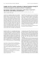
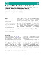
(A) Waterproof encapsulated DRF sensor for retroauricular useFigure 1
(A) Waterproof encapsulated DRF sensor for retroauricular use. (B) The DRF (a) can be used as an additional reference sys-
tem that defines an independent coordinate system in space in addition to the one established by the transmitter unit (b). (C)
The DRF was placed and fixed with tape draping in direct contact with the back of the auricle.
Head & Face Medicine 2006, 2:10 />Page 4 of 16
(page number not for citation purposes)
sule and is connected to the navigation system with a 3 m
long cable. The DRF sensor can either (a) be attached to a
dental splint or (b) be attached retroauricular on the hair-
less skin.
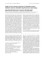
(a) In the oral cavity, the DRF is attached to the upper row
of teeth using a special, removable mouthpiece (Figure 2)
and a 2-component polyether self-hardening material
(Impregum
®
F; ESPE Dental AG, Seefeld, Germany). The
mouthpiece consists of a U-shaped splint which is filled
with a fast-hardening material and applied to the upper
row of teeth exerting slight pressure (about 0.25 atm) at
the centre. The vacuum resulting from hardening of the
material ensures that the mouthpiece is firmly secured in
place in patients with healthy teeth. After the procedure,
the mouthpiece is removed by releasing the vacuum with
a dental hook.
Alternatively, if oral attachment is precluded by the
patient's dental status or for anesthesiological or surgical
reasons, the DRF is attached directly to the scalp, prefera-
bly over the mastoid, behind the auricle.
(b) For retroauricular attachment (Figure 1), the DRF is
placed in the area of the mastoid in such a way that it is in
direct contact with the back of the auricle. The auricle thus
serves as an anatomical barrier against anterior displace-
ment. The retroauricular region is chosen because there is
minimal skin mobility and the auricle provides additional
stability, ensuring stable attachment of the DRF in this
(A) DRF with dental cast for the oral useFigure 2
(A) DRF with dental cast for the oral use. (B) Example of the fixation technique in a skull dummy and (C) in a patient without
rigid head fixation (Type C
1
).
Head & Face Medicine 2006, 2:10 />Page 5 of 16
(page number not for citation purposes)
area. The device was secured in place with 40 mm wide,
skin-friendly tape applied crosswise to the hairless skin
(Figure 1C). To prevent detachment of the tape by contact
with fluids or disinfectants, a waterproof self-adhesive
sterile film was glued over it (Opraflex
®
, Lohmann &
Rauscher Int., Rengsdorf, Germany).
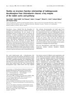
Proper affixation of the DRF was checked in all cases by a
rotation test immediately after image data registration
(Figure 3). To this end, the head was rotated about 120°
from the right lateral to the left lateral position and back
(Figure 3A–C). The spatial coordinates of the fiducial
markers were verified relative to the position of the DRF.
Adequate attachment of the DRF was assumed when the
deviation was < 1 mm in all three spatial direction (carte-
sian x, y, z-coordinates as displayed by the navigation sys-
tem; Figure 3D). If there was greater deviation, the
position was corrected and the attachment optimized
until deviation was within the limit of 1 mm.
Image data acquisition and preparation
Preoperatively, a serial CT or MRI scan was obtained. The
images consisted of a three-dimensional volume data set
of contiguous axial CT or sagittal MR images. In order to
obtain isotropic voxels of 1 mm length one of the follow-
ing CT or MRI protocols was routinely used.
MRI was performed using a T1-weighted 3D GE sequences
(3D MP RAGE) with the parameters: TR 9.7 ms, TE 4 ms,
FA 12°, TI 300 ms, TD 0 s, FOV 256 mm, 256 × 256
matrix, 256 partitions, slice thickness of 1 mm, acquisi-
tion time 11 min 54 s. Alternatively, a high-resolution CT
spiral scan was acquired with 1 mm slice thickness, 512 ×
512 matrix, pitch factor 2, 1 mm increment, and 50–110
(A-C) Proper affixation of the DRF was checked in all cases by a rotation test immediately after image data registrationFigure 3
(A-C) Proper affixation of the DRF was checked in all cases by a rotation test immediately after image data registration. (D)
The spatial coordinates (arrow) of the fiducial markers were verified relative to the position of the DRF.
Head & Face Medicine 2006, 2:10 />Page 6 of 16
(page number not for citation purposes)
mA tube current. The image data were transferred to the
computer workstation in the ACR/NEMA 3.0/DICOM
image data format via a local network (LAN – FTP or
DICOM transfer protocol), or through data media, such as
CD-ROM, magnetic-optical disks (MOD) or magnetic
tape (DAT).
Data processing and preparation was performed using an
autosegmentation technique (ACCISS II software version
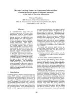
1.9). Image guidance was based on axial planar views
(sagittal, coronal and transaxial), free planar views
(defined by pointer orientation and/or target localiza-
tion), and 3D views of the anatomical objects (skin, skull,
brain surface structures, brain parenchyma and lesion tar-
get) (Figure 4). The image data was registered by means of
point-to-point matching (sequentially sampling 7 two-
component adhesive fiducial markers with a sensor-bear-
ing pointer according to a standardized protocol).
Accuracy measurements
Registration accuracy was determined calculating the fidu-
cial registration error (FRE) expressed as the root mean
square error. The FRE describes the distance between the
position of a marker in the image dataset and the position
measured in the operative field. The mean RMS value is
calculated directly by the navigation system and is dis-
played together with the min. and max. FRE and the Tar-
get Registration Error (TRE – for a certain target point
within the registered volume) on the navigation screen
(Figure 3D).
Image guidance was based on axial planar views (sagittal, coronal and transaxial), free planar views, and 3D views of the ana-tomical objects with tools for targeting and trajectory planningFigure 4
Image guidance was based on axial planar views (sagittal, coronal and transaxial), free planar views, and 3D views of the ana-
tomical objects with tools for targeting and trajectory planning.
Head & Face Medicine 2006, 2:10 />Page 7 of 16
(page number not for citation purposes)
The application accuracy was monitored intraoperatively
using as a reference point a 1 mm burr hole drilled into
the exposed bone margin directly after craniotomy (Figure
5). The initial Cartesian coordinates of this reference
point were determined immediately by means of a
pointer. The measurements were repeated after craniot-
omy immediately before dura opening, three times during
tumour resection (M1–M3) and after closure of the dura,
respectively at the end of the operation. Deviations in x, y,
and z directions were measured as three-dimensional
Position Error (PE in mm) of the reference point relative
to the baseline coordinates of the same point determined
immediately after craniotomy.
Statistical analysis
FRE and PE values are expressed as means +/- standard
deviation from the number (n) of patients in each group.
Data were tested for significance using one-way ANOVA
to determine degree of variability within a group, fol-
lowed by Bonferroni post hoc analysis. Test of pairwise
comparisons were carried out with the Student's t-test to
compare two groups (e.g. for differences in FRE between
the different types of head fixation, as well as for differ-
ences in ∆PE in-/decrease between the different types of
head positioning over the time of surgery). A p < 0.05 was
considered as statistically significant. Data management
and statistical analyses were performed using the SPSS
13.0 for Windows
®
software package.
Results
Patients and indications for frameless stereotaxy
The clinical study included 40 patients with intracerebral
tumours or lesions in the area of the skull base in whom
intraoperative navigation was used to localize the target or
The application accuracy was monitored intraoperatively using as a reference point a 1 mm burr hole (b) drilled into the exposed bone margin (a) directly after craniotomyFigure 5
The application accuracy was monitored intraoperatively using as a reference point a 1 mm burr hole (b) drilled into the
exposed bone margin (a) directly after craniotomy. The Cartesian coordinates of this reference point were used to calculate
the intraoperative Position Error (PE = (∆sagittal
2
+ ∆coronal
2
+ ∆axial
2
)
1/2
) in mm.
Head & Face Medicine 2006, 2:10 />Page 8 of 16
(page number not for citation purposes)
trajectory or to determine the extent of resection. The
patients had the following diagnoses: 2 WHO II gliomas,
8 WHO III gliomas, 7 glioblastomas, 12 metastases, 2 pri-
mary bone tumours, 2 meningiomas, 4 lymphomas, 2
fibrous dysplasia, and one paraganglioma. There were 22
men and 18 women with a mean age of 55.7 years (range
18 – 81 years). CT data sets were used for navigation in 9
cases and MRI data sets in the remaining 31 patients. All
steps of the examinations were approved by the institu-
tional review board. Written informed consent was avail-
able from all patients participating in the study. The
interventions were performed at the Department of Neu-
rosurgery, Charité – Universitätsmedizin Berlin, Campus
Benjamin Franklin.
Clinical application
According to the indication for the use of intraoperative
navigation, the patients were assigned to one of three
types of interventions according to head fixation and use
of the DRF including its mode of attachment (Figure 6).
To assign the patients to one of the three groups, the fol-
lowing questions were answered: „Is it planned to reposi-
tion the patient/the patient's head during the operation?”
and „Is it likely that there will be involuntary head move-
ment during certain surgical manoeuvres?”
Type A comprised 10 patients in whom no intervention-
related repositioning was planned and in whom involun-
tary movement of the head was unlikely because 3-point
Types of intraoperative head fixation with and without DRF dependent on the diagnosis/indication for navigation and the dental statusFigure 6
Types of intraoperative head fixation with and without DRF dependent on the diagnosis/indication for navigation and the dental
status. MLL = Multilocular lesion, SBP = Skull base procedure, BHP = Burr hole procedure, TNA = Transnasal approach, AWC
= Awake craniotomy, NSA = No significant abnormalities, ID = Inadequate dentition, ND = No dentures.
Head & Face Medicine 2006, 2:10 />Page 9 of 16
(page number not for citation purposes)
pin fixation was used. These patients were operated on
with navigation performed under standard conditions
and without additional use of the DRF. The patients of
this group served as controls.
Type B consisted of two subgroups. The first subgroup
included those cases in whom intraoperative reposition-
ing of the head was planned. These were 6 patients sched-
uled for removal of two lesions in one session. All 6
patients were actually repositioned during the operation.
The other 4 patients assigned to this group had large
lesions at the skull base, making it likely that voluntary or
involuntary changes in head position would occur during
the intervention. All 10 patients of this group were oper-
ated on using 3-point pin fixation in combination with a
DRF. The DRF was attached orally (type B1) in 5 cases
(Figure 7) and retroauricularly in the other 5 cases (type
B2).
Type C consisted of those cases in whom intraoperative
head movement was expected or desirable as well as those
patients in whom repositioning might have become nec-
essary in the course of the operation. These were 13
patients scheduled for burr hole procedures for neuroen-
doscopic interventions or biopsy, 3 patients in whom a
transnasal approach was planned, and 4 patients under-
going awake craniotomy for removal of lesions from lan-
guage areas. In 10 patients of this group, the DRF was
attached in the oral cavity (type C1); in the other 10 cases,
retroauricular attachment was necessary because of the
Type B
1
fixation of the headFigure 7
Type B
1
fixation of the head. (A) Patient positioned on the right side for resection of a left frontal metastasis. (B) After repo-
sitioning in the prone position for resection of a left parieto-occipital metastasis. (C) Screenshot of the navigation system
showing the location of the two tumours. 3p = Three point; r.a. = retroauricular.
Head & Face Medicine 2006, 2:10 />Page 10 of 16
(page number not for citation purposes)
dental status or for anesthesiological reasons and in the
patients who underwent awake craniotomy to perform
intraoperative speech testing (type C2).
Registration accuracy
The mean fiducial registration errors (FREs) were 1.51
mm (+/- 0.36 mm SD) in the control group type A (n =
10), 1.56 mm (+/- 0.40 mm SD) in type B1 interventions
(n = 5), 1.54 mm (+/- 0.33 mm SD) in type B2 (n = 5),
1.73 mm (+/- 0.63 mm SD) in type C1 (n = 10), and 1.75
mm (+/- 0.41 mm SD) in type C2 (n = 10) (Figure 8).
There was no statistically significant difference between
rigid pin fixation (r.p.f.) of the head alone (control group:
type A) and r.p.f. with additional DRF (type A vs. type B1;
p > 0.05 and type A vs. type C2, p > 0.05). In DRF-sup-
ported procedures, there was no statistically significant
difference between oral and retroauricular placement of
the DRF, neither in cases with rigid pin fixation (type B1
vs. type B2, p > 0.05), nor in the unfixed head mode (type
C1 vs. type C2, p > 0.05). However, both types of unfixed
head positioning (type C1 and C2) presented with signif-
icant higher FRE mean values compared to control type A
(type A vs. type C1; p < 0.05 and type A vs. type C2; p <
0.05), as well compared to both groups of r.p.f. with addi-
tional DRF (type C1 vs. B1, p < 0.05; type C1 vs. B2, p <
0.05; type C2 vs. type B1, p < 0.05 and type C2 vs. type B2,
p < 0.05).
Application accuracy
The mean position errors (PEs) measured after comple-
tion of craniotomy and before dura opening (on average
71 min after the end of image data registration) were 0.79
Fiducial Registration Error (FRE in mm) in the clinical application with head fixation types A, B1, B2, C1 and C2Figure 8
Fiducial Registration Error (FRE in mm) in the clinical application with head fixation types A, B1, B2, C1 and C2. Data are pre-
sented as mean +/- standard deviation (n = 5 patients in B1 and B2; n = 10 patients in A, C1 and C2). FREs in types C1 and C2
were significantly higher than in control group (type A) (* p < 0,05, t test). There was no statistical difference between the two
B-type (B1 vs. B2) and the two C-type (C1 vs. C2) procedures (n.s. = p > 0.05)
Head & Face Medicine 2006, 2:10 />Page 11 of 16
(page number not for citation purposes)
mm (+/- 0.23 mm SD) in type A interventions, 0.71 mm
(+/- 0.18 mm SD) in type B1, 0.93 mm (+/- 0.34 mm SD)
in type B2, 0.98 mm (+/- 0.31 mm SD) in type C1, and
0.69 mm (+/- 0.25 mm SD) in type C2. The mean PEs
measured at 3 consecutive time points during tumour
resection (M1= about 20 min after dura opening/M2=
about 45 min after dura opening/M3= about 70 min after
dura opening) were 0.95/1.28/1.34 mm in type A, 0.95/
1.17/1.20 mm in type B1, 1.10/1.31/1.44 mm in type B2,
1.19/1.58/1.74 mm in type C1, and 1.03/1.44/1.64 mm
in type C2. The final measurements for determining appli-
cation accuracy at the time of dura closure or at the end of
the intervention (on average 84 min after dura opening)
yielded mean PEs of 1.45 mm (+/- 0.34 mm SD) for type
A interventions, 1.26 mm (+/- 0.29 mm SD) for type B1,
1.44 mm (+/- 0.30 mm SD) for type B2, 1.86 mm (+/-
0.29 mm SD) for type C1, and 1.68 mm (+/- 0.38 mm SD)
for type C2 (Figure 9). ∆PEs (measured as difference in
mm between the initial PE at the time of dura opening
and the corresponding PE at the time of dura closure)
were significantly higher in types C1 and C2 compared
with control group (types A) (* p < 0,05, t test). There were
no statistical differences between the two B-type proce-
dures and control group (type A) (p > 0.05).
Complications
Complications such as damage to the teeth or loosening
resulting from oral attachment of the DRF were not
Mean position errors (PE in mm) in Type A-, B1-, B2-, C1- and C2- interventions measured after completion of craniotomy and before dura opening, at three consecutive time points (M1, M2 and M3) during tumour resection and after dura closure or at the end of the interventionFigure 9
Mean position errors (PE in mm) in Type A-, B1-, B2-, C1- and C2- interventions measured after completion of craniotomy and
before dura opening, at three consecutive time points (M1, M2 and M3) during tumour resection and after dura closure or at
the end of the intervention. ∆PEs (measured as difference in mm between the initial PE at the time of dura opening and the
corresponding PE at the time of dura closure) were significantly higher in types C1 and C2 compared with control group (types
A) (* p < 0,05, t test). There were no statistical differences between the two B-type procedures and control group (type A) (p
> 0.05).
Head & Face Medicine 2006, 2:10 />Page 12 of 16
(page number not for citation purposes)
observed in any of the 15 cases (types B1 and C1). Two
patients showed small pressure sores on the lips due to
direct contact with the plastic coating of the DRF. The
sores healed spontaneously and without complications in
the course of three days.
Retroauricular DRF attachment was also not associated
with any major complications. None of the 15 patients in
this group developed any pressure sores in the area of the
auricle or the skin over the mastoid (types B2 and C2).
The waterproof self-adhesive film prevented detachment
of the tape, e.g. by disinfectant, in all 15 cases. One patient
developed an allergic skin reaction to the tape used. The
irritated skin responded well to topical ointment applica-
tion and the irritation resolved within 24 hours.
Discussion
Neuronavigation systems for frameless stereotaxy have
been used in cranial neurosurgery since the middle of the
1980s [1,2]. Owing to the rapid technological develop-
ment in the field of image processing and in computer
technology, such navigation systems are now used rou-
tinely. They are helpful not only in intraoperative anatom-
ical orientation, but also in delimitation of healthy from
pathological processes and in achieving accurate align-
ment of instruments at the operation site. Although com-
puter- and image-guided surgical procedures are an
improvement of frame-guided stereotaxy, most naviga-
tion systems for frameless stereotaxy still require rigid fix-
ation of the patient's head throughout the operation.
As with the referencing methods of other standard naviga-
tion systems [4,5], any change in the relative positions of
the head and the transmitter used for reference leads to a
loss of alignment between the virtual and the actual coor-
dinate system in electromagnetic systems as well. Thus, a
change in head position upon completion of image data
registration precludes navigation unless the registration
procedure is repeated. For these reasons, a second refer-
ence system is required that is attached directly to the tar-
get object in order to track all movements in relation to
the primary coordinate system in those situations where
movement cannot be excluded or rigid pin fixation of the
patient is not desirable.
Frameless stereotaxy without rigid-pin fixation of the head
Various techniques for identifying and compensating for
intraoperative head movements during image-guided sur-
gery have been published to date [12-18]. Ohhashi et al.
[17], for example, reported on their experience with an
electromagnetic navigation system originally developed
for complex ENT operations of the sinus. This system
comprises a plastic headset and does not require rigid
head fixation. An advantage of this system described by its
users is the fact that the headset simultaneously serves as
a reference for automated image registration without the
need for placement of fiducial markers. However, this sys-
tem is geometrically restricted to the frontal region and
the facial skull, ensuring an adequate navigational accu-
racy only in a limited volume around the headset, i.e. the
area of the midface and the sinus. In contrast, the sensor-
based DRF presented in this study enabled image data reg-
istration over the entire geometric area of the head where
markers are placed. This is especially significant for intrac-
ranial operations as the number and size of the clusters
registered directly affects the surgical accuracy in the
respective area [9-11].
Another, really non-invasive attachment technique for a
reference system, the so-called Vogele-Bale-Hohner
mouthpiece, which moves with the patient's head was
described by Bale and co-workers [18] in 2000. It acts as a
reference arc that is attached to a tailored vacuum-affixed
dental cast. The authors demonstrated that the accuracy
achieved with their system is comparable to that of rigid
pin fixation [18]. However, the size and shape of the ref-
erence frame that is also used for registration and the reli-
ance on optical measurement also has drawbacks in that
patient comfort is restricted and the system is of limited
usefulness when the patient is positioned prone and the
system thus comes to lie on the side away from the cam-
era. Moreover, the device cannot be used in awake crani-
otomy with intraoperative language mapping since the
mouthpiece does not allow the patient to speak. This
problem can be overcome by the use of the sensor-based
DRF and its positioning in the retroauricular area. Moreo-
ver, an electromagnetic system avoids the line-of-sight
problem, i.e. it does not require an undisturbed visual
contact between the DRF and a camera system. The here
described electromagnetic technique thus allows unre-
stricted positioning as well as intraoperative repositioning
of the patient. As the position of the sensor-bearing
pointer is determined relative to the coordinate system
defined by the DRF, the system operates in a virtual envi-
ronment. Head movements and changes in position can
be directly followed on the system's monitor in real-time.
The same also holds true for image-guided instrument
control. Here, very minute changes in position can
directly affect the identification e.g. of a trajectory chosen
on the basis of the image data.
Accuracy of frameless stereotaxy with the DRF in the
clinical application
The overall precision of the DRF in clinical use is affected
by various factors. These include (a) the accuracy of the
image data set employed, (b) various possibilities of error
in the registration of the image data, (c) external effects on
the positional accuracy, and (d) the technical accuracy of
the pulsed DC magnetic measurement technique used:
Head & Face Medicine 2006, 2:10 />Page 13 of 16
(page number not for citation purposes)
(a) Both the voxel size and geometrical distortions in
imaging (CT and MRI) have a direct effect on the accuracy
of the 3D image data set. The maximum deviation that is
possible corresponds to the extent of a voxel and thus cru-
cially depends on the layer thickness of the tomographic
technique used. This source of error is independent from
the physical principle of the navigation technique.
(b) Various errors can be calculated as a measure for the
quality of the image data registration. This is intended to
enable comparisons between different navigation sys-
tems. In recent years, the nomenclature for analysis of
measurement errors suggested by Fitzpatrick, Maurer and
West [9,10] has become widely accepted. Usually, the
fiducial registration error (FRE) is defined as a value for
Table 1: Clinical data of 40 cases
Patient No. appl. type & procedure gender & age diagnosis localization CT/MRI-data FRE (mm)
1 A m 28 y glioma WHO III left frontal MRI 1,74
2 A f 72 y glioblastoma left frontal MRI 1,17
3 A f 52 y metastasis right occipital MRI 1,28
4 A f 68 y glioma WHO III right parietal MRI 2,16
5 A f 81 y glioblastoma left parietal MRI 1,57
6 A f 56 y metastasis left temporal MRI 1,65
7 A f 73 y metastasis right frontal MRI 1,36
8 A m 30 y metastasis left temporal MRI 0,91
9 A m 61 y glioblastoma left parietal MRI 1,37
10 A m 60 y glioblastoma left parietal MRI 1,84
11 B
1
(MLL) f 63 y metastasis left frontal/left parietal MRI 2,11
12 B
1
(MLL) m 63 y metastasis right frontal/left temporal MRI 1,24
13 B
1
(MLL) f 48 y metastasis left frontal/right frontal MRI 1,85
14 B
1
(MLL) f 66 y metastasis left frontal/left occipital MRI 1,44
15 B
1
(SBP) m 49 y prim. bone tumour skull base + orbita CT 1,17
16 B
2
(MLL) f 67 y metastasis right frontal/right parietal MRI 1,41
17 B
2
(MLL) f 68 y metastasis right frontal/right parietal MRI 1,33
18 B
2
(SBP) m 54 y meningioma skull base + orbita CT 1,24
19 B
2
(SBP) f 52 y meningioma skull base + orbita CT 1,68
20 B
2
(SBP) m 67 y prim. bone tumour skull base + orbita CT 2,05
21 C
1
(BHP) f 18 y astrocytoma WHO II left temporal MRI 2,54
22 C
1
(BHP) m 56 y astrocytoma WHO III left temporal MRI 1,87
23 C
1
(BHP) m 27 y lymphoma right parietal MRI 1,57
24 C
1
(BHP) m 61 y glioblastoma left frontal CT 1,21
25 C
1
(BHP) m 64 y lymphoma left temporal MRI 1,17
26 C
1
(BHP) m 46 y lymphoma right temporal MRI 1,30
27 C
1
(BHP) m 65 y glioma WHO III left temporal MRI 2,98
28 C
1
(TNA) m 35 y fibrous dysplasia skull base CT 1,32
29 C
1
(TNA) f 62 y paraganglioma right Fossa pterygopalatina MRI 2.12
30 C
1
(TNA) m 54 y fibrous dysplasia skull base CT 1,24
31 C
2
(BHP) m 64 y lymphoma left frontal CT 1,33
32 C
2
(BHP) f 51 y glioblastoma left frontal MRI 1,54
33 C
2
(BHP) m 54 y astrocytoma WHO III right frontal MRI 1,87
34 C
2
(BHP) m 48 y astrocytoma WHO II left frontal MRI 2,27
35 C
2
(BHP) m 65 y metastasis left frontal CT 2,24
36 C
2
(BHP) f 70 y glioblastoma left temporal MRI 1,56
37 C
2
(AWC) f 66 y metastasis left frontal MRI 1,08
38 C
2
(AWC) m 26 y glioma WHO III left fronto-temporal MRI 1,87
39 C
2
(AWC) f 63 y glioma WHO III left temporal MRI 2,23
40 C
2
(AWC) m 56 y glioma WHO III left temporal MRI 1,51
m = male; f = female; y = years; FRE = Fiducial Registration Error
Type A (control group) = 3-point-pin fixation; no DRF
Type B
1
= 3-point-pin fixation; oral DRF; Type B
2
= 3-point-pin fixation; retroauricular DRF
Type C
1
= unfixed head; oral DRF; Type C
2
= unfixed head; retroauricular DRF
MLL = multilocular lesion; BHP = burr hole procedure for biopsy/endoscopy; SBP = Skull base procedure; TNA = transnasal approach; AWC =
awake craniotomy
Head & Face Medicine 2006, 2:10 />Page 14 of 16
(page number not for citation purposes)
the measurement accuracy of image data registration. The
FRE describes the distance between the position of a fidu-
cial localized in the image data and the position measured
in the operation site and transformed into the image coor-
dinate system by means of the registration image. Impor-
tant factors are the error in the positional measurement
system used in determining the position in the operation
site and the accuracy of the localization of the fiducial
positions in the image data set. Statistical analysis of the
FRE measurements in the patients of our study shows that
there are no significant differences in mean registration
accuracies between rigid 3-point pin fixation with (types
B1 and B2) and without (type A) use of a DRF. This result
suggests that there is no immediate benefit from the use of
an additional DRF in terms of accuracy of image data reg-
istration. The registration accuracies in patients without
rigid fixation of the head (types C1 and C2) did not differ
significantly between oral and retroauricular attachment
of the DRF. However, FRE values for types C1 and C2 were
significantly higher (on average 10–15%) than in patients
with rigid pin fixation. This may be caused by inadvertent
micro movements of the Fiducial positions during the reg-
istration procedure, e.g. due to the effect of respiration on
the unfixed head. Nevertheless, also C1 and C2 type val-
ues seem to be in an acceptable range for microneurosur-
gical procedures (means: C1 = 1.73 mm +/-SD; C2 = 1.75
mm +/- SD) as they compare well with those achieved
with other standard navigation techniques since most
commercial navigation systems assume registration to be
successful if the FRE is less than 3 mm.
In order to detect a fall in application accuracy, e.g. due to
displacement of the DRF, at an early stage and to be able
to act on it, a fixed landmark can be checked at defined
times over the entire period of the operation. As such a
landmark, which is virtually undisplaceable, a burr hole
near the craniotomy was chosen. To quantify this measure
the so-called Position Error (PE) can be assessed. The PE
describes the extent to which the accuracy of point locali-
zation changes between two or more time points in the
course of the operation. The results listed in Figure 9 show
that measuring accuracy in general decreases with the
length of the operation. This is due to various factors such
as the actual number of head movements having occurred
at the time of measurement and physiological factors such
as changes in skin turgor in the retroauricular cases. Addi-
tionally, the angle at which the stylus is held when pin-
pointing the 1 mm burr hole has a significant impact on
measurement accuracy in the submillimeter range. This
may explain the apparent improvement of the PE between
two measurements in some of the cases. In general, our
results demonstrate that the additional use of a DRF in
combination with pin fixation of the head (types B1 and
B2) has an application accuracy averaged over time which
is comparable to that achieved with permanent rigid head
fixation (control group: type A), even when head position
is changed intraoperatively. Intraoperative changes in
position are thus fully compensated for by use of the DRF.
The fact that the lowest ∆PEs were obtained for type B2
interventions as compared with type A suggests that in
type B2 operations even inadvertent displacement of the
pin fixation has been compensated for. The significantly
higher ∆PE values obtained in the group of patients oper-
ated on without rigid head fixation (types C1 and C2) are
most likely attributable to a wider range of detectable
movements, resulting in a higher degree of deterioration
in the application accuracy over the time of surgery. How-
ever, mean ∆PE values for C-type procedures did not
exceed 1 mm and over all PEs were less than 2 mm. The
authors believe, that this makes intraoperative head track-
ing by DRF a suitable alternative to conventional rigid
head fixation for certain indications, such as burr hole
procedures, transnasal/transsphenoidal approaches and
awake craniotomies. Oral attachment of the DRF was
found to be superior to retroauricular attachment in com-
bination with both types of head positioning (B:fixed and
C:unfixed). Retroauricular attachment should therefore
be reserved to those patients in whom oral fixation is not
possible.
(c) Another critical issue is the potential interference of
nearby conductive metals with the electromagnetic meas-
uring technique. The susceptibility to such external distor-
tion can be markedly reduced by using a DC technique
instead of an AC technique [8]. The measuring accuracy of
DC probes is nearly completely unaffected by most of the
instruments of a neurosurgical standard set. Nevertheless,
interferences occurs, for instance with the equipment used
for intraoperative electrophysiological testing. This is why
care must be taken when using the setup described here
not to inadvertently induce an electrical field by perform-
ing electrical stimulation while the position of the cortical
stimulation site is being determined by the navigation sys-
tem. Due to the electromagnetic principle, the reference
sensor may not be used with intraoperative MRI as well.
(d) The system accuracy of the electromagnetic navigation
technique is essentially determined by the physical func-
tion principle as well as the hardware and software com-
ponents implementing this principle. For the
electromagnetic localizing sensor embedded in the DRF
this is expressed technically by the term "static accuracy",
i.e. by how accurately the position and the orientation of
a sensor in space can be determined. The static accuracy
(1.8 mm RMS – position and 0.5° RMS – orientation as
specified by the manufacturer) is defined as root mean
squared deviation of a true measurement of the magnetic
centre of a single sensor with respect to the magnetic cen-
tre of a single transmitter measured over the translation
range. Accuracy varies from one location to another over
Head & Face Medicine 2006, 2:10 />Page 15 of 16
(page number not for citation purposes)
the translation range and will be degraded if there are
interfering electromagnetic noise sources or metal in the
operating environment.
Fixation and attachment technique
The use of a dental splint attached to the upper row of
teeth appears to be feasible in patients with healthy teeth.
The self-hardening material used here is non-toxic,
hypoallergic, fast-drying, and form-stable. Firm attach-
ment is ensured as long as a vacuum is maintained
between the hardened 2-component polyether system
and the dental surface. Once the vacuum is released, e.g.
with a small dental hook, the splint can be removed easily
and rapidly. Others have described the ease of using such
material intraoperatively. For example, Bale et al.
[15,16,18] used a comparable polyether material for
attachment of the mouthpiece of the Vogele-Bale-Hohner
head holder. After two of our patients developed pressure
sores on the lips, we have since placed a wet compress
around the DRF following its placement. The compress
protects the oral soft tissue and additionally prevents dry-
ing of the oral mucosa. No pressure sores have occurred
thereafter.
Retroauricular attachment with adhesive tape was found
to be inferior to oral attachment in terms of application
accuracy, which is probably due to displacement of the
DRF on the skin although no loosening of the tape was
noted in any of the patients. Nevertheless, we think that a
decrease in skin turgor and the weight of the sterile film
are potential causes of the inaccuracies measured. With
this potential source of inaccuracy in mind, one can still
use retroauricular attachment of the DRF with benefit in
patients with a poor dental status and in patients sched-
uled for awake craniotomy, as in patients undergoing
awake craniotomy, pain associated with placement of the
pins [20] and the risk of injuries through inadvertent head
movements, less patient comfort, and declining ability of
the awake patient to cooperate as the operation proceeds
interfere with rigid fixation of the head.
Conclusion
Rigid pin fixation of the head for microneurosurgical pro-
cedures in combination with frameless stereotaxy has to
be considered gold standard, since highest accuracy is
achieved only with intraoperative immobilization of the
patient's head. However, based on the experience gained
with intraoperative motion tracking, the authors see a
high clinical potential for DRF application in cranial nav-
igation. The use of an additional reference sensor
increases the application scope of image-guided naviga-
tion procedures to include, for example, any bioptic or
endoscopic intervention, in which rigid pin fixation of the
cranium is not required or desired. The system allows
highly flexible variation of the surgical strategy including
intraoperative repositioning of the patient without
impairment of navigational accuracy. In awake craniot-
omy patient comfort is improved by the fact that rigid pin
fixation of the head is no longer required. For all other
procedures, continuous tracking of head motion ensures
automatic correction of spatial distortion with mechani-
cal alteration of the head position. With a special dental
cast for the oral attachment and the alternative option of
a non-invasive retroauricular attachment, flexibility in the
clinical use of the DRF is ensured.
Abbreviations
AWC – Awake craniotomy
BHP – Burr hole procedure
CT – Computed tomography
DC – Direct current
DRF – Dynamic reference frame
FRE – Fiducial registration error
ID – Inadequate dentition
MLL – Multilocular lesion
MRI – Magnetic resonance imaging
ND – No dentures
NSA – No significant abnormalities
PE – Position error
r.a. – retroauricular
r.p.f. – rigid pin fixation
SBP – Skull base procedure
TNA – Transnasal approach
Competing interests
The author(s) declare that they have no competing inter-
ests.
Authors' contributions
OS – has defined conception and study design. He was
responsible for collecting, analyzing and interpreting the
data.
SS, SM, BK, SH, RS & TP – have made substantial contri-
butions in collecting, analyzing and interpreting the data
Publish with BioMed Central and every
scientist can read your work free of charge
"BioMed Central will be the most significant development for
disseminating the results of biomedical research in our lifetime."
Sir Paul Nurse, Cancer Research UK
Your research papers will be:
available free of charge to the entire biomedical community
peer reviewed and published immediately upon acceptance
cited in PubMed and archived on PubMed Central
yours — you keep the copyright
Submit your manuscript here:
/>BioMedcentral
Head & Face Medicine 2006, 2:10 />Page 16 of 16
(page number not for citation purposes)
and have been involved in revising the manuscript criti-
cally for important intellectual content.
MB – has revised the manuscript critically for important
intellectual content.
TK – has been involved in collecting and interpreting the
data. He has revised the manuscript critically for impor-
tant intellectual content and has given final approval of
the manuscript to be published.
Acknowledgements
The authors thank Dr. Sven Schönherr and Mr. Udo Warschewske
(Schaerer Mayfield Technologies GmbH, Germany) for their technical sup-
port and their assistance in the implementation of this study. The author's
research on sensor-based neuronavigation is supported by a "Forschungs-
foerderung" grant from Charité-Universitaetsmedizin Berlin (Projects No.
2004-703 & 2006-725).
References
1. Roberts DW, Strohbein JW, Hatch JF, Murray W, Kettenberger H: A
frameless stereotactic integration of computerized tomo-
graphic imaging and the operating microscope. J Neurosurg
1986, 65:545-549.
2. Watanabe E, Mayanagi Y, Kosugi Y, Manaka S, Takakura K: Open
surgery assisted by the Navigator, a stereotactic articulated,
sensitive arm. Neurosurgery 1991, 28:792-800.
3. Golfinos JG, Fitzpatrick BC, Smith LR, Spetzler RF: Clinical use of a
frameless stereotactic arm: results of 325 cases. J Neurosurg
1995, 83:197-205.
4. Gumprecht HK, Widenka DC, Lumenta CB: BrainLab VectorVi-
sion Neuronavigation System: Technology and clinical expe-
riences in 131 cases. Neurosurgery 1999, 44:97-105.
5. Roessler K, Ungersboeck K, Dietrich W, Aichholzer M, Hittmeir K,
Matula C, Czech T, Koos WT: Frameless stereotactic guided
neurosurgery: Clinical experiences with an infrared based
pointer device navigation system. Acta Neurochir (Wien) 1997,
139:551-559.
6. Koivukangas J, Louhisalmi Y, Alakuijala J, Oikarinen J: Ultrasound-
controlled neuronavigator-guided brain surgery. J Neurosurg
1993, 79:36-42.
7. Suess O, Kombos Th, Kurth R, Suess S, Mularski S, Hammersen S,
Brock M: Intracranial image-guided neurosurgery: Experi-
ence with a new electromagnetic navigation system. Acta
Neurochir (Wien) 2001, 143:927-934.
8. Zaaroor M, Bejerano Y, Weinfeld Z, Ben-Haim S: Novel magnetic
technology for intraoperative intracranial frameless naviga-
tion: in vivo and in vitro results. Neurosurgery 2001,
48:1100-1108.
9. Fitzpatrick JM, West JB, Maurer CR: Predicting error in rigid-
body, point-based registration. IEEE Transactions on Medical Imag-
ing 1998, 17:694-702.
10. Fitzpatrick JM, West JB: The distribution of target registration
error in rigid-body, point-based registration. IEEE Transactions
on Medical Imaging 2001, 20:917-927.
11. West JB, Fitzpatrick JM, Toms SA, Maurer CR, Maciunas RJ: Fiducial
point placement and the accuracy of point based, rigid body
registration. Neurosurgery 2001, 48:810-816.
12. Ryan MJ, Erickson RK, Levin DN, Pelizzari CA, Macdonald RL, Dohr-
mann GJ: Frameless stereotaxy with real-time tracking of
patient head movement and retrospective patient-image
registration. J Neurosurg 1996, 85:287-292.
13. Leuthardt EC, Fox D, Ojemann GA, Dacey RG, Grubb RL, Rich KM,
Ojemann JG: Frameless stereotaxy without rigid pin fixation
during awake craniotomies. Stereotact Funct Neurosurg 2002,
79:256-61.
14. Takeuchi H, Yoshida M, Kubota T, Ishii H, Sato K, Handa Y, Itoh H:
Frameless stereotactic radiosurgery with mobile CT, mask
immobilization and micro-multileaf collimators. Minim Inva-
sive Neurosurg 2003, 46:82-85.
15. Bale RJ, Vogele M, Freysinger W, Gunkel AR, Martin A, Bumm K,
Thumfart WF: Minimally invasive head holder to improve the
performance of frameless stereotactic surgery. Laryngoscope
1997, 107:373-377.
16. Bale RJ, Vogele M, Martin A, Auer T, Hensler E, Eichberger P, Freys-
inger W, Sweeney R, Gunkel AR, Lukas PH: VBH head holder to
improve frameless stereotactic brachytherapy of cranial
tumors. Comput Aided Surg 1997, 2:286-291.
17. Ohhashi G, Kamio M, Abe T, Otori N, Haruna S: Endoscopic tran-
snasal approach to the pituitary lesions using a navigation
system (InstaTrak system): technical note. Minim Invasive Neu-
rosurg 2002, 45:120-123.
18. Bale RJ, Burtscher J, Eisner W, Obwegeser AA, Riegr M, Sweeney RA,
Dessl A, Giacomuzzi SM, Twerdy K, Jaschke W: Computer
assisted neurosurgery by using a noninvasive vacuum-affixed
dental cast that acts as a reference base: another step
towards a unified approach in the treatment of brain
tumors. J Neurosurg 2000, 93:208-213.
19. Suess O, Schönherr S, Schilling A, Kühn B, Mularski SO, Suess S,
Brock M, Kombos Th: [Sensor-based detection of skull posi-
tioning for image-guided cranial navigation under free head
mobility]. Rofo 2005, 177:1000-1008.
20. Danks RA, Rogers M, Aglio LS, Gugino LD, Black PM: Patient toler-
ance of craniotomy performed with the patient under local
anesthesia and monitored conscious sedation. Neurosurgery
1998, 42:28-34.