Refrigeration and Air Conditioning 3 E Part 5 ppt
Bạn đang xem bản rút gọn của tài liệu. Xem và tải ngay bản đầy đủ của tài liệu tại đây (181.11 KB, 30 trang )
114
Refrigeration and Air-Conditioning
A safer circuit injects the discharge gas directly after the expansion
valve or into the evaporator outlet and before the sensor of the
expansion valve. With this arrangement, the expansion valve will
admit extra refrigerant, and gas entering the compressor will be
normally cool. These control methods are wasteful of energy.
9.12 Relief valves
Under several possible conditions of malfunction, high pressures
can occur in parts of the system and mechanical relief devices are
advised or mandatory. The standard form of relief valve is a spring-
loaded plunger valve. No shut-off valve is permitted between the
relief valve and the vessel it protects, unless two such valves are
fitted, when the shut-off may isolate one at a time [13]. Two valves
are required on a vessel greater than 285 litres in volume.
In all cases, the outlet of the valve must be led to the open air, in
a location where the sudden discharge of refrigerant will not cause
annoyance or danger. Under certain circumstances, a relief valve
from the high-pressure side may enter the low side of the same
system. Small vessels may have a plug of a low melting point metal,
which will melt and release the pressure in the event of fire. Plunger-
type relief valves, if located outdoors, should be protected from the
ingress of rain, which may corrode the seat. Steel valves, when
installed, should have a little oil poured in to cover the seat as rust
protection.
To prevent overpressure within a compressor, a relief valve or
bursting disc is often fitted between the inlet and discharge
connections.
Evaporator
Compressor
Capacity reducing
regulator
(constant pressure)
Condenser
Thermostatic
liquid
injection valve
Expansion
valve
Figure 9.7
Capacity reduction by hot gas injection, with compensating
liquid injection
Controls and other circuit components
115
9.13 Shut-off valves
Manual stop valves are required throughout a circuit to permit
isolation during partial operation, service or maintenance (see Figure
9.8).
Figure 9.8
Seal cap shut-off valve
Small valves which are to be operated frequently have a packless
gland, either a diaphragm or bellows, and a handwheel.
Valves of all sizes which are only used occasionally will be sealed
with ‘O’ rings. As a safeguard against leakage, they have no handwheel
fitted and the stem is provided with a covering cap which is only
removed when the valve is to be operated. The stem will have flats
for operation by a spanner. Most such valves can be back-seated to
permit changing the ‘O’ rings.
116
Refrigeration and Air-Conditioning
Valves should not be installed with the stem downwards, as any
internal dirt will fall into the spindle thread.
Under low-temperature conditions, ice will form on the spindle
and will be forced into the gland if the valve is operated quickly.
Under such circumstances, the spindle should be well greased, or
the ice melted off first.
Service stop valves on small compressors may also carry a
connection for a pressure cut-out or gauge, or for the temporary
fitting of guages or charging lines when servicing. The valve back-
seats to close off this port while gauges are being fitted. Valve seats
are commonly of soft metal or of a resistant plastic such as PTFE.
9.14 Strainers
Piping circuits will usually contain a small quantity of dirt, scale and
swarf, no matter what care is taken to keep these out. A strainer is
fitted in the compressor suction to trap such particles before they
can enter the machine. Such strainers are of metal mesh and will be
located where they can be removed for cleaning. In some con-
figurations two strainers may be fitted.
As an extra safeguard, on new compressors a fabric liner may be
fitted inside the mesh strainer to catch fine dirt which will be present.
Such liners must be removed at the end of the running-in period,
as they create a high resistance to gas flow.
Oil strainers may be of metal mesh and within the sump, in which
case the sump must be opened for cleaning. Self-cleaning disc strainers
are also used, the dirt falling into a drain pot or into the sump itself.
There is an increasing tendency to provide replaceable fabric oil
filters external to the compressor body, following automobile practice.
9.15 Strainer-driers
With the halocarbons, it is essential to reduce the water content of
the refrigerant circuit to a minimum by careful drying of components
and the fitting of drying agents in the system. The common form of
drier is a capsule charged with a solid desiccant such as silica gel,
activated alumina or zeolite (molecular sieve), and located in the
liquid line ahead of the expansion valve. These capsules must have
strainers to prevent loss of the drying agent into the circuit, and so
form an effective strainer-drier to also protect the valve orifice from
damage by fine debris.
Large driers are made so they can be opened, and the spent
drying agent removed and replaced with new. Small sizes are
throwaway. Driers may also be used in the suction line.
Controls and other circuit components
117
9.16 Sight glasses
Pipeline sight glasses can be used to indicate whether gas is present
in a pipe which sould be carrying only liquid. The main application
in refrigeration is in the liquid line from the receiver to the expansion
valve. If the equipment is running correctly, only liquid will be
present and any gas bubbles seen will indicate a refrigerant shortage
(see also Chapters 11 and 33).
Sight glasses for the halocarbons are commonly made of brass,
and may have solder or flare connections. For ammonia, they are
made of steel or cast iron.
Since the interior of the system can be seen at this point, advantage
is taken in most types to insert a moisture-sensitive chemical which
will indicate an excess of water by a change of colour. When such an
indication is seen, the drier needs changing or recharging, and the
colour should then revert to the ‘dry’ shade.
9.17 Charging connection
In order to admit the initial refrigerant charge into the circuit, or
add further if required, a charging connection is required. The
safest place to introduce refrigerant will be ahead of the expansion
valve, which can then control the flow and prevent liquid reaching
the compressor. The usual position is in a branch of the liquid line,
and it is fitted with a shut-off valve and a suitable connector with a
sealing cap or flange. A valve is needed in the main liquid line, just
upstream from the branch and within reach. For the method of
use, see Chapter 11.
The relative positions of all these components are shown in the
complete circuit in Figure 9.9.
9.18 Auxiliary components
More complex refrigeration systems may have components for specific
purposes which are not encountered in simple circuits. Non-return
or check [24] valves will be found in the following positions:
1. On heat pump circuits, to prevent flow through expansion valves
which are not in service on one cycle
2. On hot gas circuits, to prevent the gas entering another evaporator
3. Where several compressors discharge into one condenser, to
prevent liquid condensing back to an idle compressor
4. Where two or more evaporators work at different pressures, to
prevent suction gas flowing back to the colder ones
118
Refrigeration and Air-Conditioning
9.19 Liquid refrigerant pumps
In a flooded evaporator, the movement of the liquid may be sluggish,
with resulting low heat transfer. Liquid pumps can be used to circulate
refrigerant from the suction separator (or ‘surge drum’), through
the evaporator(s) and back. In the separator, remaining liquid falls
back and is recirculated, while vapour goes to the compressor (see
Figure 9.10). These pumps are found mainly on low-temperature
coldrooms, blast freezers and process applications [25].
High-pressure
cut-out
Evaporator
Oil pressure
safety switch
Oil pressure
gauge
Compressor
Expansion
valve
Low-pressure
cut-out
Equalizer
Phial
Suction
stop valve
Suction
pressure
gauge
Discharge
pressure
gauge
Sight
glass
Charging
connection
Solenoid
valve
Strainer
drier
Valve
Receiver
outlet
valve
Receiver
Relief
Level
gauge
Discharge
stop valve
Condenser
Water
Condensing
pressure control
Figure 9.9
Dry expansion circuit showing components
Suction
Liquid
Low-pressure
accumulator
–separator
Evaporator
1
Evaporator
2
Evaporator
3
Wet return/suction
Slope
Liquid
refrigerant
pump
Pumped liquid supply main
Figure 9.10
Pumped liquid circuit
9.20 Suction separators
Suction line accumulators are sometimes inserted in halocarbon circuits,
to serve the same purpose of separating return liquid and prevent
it passing over to the compressor. Since this liquid will be carrying
Controls and other circuit components
119
oil, and this oil must be returned to the compressor, the outlet pipe
within the separator dips to the bottom of this vessel and has a small
bleed hole, to suck the oil out (see Figure 9.11).
Suction traps are now widely used, particularly on rolling piston
and scroll compressors, to prevent liquid passing into the compressor.
9.21 Liquid separators
Separation vessels can be inserted in a liquid line. Liquid will fall to
the bottom and pass through an expansion device to an evaporator.
High pressure gas will rise to the top of the vessel and can then be
used for heating or for hot gas defrost of another heat exchanger.
9.22 Overheat protection
Small compressors will have motor overheat protection adjacent to
the hermetic shell or built into the winding (see Section 4.8) and
larger motors will have contactor–starters with overcurrent devices.
Overheat protection is also fitted on many machines, to guard against
high motor winding, cylinder head or oil temperatures. These usually
take the form of thermistor detectors, connected to stop the motor.
Accumulator
body
Oil return
bleed hole
Figure 9.11
Suction line accumulator or liquid trap
120
Refrigeration and Air-Conditioning
9.23 Integrated control systems
The purpose of the various electromechanical elements of a circuit
is to effect monitoring, safety and automatic control, and these may
be connected separately into a custom-built system. The availability
of electronic logic circuits gives the possibility of integrated systems
and superior control, using a large number of input signals. Observed
parameters are:
Electrical supply
Load temperature
Air and water flows
Number of compressors running, and loading stages
Condenser pressure
Number of condensers running
Condenser fan speed
Evaporator temperature
Discharge temperature
Cylinder head temperature
Motor current
Expansion valve opening
Refrigerant shortage
Control may then be effected of:
Number and stages of compressors running
Limitation of motor start frequency
Limitation of maximum electrical demand
Number of fans or condensers running
Fan speeds
Number of fans or evaporators running
Warning of faulty plant
Shutting down faulty plant
Starting standby plant
Monitoring energy used
Printed running logs
Scheduling maintenance
Remote alarm systems
Integrated control systems are mainly found on factory-assembled
equipment, but the increased use of programmable logic controllers
for process control is giving designers and installation mechanics
the experience to apply these methods to custom-built refrigeration
systems [26].
10 Selection and balancing of
components
10.1 Balanced system design
The four main components of a vapour compression refrigeration
circuit – the evaporator, the compressor, the condenser and the
expansion valve – must be selected to give a balanced system.
Each of these items must:
1. Be suitable for the application
2. Be correctly sized for the duty
3. Function as required in conjunction with the other components
The system designer must consider these components and examine
the options which may be available in order to determine a best
selection with reference to first cost, installation, operation, running
cost, maintenance and expected life. The following factors are some
of those affecting the final decision:
1. If the initial capital cost is the deciding factor, then the plant
will almost certainly be more expensive to operate.
2. Installation of a new plant may cause serious disruption of the
user’s ongoing business, and the extent of this disruption should
be determined before it is too late. Apart from the installation
of the plant itself, there is the associated builders’ work and the
temporary disconnection of other services. The use of factory-
built packaged equipment helps to reduce this nuisance.
3. Most systems are now automatic in operation, but the user’s
staff must be aware of the control system and have facilities to
run on manual control, as far as this may be possible, in the
event of a control failure.
4. Operators must understand the function of the system. If not,
they will not have the confidence to work on or with it, and the
122
Refrigeration and Air-Conditioning
plant will not be operated at its best efficiency. Also, if it breaks
down for any reason, they will be unable to put it right.
5. The cost of electricity, other fuels, water, spare parts and operating
and maintenance labour represents the greater part of the owning
costs of a refrigeration system. It is probable that a small extra
expenditure on some items, especially heat exchangers, will
reduce running costs.
6. A lot of modern equipment is almost maintenance-free but the
user must be aware of what maintenance functions are required,
whether these are within the scope of his own staff and where to
get assistance. Where maintenance is contracted out, it is
important that this should be carried out, at least for the warranty
period, by the supplier.
7. Life expectancies are 15–20 years for refrigeration systems, and
somewhat less for small packaged equipment. Where the need
is for a shorter period, such as a limited production run or for
a temporary building, equipment of lower quality or second-
hand plant could be considered.
10.2 Evaporating temperature
The next step is to decide a suitable evaporating temperature. This
will be set by the required load condition and the appropriate
temperature differential (∆T) across the evaporator. In the context
of evaporator selection, the ∆T used is the difference between the
evaporating refrigerant and the temperature of the fluid entering
the cooler, not the log mean temperature difference (see [1–5]).
In systems where the evaporator cools air, the air itself becomes
the heat transfer medium and its temperature and humidity must
be considered in relation to the end product. Where the product
cannot suffer dehydration, the ∆T may be high, so as to reduce the
size and cost of the coil, but the lower the evaporating temperature
falls, the lower will be the capacity of the compressor and its COP.
In these circumstances, a first estimate might be taken with a ∆T of
10–12 K and cross-checked with alternative plant either side of this
range. In each case, the ‘owning’ cost, i.e. taking into account the
running costs, should be considered by the user. For a cold store
example, running 8760 hours per year, see Table 10.1.
Unsealed products will be affected by low humidity of the air in
the cooled space and may suffer dehydration. Conversely, some
food products such as fresh meat will deteriorate in high humidities.
Since the dew point of the air approaches the fin surface temperature
of the evaporator (see also Chapter 24), the inside humidity is a
function of the coil ∆T. That is to say, the colder the fin surface, the
Selection and balancing of components
123
more moisture it will condense out of the air, and the lower will be
the humidity within the space. Optimum conditions for all products
likely to be stored in cooled atmospheres will be found in the standard
reference books, or may be known from trade practice. The following
may be taken as a guide:
Products that dehydrate quickly, such as
most fruits and vegetables ∆T = 4 K
Products requiring about 85% saturated air ∆T = 6 K
Products requiring 80% saturation or drier ∆T = 8 K
Materials not sensitive to dehydration ∆T = 10 K upwards
A further consideration may be the possibility of reducing ice build-
up on the evaporator, whether this is in the form of frost on fins or
ice on the coils of a liquid chilling coil. Where temperatures close
to freezing point are required, it may be an advantage to design
with an evaporator temperature high enough to avoid frost or ice –
either for safety or to simplify the defrost method.
10.3 Evaporator
Once the evaporating temperature has been provisionally decided,
an evaporator can be selected from catalogue data or designed for
the purpose. Catalogue ratings are usually in the form of cooling
capacity for a given temperature difference between the entering
fluid and the evaporating refrigerant, since the user cannot easily
determine the ln MTD. Units will be in kW/K (Btu/(h °F) or kcal/
(h °C) in old catalogues).
This factor, the basic rating, is assumed constant throughout the
design working range of the cooler and this approximation is good
enough for equipment selection. The basic rating will change with
fluid mass flow and, to a lesser extent, with working temperature. It
may change drastically with fluids such as the glycol brines, since
the viscosity and hence the convection heat transfer factor alter at
Table 10.1
Cooler Cost
∆
T Annual electricity costs
size
(£)
Fans Compressor Total
65 627 11.7 58 2140 2198
85 845 10.0 69 1970 2039
120 982 8.2 110 1820 1930
124
Refrigeration and Air-Conditioning
lower temperatures. In unusual applications, the supplier should
be consulted. (See also Section 35.4.)
10.4 Compressor
The choice of compressor type is now a wide one, and at least two
alternatives should be considered before making a final selection.
Compressor capacities may be shown in tables or curves, and will
be for a given refrigerant and a range of condensing pressures (see
Section 4.13). They may also show the power taken. At this stage, a
first guess must be taken for the condensing temperature, and this
might be 15
K above the summer dry bulb for an air-cooled condenser
or 12
K above the wet bulb temperature in the case of water or
evaporative cooling.
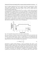
The balance condition between the evaporator and the compressor
can be visualized in a graphic solution, superimposing the basic
rating of the cooler on the compressor curves (see Figure 10.1).
While it is usual to consider only the balance at the maximum
summer ambient, the application engineer should be aware of the
running conditions in cooler weather. If this is not favourable to
300
250
200
150
100
50
0
kW
170 kW
130 kW
W
inter duty
Summer duty
– 25
25°C
40°C
Condensing
temperature
Room
temperature
–
40 – 35 – 30 – 25.5 – 24 – 20 – 15
Evaporating temperature (°C)
Cooler rating
Figure 10.1
Balance condition between compressor and evaporator
Selection and balancing of components
125
the product, some average choice may be made, or a back pressure
valve inserted to prevent the evaporating temperature dropping
too low (see Figure 10.2). A different set of conditions will also
occur if the compressor has capacity control. If this is likely to cause
problems, then a compressor with 50% capacity control may be
connected to two equal evaporators, and one of these shut off at
half load.
Condenser
Compressor
Back pressure
regulating valve
Evaporator
Expansion
valve
Figure 10.2
Use of back pressure regulating valve to maintain
evaporator pressure (and temperature)
10.5 Condenser
A first guess of a condensing temperature has already been taken as
a rough guide. Users should be aware of the wide difference in
owning costs arising from the choice of condenser, so the options
should be compared. The buyer who is influenced only by first cost
will almost certainly face higher fuel bills. Certain machines, such
as the centrifugal compressor, are very sensitive to high condensing
conditions, and the correct choice (in this case, of a cooling tower)
can give a considerable gain in COP.
Users seeking tender quotations should demand relative running
costs and make their decision on the basis of their anticipated running
times and so of the expected fuel costs, taking into account the slow
inflation of electricity tariffs. Buyers must be aware of the tendency
of a contractor to offer only one make or type of equipment, and
where this situation arises, alternative tenders should be sought.
In most climates the wet bulb temperature is well below the dry
bulb temperature and there is an advantage in using water or
evaporative cooling for larger plant. These options need to be
investigated and compared. The present concern over spray-borne
diseases may indicate a preference for air cooling in the vicinity of
institutions but correct maintenance of water cooling towers and
evaporative condensers will permit their use elsewhere. Table 10.2,
based on the tentative temperature differences of 15
K and 12 K
126
Refrigeration and Air-Conditioning
given above, shows that such figures need to be reconsidered in
extreme cases. For example, if it is necessary to use an air-cooled
condenser in the desert, because there is no water available, then
there will be considerable economy in oversizing the condenser to
reduce the condensing temperature from a first guess of 62°C down
to, possibly, 56°C.
Some manufacturers of air-cooled packaged condensing units
offer a range of condenser sizes for each compressor, and these
should be closely compared in terms of higher duty and lower
running costs.
The maximum design condensing temperature will only apply
when the ambient is at its hottest, and full advantage should always
be taken to allow this temperature to drop at cooler times, down to
its minimum working limit (see also [8–10]). Systems should be
allowed to drop to a condensing temperature of 25°C when the
cooling medium permits this, and some systems can go a lot lower.
A true estimate of owning cost should take this into account.
The performance of alternative condensers with a compressor–
evaporator system can be shown graphically but the curves will have
to be plotted, since manufacturers cannot be expected to supply
these figures for all conditions of working. In this construction
(Figure 10.3) the rating curves are the rejected heat from the
compressor, i.e. cooling duty plus compressor power. These are
plotted against the basic rating of the condenser. Some condenser
manufacturers provide rating curves based on the cooling capacity
of the compressor and using typical factors for the power (see Example
6.2).
Air-cooled condensers require a large air flow for a given heat
rejection duty and the limitation on their use is reached on account
of their size and the need to get enough air. Water or evaporative
cooling should always be considered as a possibility, except for smaller
sizes or where using packaged condensing units.
Table 10.2
Climate Air-cooled Evaporative
Dry bulb Condenser Wet bulb Condenser
(°C) (°C) (°C) (°C)
South UK 27 42 21 33
Scotland 24 39 18 30
Mediterranean 32 47 24 36
Desert 47 62 24 36
Tropical humid 33 48 28 40
Selection and balancing of components
127
10.6 Expansion valve
The expansion valve is a passive orifice, through which the liquid
refrigerant is forced by the pressure difference between the
condensing and evaporating conditions. Capacity ratings are given
in the catalogues of manufacturers and suppliers. Types in general
use are:
1. Capillary tubes, for small hermetic systems. These are factory
selected and cannot be adjusted.
2. Solenoid valves with liquid level sensors or liquid level valves for
most flooded evaporators.
3. High-pressure float valves plus handset throttle valves for some
flooded and low-pressure receiver circuits.
4. Thermostatic expansion valves or electronic expansion valves
for most dry expansion circuits.
Troubles arise with the selection of thermostatic expansion valves,
since this is the type generally used in custom-built systems and, for
these, selected outside a factory.
Evap – 30°C
Evap – 35°C
Condenser rating
30
25
20
15
Total rejected condenser heat (kW)
Model PLE08
(from ratings
in Table 4.1)
25 30 35 40 45
Ambient
27°C
Condensing temperature (°C)
Figure 10.3
Balance with condenser
128
Refrigeration and Air-Conditioning
It is usual to select a thermostatic expansion valve for the maximum
duty and at the summer condensing condition, taking into account
the pressure drop through a liquid distributor in the case of a
multiple-feed coil. Valve ratings are given for a range of pressure
differences, i.e. for a range of condensing conditions, in Table 10.3.
It might be thought that the duty varies with pressure difference
according to fluid flow laws, but this valve capacity is plotted against
the expected mass flow curve in Figure 10.4. It is seen that the valve
capacity is greater. This is because the refrigerant can absorb more
heat if it is colder on entry. This means that the valve may be able
to pass the required amount of liquid at a much lower condensing
pressure. Conversely, if the valve is selected at a lower pressure
difference (possibly corresponding to a condensing condition in
the UK of 20–25°C), the valve will not be grossly oversized at the
maximum summer condition.
Rated valve duty
Fluid flow law
1.25
1.00
0.75
0.50
Valve duty (kW)
02468101214
Pressure difference (bar)
Figure 10.4
Rating curve for expansion valve
Table 10.3
Pressure difference
(bar) 2 4 6 8 10 12 14
Valve duty
(kW) 0.77 0.95 1.08 1.16 1.22 1.24 1.26
Unless a thermostatic expansion valve is very tightly rated, the
system will operate satisfactorily at a lower condensing condition in
cool weather, with a gain in compressor duty and lower power input.
A growing awareness of energy economy is leading to more careful
application of this component. Suppliers are ready to help with
advice and optimum selections.
Selection and balancing of components
129
A greater difficulty arises where the compressor may go down to
33% or 25% capacity and the thermostatic expansion valve is called
upon to control a much reduced flow. Under such conditions, the
thermostatic expansion valve may be unstable and ‘hunt’, with slight
loss of evaporator efficiency. Since the required duty is less, this is
of no great importance. It is possible to fit two expansion valves in
parallel, one for the minimum load and both for the full load, but
this arrangement is not usually necessary.
Low condensing pressure operation should present no problem
with float or electronic expansion valves, since these can open to
pass the flow of liquid if correctly sized.
10.7 Sizing pipe and other components
Refrigeration system pipes are sized to offer a low resistance to flow,
since this reflects directly on compression ratio, commensurate with
economy of pipe cost and minimum flow velocities to ensure oil
return with the halocarbons.
Pressure losses due to pipe friction can be calculated from the
basic formulas established by Reynolds and others. However, as
with the calculation of heat transfer factors, this would be a time-
consuming process and some of the parameters are not known
accurately. Recourse is usually made to simplified estimates or tables
published in works of reference [32, 33].
Example 10.1 A suction pipe for an R.502 system, evaporating at
–
40°C and having a cooling duty of 50 kW, is to be run in copper
tube. What size should it be? Reference 32, Chapter 3, Table 3,
shows that a copper tube of 79 mm nominal bore
(3 o.d.)
1
8
″
will
carry R.502 suction gas for a cooling capacity of 51.86 kW, with a
pressure drop of 23 kPa per 100 m run. This is given as a commercially
acceptable pressure loss.
Pressure drops on the high-pressure side will be small enough to
have little effect on the performance of the complete system. Pressure
losses in the suction pipe and its fittings, especially if this is long,
should be checked, and a correction made for the actual compressor
suction pressure. For low-temperature applications, pipe sizes may
have to be increased to avoid excessive frictional losses at these low
pressures.
Flow control valves, such as back pressure valves, will not necessarily
be the same nominal size as the pipe in which they are fitted. Manu-
facturers’ data for selection of their products is usually very compre-
hensive, and their guidance should be sought in case of any doubt.
130
Refrigeration and Air-Conditioning
10.8 Recheck components
In the course of carrying through an equipment selection of this
sort, several options may be tried. It is essential to make a final
check on those selected to ensure that the correct balance has been
achieved. Predicted balance figures should be noted, to guide the
final commissioning process and subsequent operation.
11 Materials. Construction.
Site erection
11.1 Materials
Materials used in the construction of refrigeration and air-
conditioning systems are standard engineering materials, but there
are a few special points of interest:
1. Compressors are generally of gray cast iron, but some makes are
fabricated from mild steel.
2. Compressor pistons are of cast iron or aluminium, the latter
following automobile practice.
3. Piping for the smaller halocarbon installations is usually of copper,
because of the cleanliness and the ease of fabrication and jointing.
4. Some stainless steel pipe is used, mainly because of its cleanliness,
although it is difficult to join.
5. Most other piping will be of mild steel. For working temperatures
below –
45°C, only low-carbon steels of high notch strength are
used (mainly to BS.3603).
6. Aluminium tube is used to a limited extent, with the common
halocarbons and also with ammonia.
7. Copper and its alloys are not used with ammonia.
8. Sheet steel for ductwork, general air-conditioning components,
and outdoor equipment is galvanized.
Specific guidance on materials and their application may be had
from various works of reference [4, 16, 29, 30].
11.2 Pressure tests for safety
Factory-built equipment will be constructed to the relevant Standards
and will be pressure tested for safety and leaks at the works. In cases
of doubt, a test certificate should be requested for all such items.
132
Refrigeration and Air-Conditioning
Design and test pressures will depend on the refrigerant or other
fluids used.
Site-assembled plant will be pressure tested for safety and leakage
after erection (see Section 11.11).
11.3 Erection programme
Successful site erection of plant demands coordination of the
following:
1. Site access or availability
2. Supply on time, and safe storage, of materials
3. Availability of layout drawings, flow diagrams, pipework details,
control and wiring circuits, material lists and similar details
4. Availability at the correct time of specialist trades and services –
builders, lifting equipment, labourers, fitters, welders, electricians,
commissioning engineers, etc.
Site work is now mostly carried out by a number of subcontractors
representing specialist trades. It is essential that authority and
executive action are in the hands of a main contractor and that this
authority is acknowledged by the subcontractors. If this is not so,
delays and omissions will occur, with divided responsibility and lack
of remedial action.
The controlling authority must, well before the start of site erection,
draw up a material delivery and progress chart and see that all
subcontractors (and the customer) are in agreement and that they
are kept informed of any changes [31].
11.4 Pipe-joining methods
Steel pipe is now entirely welded, except for joints which need to be
taken apart for service, which will be flanged. It is essential that
welding is carried out by competent craftsmen and is subject to
stringent inspection [29, 30].
Flanges for ammonia (and preferably, also, for other refrigerants)
must be of the tongued-and-grooved type which trap the gasket.
Mechanical joints for copper tube up to
3
4
inch outside diameter
can be of the flare type, in which the tube end is coned out to form
its own gasket. This must be carried out with the proper flare tools,
and it may be necessary to anneal the tube to ensure that the
resulting cone gasket is soft.
Copper tube can be bent to shape in the smaller sizes and the use
of bending springs or formers is advised, to retain the full bore.
Materials. Construction. Site erection
133
Where fittings are required, these should be of copper or brass to
give a correct capillary joint gap of not more than 0.2 mm, and
joined with brazing alloy. This, again, is a craft not to be entrusted
to the semi-skilled.
The brazing of copper tube will leave a layer of copper oxide
inside, which may become detached and travel around the circuit.
The best practice is to pass nitrogen into the pipe before heating,
to avoid this oxidation. The use of special grades of oxygen-free or
moisture-free nitrogen is not necessary.
11.5 Piping for oil return
The sizing and arrangement of suction and discharge piping for
the halocarbons is dominated by the need to ensure proper
entrainment of oil, to return this to the compressor. Pipes for these
gases usually have a higher velocity at the expense of a greater
pressure drop than those for ammonia. Pipe sizes may only be
increased in runs where the oil will be assisted by gravity to flow in
the same direction as the gas.
Horizontal pipes should slope slightly downwards in the direction
of flow, where this can be arranged. If a suction or discharge line
has to rise, the size may be decreased to make the gas move faster.
In the case of a lift of more than 5 m, a trap should be formed at the
bottom to collect any oil which falls back when the plant stops [33].
Suction and discharge risers (Figure 11.1) will normally be sized
for full compressor capacity, and velocities will be too low if capacity
reduction is operated. In such installations, double risers are required,
the smaller to take the minimum capacity and the two together to
carry the full flow. Traps at the bottom and goosenecks at the top
complete the arrangement. At part capacity, any oil which is not
carried up the main riser will fall back and eventually block the trap
at the bottom, leaving the smaller pipe to carry the reduced flow,
with its quota of oil. When the system switches back to full capacity,
the slug of oil in this trap will be blown clear again.
11.6 Pipe supports. Valve access
Piping must be properly supported at frequent intervals to limit
stress and deflection [10]. Supports must allow for expansion and
contraction which will occur in use. In particular, pipework which
might form a convenient foothold for persons clambering about
the plant should be protected from damage by providing other
footholds and guarding insulation.
Stop valves, especially those which might need to be operated in
134
Refrigeration and Air-Conditioning
a hurry (and this means most, if not all, of them), should have easy
access. Where they are out of reach, reliance should not be placed
on moveable ladders, which may not be there when needed, but
permanent access provided. Chain-operated wheels can be fitted to
the larger valves, to permit remote operation.
Emergency stop valves must not be placed in tunnels or ducts,
since personnel may be subject to additional danger trying to operate
them.
11.7 Instruments
Until recently it has been the custom to fit thermometer wells at
various points in the pipework, to enable check temperatures to be
taken during initial commissioning and also during the life of the
plant. The advent of the electronic probe thermometer has simplified
commissioning work, and the fitting of thermometer wells is less
important. Even so, such facilities are worth considering when the
pipe is being erected, and will be necessary with insulated pipes if
true temperatures are to be taken without damaging the insulation.
Wells should slope downwards into the pipe, so that they can be
part filled with liquid to provide better thermal contact. Where a
pipe temperature is a critical factor in the operation of a system, it
is usually worth fitting a permanent thermometer.
The monitoring of temperatures for electronic control systems is
now mainly by thermocouples, secured onto the outside of the pipe
with self-adhesive tape and the pipe then insulated over.
Smaller
riser
sized for
minimum
flow
Oil trap
Oil trap
Figure 11.1
Gas risers for oil return
Materials. Construction. Site erection
135
Pressure gauges should always be fitted on the discharge side of
liquid pumps, to check performance and give warning of a possible
drop in flow resulting from dirty strainers. Manometer pressure
gauges are required across air filters (see Chapter 27).
11.8 Rising liquid lines
If liquid refrigerant has to rise from the condenser or receiver to an
expansion valve at a higher level, there will be a loss of static head,
and the refrigerant may reach its boiling point and start to flash off.
Under such circumstances, bubbles will show in the sight glass and
will not be dispersed by adding more refrigerant to the system.
Example 11.1 R.22 condenses in a circuit at 34°C and is subcooled
to 30°C before it leaves the condenser. How much liquid lift can be
tolerated before bubbles appear in the liquid line?
Saturation pressure at 34°C = 13.21 bar
Saturation pressure at 30°C = 11.92 bar
Permissible pressure drop = 1.29 bar (129 000 Pa)
Specific mass of liquid = 1162 kg/m
3
Possible loss in static head =
129 000
9.81 1162×
(where g = 9.81 m/s
2
)
= 11.3 m approximately
Where a high lift cannot be avoided, the liquid must be subcooled
enough to keep it liquid at the lower pressure. Subcooling can be
accomplished by fitting a subcooling coil to the condenser, a water-
cooled subcooling coil, a suction-to-liquid heat exchanger before
the lift, or a refrigerated subcooler.
To reduce the risk of these troubles, the condenser should always
be higher than the evaporator, if this can be arranged.
The same effect will occur where the liquid line picks up heat on
a horizontal run, where it may be in the same duct as hot pipes, or
pass through a boilerhouse. If the sight glass flashes even with the
addition of refrigerant, the possibility of such extra heating should
be investigated. To cure this, insulate the pipe.
11.9 Vibration
Compressors and pumps will transmit vibration to their connecting
pipework.
136
Refrigeration and Air-Conditioning
Water and brine pumps may be isolated with flexible connectors.
For small-bore pipes, these can be ordinary reinforced rubber hose,
suitably fastened at each end. For larger pipes, corrugated or bellows
connectors of various types can be obtained. In all cases, the main
pipe must be securely fixed close to the connector, so that the latter
absorbs all the vibration. Flexible connectors for the refrigerant
usually take the form of corrugated metal hose, wrapped and braided.
They should be placed as close to the compressor as possible.
A great deal of vibration can be absorbed by ordinary piping up
to 50 mm or 65 mm nominal bore, providing it is long enough and
free to move with the compressor. Three pieces, mutually at right
angles and each 20 diameters long, will suffice. At the end of these
vibration-absorbing lengths, the pipe must be securely fixed.
In all instances of antivibration mounting of machinery, care
must be taken to ensure that other connections – water, electrical,
etc. – also have enough flexibility not to transmit vibration.
11.10 Cleanliness of piping
All possible dirt should be kept out of pipes and components during
erection. Copper pipe will be clean and sealed as received, and
should be kept plugged at all times, except when making a joint.
Use the plastic caps provided with the tube – they are easily seen
and will not be left on the pipe. Plugs of paper and rag tend to be
forgotten and left in place. Steel pipe will have an oily coating when
received, and it is important that this should be wiped out, since the
oil will otherwise finish up in the sump and contaminate the proper
lubricating oil. If pipe is not so cleaned, the compressor oil should
be changed before the plant is handed over.
Rusty pipe should not be used. The rust and loosened mill scale
will travel around the circuit to block the suction strainer and the
drier. Other avoidable debris are loose pieces of weld, flux, and the
short stubs of welding rod often used as temporary spacers for butt
welds. Pipe should only be cut with a gas torch if all the oxidized
metal can be cleaned out again before closing the pipe.
It should be borne in mind that all refrigerants have a strong
solvent effect and swarf, rust, scale, water, oils and other contaminants
will cause harm to the system, and possible malfunction, and shorten
the working life.
11.11 Site pressure safety tests
Site-erected pipework, once complete, must be pressure tested for
safety and freedom from leaks. Pressures will be 1.3 times the
Materials. Construction. Site erection
137
maximum working pressure, and usual figures for the UK are 27.5
bar for the high side of air-cooled plants, 22.75 bar for water-cooled
plants, and 13.75 bar for the evaporator side. These figures are for
R.22 and R.717.
It is necessary to hold a Safe Handling of Refrigerants Certificate
to work with refrigerants. This can be obtained through short training
courses. Maintenance engineers must keep themselves updated on
safety procedures with existing new refrigerants.
Factory-built components and pressure vessels which have already
undergone test should not be retested, unless they form part of the
circuit which cannot be isolated, when the test pressure must not
exceed the original figure. Site hydraulic testing is considered
unnecessary, owing to the extreme difficulty of removing the test
fluid afterwards. However, it must always be appreciated that site
testing with gases is a potentially dangerous process, and must be
governed by considerations of safety. In particular, personnel should
be evacuated from the area and test personnel themselves be
protected from the blast which would occur if a pressure vessel
exploded [30].
Testing should be carried out with nitrogen, and the use of grades
of gas having very low levels of water or oxygen is not necessary. Air
may be used where no oil is present but cannot be recommended, as
it will bring with it a quantity of moisture, which is difficult to remove.
Nitrogen is used from standard cylinders, supplied at about 200
bar, and a proper reducing valve must always be employed to get
the test pressure required. A separate gauge is used to check the
test pressure, since that on the reducing valve will be affected by the
gas flow.
If the high side is being tested, the low side should be vented to
the atmosphere, in case there is any leakage between them which
could bring excessive pressure onto the low side. It may be necessary
to remove relief valves. Other valves within the circuit will have to
be open or closed as necessary to obtain the test pressure. Servo-
operated valves will not open on a ‘dead’ circuit, and must be opened
mechanically.
After the test gas has gone in, there may be a slight change in
pressure with a change of temperature. In particular, if left overnight,
the pressure may drop as much as 1 bar. This is not significant.
The test pressure should be maintained for at least an hour. In
this period a thorough test is made of each joint with soapy water.
This method is no more tedious than a refrigerant leak test and
saves the time and loss of refrigerant. Large leaks will be heard.
138
Refrigeration and Air-Conditioning
11.12 Evacuation
It is now necessary to remove as much as possible of the original air,
with its moisture content, and the test gas, before introducing the
refrigerant. The principle of evacuation is to reduce the pressure of
any water vapour left in the piping to a saturation temperature well
below the operating condition of the system. If this is not done,
water will condense when the piping gets down to working
temperature. These low pressures are expressed in a number of
units, all as absolute pressures, as shown in Table 11.1.
Table 11.1
Temperature Vapour pressure of water, abs
(°C)
(Pa) (mb) (mm Hg) (µmHg)
torr
–
60 1 0.01 0.01 7.5
–
50 4 0.04 0.03 30
–
40 13 0.13 0.10 96
–
30 38 0.38 0.29 285
–
20 103 1.03 0.77 775
–
10 260 2.60 1.95 1950
0 611 6.11 4.5 4585
The test pressure is released and a vacuum pump connected to
draw from all parts of the circuit. This may require two connections,
to bypass restrictions such as expansion valves, and all valves must
be opened within the circuit, requiring electrical supplies to solenoid
valves and the operation of jacking screws, where these are fitted.
On small systems, such as factory packages, a final pressure of
50 µmHg (7 Pa) should be reached, but larger and site installations
for air-conditioning temperatures are acceptable at a final vacuum
of 170 Pa [31]. Vacuum pumps of this quality can be hired if not
immediately available. Evacuation of a large system may take a couple
of days. During this time, checks should be made around the pipework
for cold patches, indicating water boiling off within, and heat applied
to get this away.
Care should be taken that the pump used will tolerate the
refrigerant gas.
11.13 Charging with refrigerant
Refrigerant may be charged as a liquid through the connection
shown in Figure 11.2. The cylinder is connected as shown and the