Nonlinear Finite Elements for Continua and Structures Part 15 docx
Bạn đang xem bản rút gọn của tài liệu. Xem và tải ngay bản đầy đủ của tài liệu tại đây (131.38 KB, 40 trang )
T. Belytschko, Chapter 9, Shells and Structures, December 16, 1998
ˆ
v
x
ˆ
v
y
=
ˆ
v
x
M
ˆ
v
y
M
+ω
ˆ
y
−1
tanθ
(9.4.12)
It can be seen by comparing the above to (9.2.2-3) that when
θ =0
, the above
corresponds exactly to the velocity field of classical Mindlin-Reissner theory, and as long
as
θ
is small, it is a good approximation. However, analysts often let
θ
take on large
values, like
π
4
, by placing the slave nodes so that the director is not aligned with the
normal. When the angle between the director and the normal is large, the velocity field
differs substantially from that of classical Mindlin-Reissner theory.
The acceleration is given by the material time derivative of the velocity:
˙
v =
˙
v
M
+η
˙
ω × p+ω× ω× p
( )
( )
(9.4.9)
so as indicated in (9.3.17), the accelration depends quadratically on the angular velocities.
The dependent variables for the beam are the two components of the midline
velocity,
v
M
ξ,t
( )
and the angular velocity
ω ξ,t
( )
; alternatively one can let the midline
displacement
u
M
ξ,t
( )
and the current angle of the director,
θ ξ,t
( )
, be the dependent
variables. Thus the constraints introduced by the assumptions of the CB beam theory
change the dependent variables from the two translational velocity components to two
translational components and a rotation. However, the new dependent variables are
functions of a single space variable, ξ , whereas the independent variables of the
continuum are functions of two space variables. This reduction in the dimensionality of
the problem is the major benefit of structural theories.
The development of expressions for the rate-of-deformation tensor is somewhat
involved. The following is based on Belytschko, Wong and Stolarski(1989) specialized
to two dimensions. We start with the implicit differentiation formula (4.4.36)
L = v
,x
= v
,ξ
x
,ξ
−1
ˆ
D = sym
∂
ˆ
v
i
∂
ˆ
x
j
=
∂
ˆ
v
x
M
∂
ˆ
x
−
ˆ
y
∂ω
∂
ˆ
x
1
2
∂
ˆ
v
y
M
∂
ˆ
x
−ω +
∂ω
∂
ˆ
x
tanθ
sym ω tanθ
(9.4.13)
The effects of deviations of the director from the normal can be seen by comparing the
above with (9.2.4). The axial velocity strain, which is predominant in bending response,
agrees exactly with the Mindlin-Reissner theory: it varies linearly through the thickness
of the beam, with the linear field entirely due to rotation of the cross-section. However,
the above transverse shear
ˆ
D
xy
and normal velocity strains
ˆ
D
yy
differ substantially from
those of the classical Mindlin-Reissner theory (9.2.4) when the angle
ˆ
θ
between the
director and the normal to the lamina is large. These differences effect the plane stress
9-20
T. Belytschko, Chapter 9, Shells and Structures, December 16, 1998
assumption. The motion associated with the modified Mindlin-Reissner theory can
generate a significant nonzero axial velocity strain through Poisson effects.
The above tortuous approach is seldom used for the calculation of the velocity
strrains in a CB beam. It makes sense only when the nodal internal fores are computed
from resultant stresses. Otherwise the standard continuum expressions given in Chapter 4
are utilized. The objective of the above development was to show the characteristics of
the velocity strain of a CB beam element, particularly its distribution through the
thickness of the beam. The predominantly linear variation of the velocity strains through
the thickness is the basis for developing resultant stresses.
Resultant Stresses. In classical beam and shell theories, the stresses are treated in
terms of their integrals, known as resultant stresses. In the following, we examine the
resultant stresses for CB beam theory, but to make the development more manageable,
we assume the director to be normal to the reference surface, i.e. that
θ =0
. We
consider a curved beam in two dimensions with the reference line parametrized by
r
;
0 ≤ r ≤ L
, where
r
has physical dimensions of length, in contrast to the curvilinear
coordinate ξ , which is nondimensional. To define the resultant stresses, we will express
the virtual internal power (4.6.12) in terms of corotational components of the Cauchy
stress. We omit the power due to
ˆ
σ
yy
, which vanishes due to the plane stress assumption
(4.6.12), giving
δP
int
= δ
ˆ
D
x
ˆ
σ
x
+2δ
ˆ
D
xy
ˆ
σ
xy
)
dAdr
(
A
∫
0
L
∫
(9.4.13b)
In the above, the three-dimensional domain integral has been changed to an area integral
and a line integral over the arc length of the reference line. The above integral is exactly
equivalent to the integral over the volume if the directors at the endpoints are normal to
the reference line. If the directors are not normal to the reference line at the endpoints,
then the volume in (9.4.14) differs from the volume of the continuum element as shown
in Fig. 9.7. This is usually not significant.
reference line
n
p
volume gained
volume lost
Figure 9.7 Comparison of volume integral in CB beam theory with line integral
Substituting (9.4.13b) into (9.4.13) gives
9-21
T. Belytschko, Chapter 9, Shells and Structures, December 16, 1998
δP
int
=
∂ δ
ˆ
v
x
M
( )
∂
ˆ
x
ˆ
σ
xx
A
∫
0
L
∫
−
∂ δω
( )
∂
ˆ
x
ˆ
y
ˆ
σ
xx
+ −δω +
∂ δ
ˆ
v
y
M
( )
∂
ˆ
x
ˆ
σ
xy
dAdr
(9.4.14)
reference line
p
ˆ
y
ˆ
x n
S
m
Figure 9.8. Resultant stresses in 2D beam.
t
x
∗
t
x
∗
t
y
∗
t
y
∗
h
Γ
1
Γ2
b
x
b
y
a
9.9. An example of external loads on a CB beam.
The following area integrals are defined
membrane force n =
ˆ
σ
xx
A
∫
dA
moment m=− y
ˆ
σ
xx
A
∫
dA
shear s
y
=
ˆ
σ
xy
A
∫
dA
(9.4.15)
The above are known as resultant stresses or generalized stresses; they are shown in Fig.
9.8 in their positive directions. The resultant n is the normal force, also called the
9-22
T. Belytschko, Chapter 9, Shells and Structures, December 16, 1998
membrane force or axial force. This is the net force tangent to the midline due to the
stresses in the beam. The moment m is the first moment of the stresses above the
reference line. The shear force s is the net resultant of the transverse shear stresses.
These definitions correspond with the customary definitions in texts on structures or
mechanics of materials.
With these definitions, the internal virtual power (9.4.14) becomes
δP
int
=
∂ δ
ˆ
v
x
M
( )
∂
ˆ
x
n
axial
1 2 4 3 4
+
∂ δω
( )
∂
ˆ
x
m
bending
1 2 4 3 4
+ −δω +
∂ δ
ˆ
v
y
M
( )
∂
ˆ
x
q
shear
1 2 4 4 4 3 4 4 4
0
L
∫
dr
(9.4.16)
The physical names of the various powers are indicated. The axial or membrane power is
the power expended on stretching the beam, the bending power the energy expended on
bending the beam. The transverse shear power arises also from bending of the beam (see
Eq. (???)); it vanishes for thin beams where the Euler-Bernoulli assumption is applicable.
The external power is defined in terms of resultants of the tractions subdivided
into axial and bending power in a similar way. We assume t
z
= 0
and that p is coincident
with
ˆ
y
at the ends of the beam and consider only the tractions for the specific example
shown in Fig. 9.9; the director is assumed collinear with the normal, so only the terms in
classical Mindlin-Reissner theory are developed. The virtual external power is obtained
from (B4.2.5), which in terms of corotational components gives
δP
ext
= δ
ˆ
v
x
ˆ
t
x
∗
+ δ
ˆ
v
y
ˆ
t
y
∗
( )
dΓ +
Γ
1
∪Γ
2
∫
δ
ˆ
v
x
ˆ
b
x
+ δ
ˆ
v
y
ˆ
b
y
( )
dΩ
Ω
∫
(9.4.17)
Substituting Eq. (9.4.12) into the above yields
δP
ext
= δ
ˆ
v
x
M
− δω
ˆ
y
( )
ˆ
t
x
∗
+ δ
ˆ
v
y
M
( )
ˆ
t
y
∗
( )
dΓ
Γ
1
∪Γ
2
∫
+ δ
ˆ
v
x
M
−δω
ˆ
y
( )
ˆ
b
x
+ δ
ˆ
v
y
M
( )
ˆ
b
y
( )
dΩ
Ω
∫
(9.4.18)
The applied forces are now subdivided into those applied to the ends of the beam and
those applied over the interior. For this example, only the right hand end is subjected to
prescribed tractions, see Fig. 9.9. The generalized external forces are now defined
similarly to the resulotant stresses by taking the zeroth and first moments of the tractions:
n
*
=
ˆ
t
x
∗
dA,
Γ
1
∫
s
*
=
ˆ
t
y
∗
dA,
Γ
1
∫
m
*
=−
ˆ
y
ˆ
t
x
∗
Γ
1
∫
dA
= (9.4.19)
where the last equality follows from the fact that the director is assumed normal to the
midline at the boundaries. The tractions between the end points and the body forces are
subsumed as generalized body forces
9-23
T. Belytschko, Chapter 9, Shells and Structures, December 16, 1998
ˆ
f
x
=
ˆ
t
x
∗
dΓ +
ˆ
b
x
dΩ
Ω
∫
,
Γ
2
∫
ˆ
f
y
=
ˆ
t
y
∗
dΓ+
ˆ
b
y
dΩ
Ω
∫
,
Γ
2
∫
M =−
ˆ
y
ˆ
t
x
∗
Γ
2
∫
dΓ+
ˆ
y
ˆ
b
y
dΩ
Ω
∫
(9.4.20)
Since the dependent variables have been changed from v
i
x, y
( )
to v
i
M
r
( )
and ω r
( )
by the
modified Mindlin-Reissner constraint, the definitions of boundaries are changed
accordingly: the boundaries become the end points of the beam. Any loads applied
between the endpoints are treated like body forces. The boundaries with prescribed
forces are denoted by Γ
n
, Γ
m
andΓ
s
which are the end points at which the normal (axial)
force, moment, and shear force are prescribed, respectively. The external virtual power
(9.4.17), in light of the definitions (9.4.19-20), becomes
δP
ext
= δ
ˆ
v
x
ˆ
f
x
+δ
ˆ
v
y
ˆ
f
y
+δωM
( )
dr +
∫
δ
ˆ
v
x
n
*
Γ
n
+δ
ˆ
v
y
s
*
Γ
s
+δωm
*
Γ
m
(9.4.21)
9.3.?. Boundary Conditions. The velocity (essential) boundary conditions for the
CB beam are usually expressed in terms of corotational coordinates so that they have a
clearer physical meaning. The velocity boundary conditions are
ˆ
v
x
M
=
ˆ
v
x
M∗
on Γ
ˆ
v
x
ˆ
v
y
M
=
ˆ
v
y
M∗
on Γ
ˆ
v
y
ω = ω
∗
on Γ
ω
(9.4.18)
where the subscript on
Γ
indicates the boundary on which the particular displacement is
prescribed. The angular velocity. of course, is independent of the orientation of the
coordinate system so we have not superposed hat on it.
The generalized traction boundary conditions are:
n = n
*
on Γ
n
s = s
∗
on Γ
s
m = m
∗
on Γ
m
(9.4.19)
Note that (9.4.18) and (9.4.19) are sequentially conditions on kinematic and kinetic
variables which are conjugate in power. Each pair yields a power, i.e.,
n
ˆ
v
x
M
is the power
of the axial force on the boundary,
s
ˆ
v
y
M
is the power of the transverse force and
mω
is
the power of the moment. Since variables which are conjugatge in power can not be
prescribed on the same boundary, but one of the pair must be prescribed on any
boundary, it follows then that
Γ
n
∪Γ
v
x
=Γ Γ
n
∩Γ
v
x
=0
Γ
s
∪Γ
v
y
= Γ Γ
s
∩Γ
v
y
=0
Γ
m
∪Γ
v
ω
=Γ Γ
m
∩Γ
ω
= 0
(9.4.20)
9-24
T. Belytschko, Chapter 9, Shells and Structures, December 16, 1998
So on a boundary point either the moment or rotation, the normal force or the velocity
ˆ
v
x
M
, the shear or the velocity
ˆ
v
y
M
must be prescribed, but no pair can be described on the
smae boundary. Even for CB beams, boundary conditions are prescribed in terms of
resultants. The velocity boundary conditions can easily be imposed on the nodal degrees
of freedom given in (9.3.22), since the midline velocities correspond to the nodal
velociities. The traction boundary conditions are
Weak Form. The weak form for the momentum equation for a beam is given by
δ P
inert
+δ P
int
= δ P
ext
∀ δv
x
, δv
y
, δω
( )
∈U
0
(9.4.21)
where the virtual powers are defined in (9.4.16)and (9.4.21) and
U
0
is the space of
piecewise differentiable functions, i.e.
C
0
functions, which vanish on the corresponding
prescribed displacement boundaries. The functions need only be
C
0
since only the first
derivatives of the dependent variables appear in the virtual power expressions.
Strong Form. We will not derive the strong form equivalent to (9.4.21) for an
arbitrary geometry. This can be done, see Simo and Fox(1989) for example, but it is
awkward without curvilinear tensors. Instead, we will develop the strong form for a
straight beam of uniform cross-section which lies along the x-axis, with inertia and
applied moments neglected. Equation (9.4.21) can then be simplified to
δv
x,x
n +δω
,x
m+ δv
y,x
−δω
( )
s −δv
x
f
x
−δv
y
f
y
( )
0
L
∫
dx
− δv
x
n
*
( )
Γ
n
− δωm
*
( )
Γ
m
− δv
y
s
*
( )
Γ
s
= 0
(9.4.22)
The hats have been dropped since the local coordinate system coincides with the global
system at all points. The procedure for finding the equivalent strong form then parallels
the procedure used in Section 4.3. The idea is to remove all derivatives of test functions
which appear in the weak form, so that the above can be written as products of the test
functions with a function of the resultant forces and their derivatives. This is
accomplished by using integration by parts, which is sketched below for each of the terms
in the weak form:
δv
x,x
n
0
L
∫
dx = −δv
x
n
,x
0
L
∫
dx + δv
x
n
( )
Γ
n
+ δv
x
n
(9.4.23)
δω
, x
m
0
L
∫
dx = −δωm
,x
0
L
∫
dx + δωm
( )
Γ
m
+ δωm
(9.4.24)
δv
y, x
s
0
L
∫
dx = −δv
y
s
,x
0
L
∫
dx + δv
y
s
( )
Γ
s
+ δv
y
s
(9.4.25)
In each of the above we have used the fundamental theorem of calculus as given in
Section 2.? for a piecewise continuously differentiable function and the fact that the test
9-25
T. Belytschko, Chapter 9, Shells and Structures, December 16, 1998
functions vanish on the prescribed displacement boundaries, so the boundary term only
applies to the complementary boundary points, which are given by (9.4.20). Substituting
(9.4.23) to (9.4.25) into (9.4.22) gives
δv
x
n
,x
+ f
x
( )
+ δω m
,x
+ s
( )
+ δv
y
s
,x
+ f
y
( )
( )
0
L
∫
dx +δv
x
n +δv
y
s +
δω m +−δv
x
n
*
−n
( )
Γ
n
+δω m
*
− m
( )
Γ
m
+δv
y
s
*
− s
( )
Γ
s
= 0
(9.4.26)
Using the density theorem as given in Section 4.3 then gives the following strong form:
n
,x
+ f
x
= 0, s
,x
+ f
y
= 0, m
,x
+ s = 0,
n = 0, s = 0, m =0
n = n
*
on Γ
n
, s = s
*
on Γ
s
, m=m
*
onΓ
m
(9.4.27)
which are respectively, the equations of equilibrium, the internal continuity conditions,
and the generalized traction (natural) boundary conditions.
The above equilibrium equations are well known in structural mechanics. These
equilibrium equations are not equivalent to the continuum equilibrium equations,
σ
ij, j
+ b
i
= 0
. Instead, they are a weak form of the continuum equilibrium equations.
Their suitability for beams is primarily based on experimental evidence. The error due to
the structural assumption can not be bounded rigorously for arbitrary materials. Thus the
applicability of beam theory, and by extension the shell theories to be considered later,
rests primarily on experimental evidence.
Finite Element Approximation. When the motion is treated in the form (9.4.1) as
a function of a single variable, the finite element approximation is constructed by means
of one-dimensional shape functions N
I
ξ
( )
:
x ξ,η, t
( )
= x
I
M
t
( )
+η
I
p
I
t
( )
( )
I=1
n
N
∑
N
I
ξ
( )
(9.4.24)
As is clear from in the above, the product of the thickness with the director is
interpolated. If they are interpolated independently, the second term in the above is
quadratic in the shape functions and differs from (9.3.2a). It follows immediately from
the above that the original configuration of the element is given by
X ξ, η
( )
= X
I
M
+η
I
p
I
0
( )
I=1
n
N
∑
N
I
ξ
( )
(9.4.25)
The displacement is obtained by taking the difference of (9.4.24) and (9.4.25),
which gives
u ξ, η,t
( )
= u
I
M
t
( )
+η
I
p
I
t
( )
−p
I
0
( )
( )
I=1
n
N
∑
N
I
ξ
( )
9-26
T. Belytschko, Chapter 9, Shells and Structures, December 16, 1998
Taking the material time derivative of the above gives the velocity
v ξ,η,t
( )
= v
I
M
t
( )
+η
I
ωe
z
×p
I
t
( )
( )
( )
I=1
n
N
∑
N
I
ξ
( )
This velocity field is identical to the velocity field generated by substituting (9.3.6) into
(9.5.2b). Thus the mechanics of any element generated by this approach will be identical
to that of an element implemented directly as a continuum element with the modified
Mindlin-Reissner constraints applied only at the nodes, i.e. with the modified Mindlin-
Reissner assumptions applied to the discrete equations. Therefore we will not pursue this
approach further.
(1 ),1
+
2
(
)
,1
−
(3 ),2
−
(4 ),2
+
1
2
θ
1
0
θ
2
0
1
+
1
−
2
−
2
+
1
2
e
1
e
2
p
1
p
2
ξ
η
1
2 3
4
master nodes
slave nodes
x
=
N
I
(
ξ
)x
I
initial config.
current config.
parent element
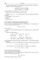
Fig. 9.10 Two-node CB beam element based on 4-node quadrilateral continuum element.
Example 9.1 Two-node beam element. The CB beam theory is used to formulate
a 2-node CB beam element based on a 4-node, continuum quadrilateral. The element is
shown in Fig. 9.10. We place the reference line (midline) midway between the top and
bottom surfaces; the line coincides with ξ =0 in the parent domain; although this
placement is not necessary it is convenient. The master nodes are placed at the
intersections of the reference line with the edges of the element. The slave nodes are the
9-27
T. Belytschko, Chapter 9, Shells and Structures, December 16, 1998
corner nodes and are labeled by the two numbering schemes described previously in Fig.
9.10.
This motion of the 4-node continuum element
x = x
I
I=1
4
∑
t
( )
N
I
ξ,η
( )
(E9.1.2)
where
N
I
ξ,η
( )
are the standard 4-node isoparametric shape functions
N
I
ξ,η
( )
=
1
4
1+ξ
I
ξ
( )
1+η
I
η
( )
(E9.1.3)
The motion of the element when given in terms of one-dimensional shape functions by
(9.3.3) is:
x ξ,η, t
( )
= x
M
ξ, t
( )
+η p ξ, t
( )
= x
1
t
( )
1−ξ
( )
+ x
2
t
( )
ξ +η p
1
t
( )
1−ξ
( )
+η p
2
t
( )
ξ
(E9.1.1)
Eqs. (E9.1.1) and (E9.1.3) are equivalent if
x
1
t
( )
=
1
2
x
1
+ x
2
( )
=
1
2
x
1
+
+ x
1
−
( )
x
2
t
( )
=
1
2
x
3
+ x
4
( )
=
1
2
x
2
+
+ x
2
−
( )
(E9.1.4)
p
1
t
( )
=
x
2
− x
1
( )
e
x
+ y
2
− y
1
( )
e
y
x
2
− x
1
( )
2
+ y
2
− y
1
( )
2
( )
1/2
p
2
t
( )
=
x
4
− x
3
( )
e
x
+ y
4
− y
3
( )
e
y
x
4
− x
3
( )
2
+ y
4
− y
3
( )
2
( )
1/2
(E9.1.5a)
Thus the motions given in Eqs. (E9.1.2) and (E9.1.3) are alternate descriptions of
the same motion. Eqs. (E9.1.4) define the location of the master nodes. Eqs. (E9.1.5)
define the orientations of the directors.
The degrees of freedom of this CB beam element are
d
T
= u
x1
, u
y1
,θ
1
,u
x2
, u
y2
,θ
2
[ ]
(E9.1.6)
where θ
I
are the angles between the directors and the x-axis measured positively in a
counterclockwise direction from the positive x-axis. The nodal velocities are
˙
d
T
=
˙
u
x1
,
˙
u
y1
, ω
1
,
˙
u
x2
,
˙
u
y2
,ω
2
[ ]
(E9.1.7)
The nodal forces are conjugate to the nodal velocities in the sense of power, so
f
T
= f
x1
, f
y1
,m
1
, f
x2
, f
y2
,m
2
[ ]
(E9.1.8)
9-28
T. Belytschko, Chapter 9, Shells and Structures, December 16, 1998
where m
I
are nodal moments.
The nodal velocities of the slave nodes are next expressed in terms of the master
nodal velocities by (9.3.7). The relations are written for each triplet of nodes: a master
node and the two associated slave nodes. For each triplet of nodes, the (9.3.7) specialized
to the geometry of this example is
v
I
S
= T
I
v
I
M
(no sum on I) (E9.1.9)
where
v
I
S
=
v
xI
−
v
yI
−
v
xI
+
v
yI
+
, T
I
=
1 0
h
2
p
x
0 1 −
h
2
p
y
1 0 −
h
2
p
x
0 1
h
2
p
y
=
1 0
1
2
y
1 2
0 1
1
2
x
2 1
1 0
1
2
y
3 4
0 1
1
2
x
4 3
, v
I
M
=
v
xI
v
yI
θ
I
(E9.1.10)
Once the slave node velocities are known, the rate-of-deformation can be computed at
any point in the element by Eq. (E4.2.c).
The rate-of-deformation is be computed at all quadrature points in the corotational
coordinate system of the quadrature point. The two node element avoids shear locking if
a single stack of quadrature points
ξ = 0, η
Q
( )
, Q = 1 to n
Q
. The strain measures are
computed in the global coordinate system using the equation given in Example 4.2 and
4.10.
The constitutive equation is evaluated at the quadrature points of the element in a
corotational coordinate system given by Eq. (9.3.9) with
ˆ
e
x
=
x,
ξ
e
x
+ y
,ξ
e
y
x,
ξ
( )
2
+ y
,ξ
( )
2
1
2
ˆ
e
y
=
ˆ
e
z
×
ˆ
e
x
(E9.1.11)
where
x,
ξ
= x
I
N
I ,ξ
I =1
4
∑
y,
ξ
= y
I
N
I ,ξ
I =1
4
∑
(E9.1.13)
A hypoelastic law for isotropic and anisotropic laws is given by (9.3.11) or (9.3.13),
respectively.
The internal forces are then transformed to the master nodes for each triplet by
(4.5.36). This gives
9-29
T. Belytschko, Chapter 9, Shells and Structures, December 16, 1998
f
xI
f
yI
m
I
= T
I
T
f
xI
+
f
yI
+
f
xI
−
f
yI
−
(E9.1.14)
Evaluating the first and third term of the above left hand matrix gives
f
xI
= f
xI
+
+ f
xI
−
f
yI
= f
yI
+
+ f
yI
−
(E.9.1.15a)
m
1
=
1
2
y
1 2
f
x1
+ x
2 1
f
y1
( )
(E.9.1.15b)
So the transformation gives what is expected from equilibrium of the slave node with the
master node. The master node force is the sum of the slave node forces and the master
node moment is the moment of the slave node forces about the master node.
This element formulation can also be applied to constitutive equations in terms of
the PK2 stress and the Green strain. The computation of the Green strain tensors requires
the knowledge of θ
I
and x
I
. The director in the initial and current configurations is given
by
p
xI
0
=cosθ
I
0
, p
yI
0
= sin θ
I
0
p
xI
=cosθ
I
, p
yI
= sinθ
I
(E9.1.11)
The positions of the slave nodes can then be computed by specializing (9.4.1) to the
nodes, which gives
X
1
= X
1
+
h
2
p
x1
, Y
1
= Y
1
+
h
2
p
y1
0
X
2
= X
1
−
h
2
p
x1
0
, Y
2
= Y
1
−
h
2
p
y1
0
X
3
= X
2
−
h
2
p
x2
0
, Y
3
= Y
2
−
h
2
p
y2
0
X
4
= X
2
+
h
2
p
x2
0
, Y
4
= Y
2
+
h
2
p
y2
0
x
1
= x
1
+
h
2
p
x1
, y
1
= y
1
+
h
2
p
y1
x
2
= x
1
−
h
2
p
x1
, y
2
= y
1
−
h
2
p
y1
x
3
= x
2
−
h
2
p
x2
, y
3
= y
2
−
h
2
p
y2
x
4
= x
2
+
h
2
p
x2
, y
4
= y
2
+
h
2
p
y2
(E9.1.12)
The displacement of the slave nodes is then obtained by taking the difference of the nodal
coordinates. The displacement of any point can then be obtained by the continuum
displacement field
u = u
I
I=1
4
∑
N
I
The Green strain can then be computed by (3.3.6) and the PK2 stress by the constitutive
law. After transforming the PK2 stress to the Cauchy stress by Box 3.2, the nodal forces
can be computed as before.
Velocity Strains for Rectangular Element. When the underlying continuum element is
rectangular (because the directors are in the y direction), and the beam is along the x
direction, the velocity field (9.4.8) is
9-30
T. Belytschko, Chapter 9, Shells and Structures, December 16, 1998
v = v
M
− yωe
x
where we have specialized Eq. (9.4.8) to θ =π 2. Writing out the components of the
above and immediately substituting the one-dimensional two-node shape functions gives
v
x
= v
x1
M
1−ξ
( )
+ v
x2
M
ξ − y ω 1−ξ
( )
−ω
2
ξ
( )
v
y
= v
y1
M
1−ξ
( )
+ v
y2
M
ξ
The velocity strain is then given by Eq. (3.3.10):
D
xx
=
∂v
x
∂x
=
1
l
v
x2
M
− v
x1
M
( )
−
y
l
ω
2
− ω
1
( )
2D
xy
=
∂v
y
∂x
+
∂v
x
∂y
=
1
l
v
y2
M
− v
y1
M
( )
− ω
1
1−ξ
( )
+ω
2
ξ
( )
D
yy
= 0
The material tangent and goemetric stiffness of this elementis given by LIU-give result
with some explanation
9.5 CONTINUUM BASED SHELL IMPLEMENTATION
In this Section, the degenerated continuum (CB) approach to shell finite elements is
developed. This approach was pioneered by Ahmad(1970); a nonlinear version of this
theory was presented by Hughes and Liu(1981). In the CB approach to shell theory, as
for CB beams, it is not necessary to develop the complete formulation, i.e. developing a
weak form, discretizing the problem by using finite elemeny interpolatns, etc. Instead the
shell element is developed in this Section by imposing the constraints pf the shell theory
on a continuum element. Subsequently, we will examine CB shells from a more
theoretical viewpoint by imposing the constraints on thhe test and trial functions prior to
construction of the weak form.
Assumptions in Classical Shell Theories. To describe the kinematic assumptions for
shells, we need to define a reference surface, often called a midsurface. The reference
surface, as the second name implies, is generally placed midway between the top and
bottom surfaces of the shell. As in nonlinear beams, the exact placement of the reference
surface in nonlinear shells is irrelevant.
Before developing the CB shell theory, we briefly review the kinematic
assumptions of classical shell theories. Similar to beams, there are two types of
kinematic assumptions, those that admit transverse shear and those that don't. The theory
which admit transverse shear are called Mindlin-Reissner theories, whereas the theory
which does not admit transverse shear is called Kirchhoff-Love theory. The kinematic
assumptions in these shell theories are:
1. the normal to the midsurface remains straight (Mindlin-Reissner theory).
2. the normal to the midsurface remains straight and normal (Kirchhoff-Love
theory)
9-31
T. Belytschko, Chapter 9, Shells and Structures, December 16, 1998
Experimental results show that the Kirchhoff-Love assumptions are the most
accurate in predicting the behavior of thin shells. For thicker shells, the Mindlin-Reissner
assumptions are more accurate because transverse shear effects become important.
Transverse shear effects are particularly important in composites. Mindlin-Reissner
theory can also be used for thin shells: in that case the normal will remain approximately
normal and the transverse shears will almost vanish.
One point which needs to be made is that these theories were originally developed
for small deformation problems, and most of their experimental verification has been
made for small strain cases. Once the strains are large, it is not clear whether it is better
to assume that the current normal remains straight or that the initial normal remains
straight. Currently, in most theoretical work, the initial normal is assumed to remain
straight. This choice is probably made because it leads to a cleaner theory. We know of
no experiments that show an advantage of this assumption over the assumption that the
current normal remain instantaneously straight.
Degenerated Shell Methodology. In the implementation and theory of CB shell elements,
the shell is modeled by a single layer of three dimensional elements, as shown in Fig.
9.11?. The motion is then constrained to reflect the modified Mindlin-Reissner
assumptions.
We consider a shell element, such as the one shown in Fig. 9.11, which is associated with
a three dimensional continnjum element. The parent element coordinates are
ξ
i
,
i =1 to 3; we also use the notation
ξ
1
≡ ξ
,
ξ
2
≡ η
, and
ξ
3
≡ ζ
. In the shell, the
coordinates
ξ
i
are curvilinear coordinates. The midsurface is the surface given by
ζ = 0
.
Each surface of constant
ζ
is called a lamina. The reference surface is parametrized by
the two curvilinear coordinates
ξ,η
( )
or ξ
α
in indicial notation (Greek letters are used for
indices with a range of 2). Lines along the
ζ
axis are called fibers, and the unit vector
along a fiber is called a director. These definitions are analogous to the corresponding
definitions for beams given previously.
In the CB shell theory, the major assumptions are the modified Mindlin-Reissner
kinematic assumption and the plane stress assumption:
1. fibers remain straight;
2. the stress normal to the midsurface vanishes.
Often it is assumed that the fibers are inextensional but we omit this assumption. These
assumptions differs from those of classical Mindlin-Reissner theory in that the rectilinear
constraint applies to fibers, not to the normals. This modification is chosen because, as in
beams, the Mindlin-Reissner kinematic assumption cannot be imposed exactly in a CB
element with
C
0
interpolants. In models based on the modified Mindlin-Reissner theory,
the nodes should be placed so that the fiber direction is as close as possible to normal to
the midsurface.
For thin shells, the behavior of CB shells will approximate the behavior of a
Kirchhoff-Love shell: normals to the midsurface will remain normal, so directors which
are originally normal to the midsurface will remain normal, and the transverse shears will
vanish. The normality constraint is based on physical observations, and even when this
constraint is not imposed on a numerical model, the results will tend towards this
behavior for thin shells.
9-32
T. Belytschko, Chapter 9, Shells and Structures, December 16, 1998
We will consider shells where the deformations are large enough so that the
thickness may change substantially with deformation. The thickness change arises from
the conservation of matter, but is usually imposed on the model through the constitutive
equations, which reflect the conservation of matter. In order to model the thickness
change exactly, it is necessary to integrate the thickness strains along the entire fiber.
Here we present a simpler and computationally less demanding theory which only
accounts for a linear variation of the thickness strain through the depth of the shell. This
is more accurate than theories which incorporate only the overall thickness change and is
usually very accurate, since the major effect which needs to be modeled, in addition to
the thickness change due to elongational straining, are the consequences of the linear
bending field.
The motion of the shell is given by
x ξ,η, ζ,t
( )
= x
M
ξ,η, t
( )
+ζ h
−
p ξ ,η,t
( )
for ζ < 0
(9.5.1a)
x ξ,η, ζ,t
( )
= x
M
ξ,η, t
( )
+ζ h
+
p ξ ,η,t
( )
for ζ > 0
(9.5.1b)
where
h
−
and
h
+
are the distances from the midsurface to the top and bottom surfaces
along the director, respectively. The above will be written in the compact form
x = x
M
+ζ x
B
(9.5.2)
where
x
B
= p
(9.5.2b)
ζ =ζ h
+
when ζ > 0, ζ =ζ h
−
when ζ < 0 (9.5.3)
In the above,
x
B
characterizes the motion due to bending; although this decomposition of
the motio, it becomes more useful for other kinematic quantities.
The coordinates of the shell in the original configuration are obtained by
evaluating (9.5.2) at the initial time
X ξ, η,ζ
( )
= X
M
ξ,η
( )
+ζ p
0
ξ,η
( )
= X
M
+ζ X
B
(9.5.4)
where
p
0
= p ξ,η,0
( )
. The displacement field is obtained by taking the difference of
(9.5.2) and (9.5.4):
u ξ, η,ζ, t
( )
= u
M
+ζ p−p
0
( )
=u
M
+ζ u
B
(9.5.5a)
where
u
M
= x
M
− X
M
u
B
= p− p
0
(9.5.5b)
As can be seen from the above, the bending displacement field
u
B
is the difference
between two unit vectors. Therefore the bending field can be described by two dependent
9-33
T. Belytschko, Chapter 9, Shells and Structures, December 16, 1998
variables. The motion is then described by 5 dependent variables: the three translations
of the midsurface,
u
M
= u
x
M
,u
y
M
,u
z
M
[ ]
and the two dependent variables which describe
the bending displacement,
u
B
, which remain to be defined.
The velocity field is obtained by taking the material time derivative of the
displacement or motion, using (9.2.1) to write the rate of the director:
v ξ,η,ζ ,t
( )
= v
M
ξ,η,t
( )
+ζ ω ξ,η,t
( )
× p+
˙
ζ p
(9.5.6)
The last term in the above represents the change in thickness of the shell. It will not be
retained in the equations of motion, since it represents an insignificant inertia. But it will
be used in updating the geometry, so it will effect the internal nodal forces, which depend
on the current geometry. The variable
˙
ζ
will be obtained from the constitutive equation
or conservation of matter. The velocity field can also be written as
v ξ,η,ζ ,t
( )
= v
M
+ζ v
B
+
˙
ζ p
(9.5.7)
where
v
B
=ζ ω ×p
(9.5.8)
As can be seen from the above, the velocity of any point in the shell consists of the sum
of the velocity of the reference plane, the bending velocity, and the velocity due to the
change in thickness. The bending velocity is defined by the rotation of the director. Only
the two components of the angular velocity in the plane tangent to the director
p
are
relevant. The component parallel to the
p
vector is irrelevant since it causes no change in
the director
p
. This component is called the drilling component or the drill for short.
Local and Corotational Coordinates. Three coordinate systems are defined:
1. the global Cartesian system,
x, y,z
( )
with base vectors e
i
.
2. the corotational Cartesian coordinates
ˆ
x ,
ˆ
y ,
ˆ
z
( )
with base vectors
ˆ
e
i
, which are
constructed so that the plane defined by
ˆ
e
1
ξ,t
( )
and
ˆ
e
2
ξ,t
( )
is tangent to the
lamina As indicated, the corotational base vectors are functions of the
element coordinates and time. In practice, these coordinate systems are
constructed only at the quadrature points of the element, but conceptually, the
corotational coordinate system is defined at every point of the shell. Several
methods have been proposed for the construction of the corotational systems,
and they will be described later.
3. nodal coordinate systems associated with the master nodes; they are denoted
by superposed bars e
iI
t
( )
, where the subscript the node. The nodal
coordinates system is defined by
e
zI
t
( )
= p
I
t
( )
(9.5.9)
The orientation of the two other base vectors is described later.
9-34
T. Belytschko, Chapter 9, Shells and Structures, December 16, 1998
Finite Element Approximation of Motion. The underlying finite element for a
CB shell theory is a three-dimensional isoparametric element with 2n
N
slave nodes. In
order to meet the modified Mindlin-Reissner assumption, the continuum element may
have at most two slave nodes along any fiber. As a consequence of this restriction, the
motion will be linear in ζ
.
The description is Lagrangian and either an updated or total
Lagrangian formulation can be employed. We will emphasize the updated Lagrangian
formulation, but remind the reader that in the updated Lagrangian formulation the strain
can be described by the Green strain tensor and the PK2 stress when it is advantageous
for a particular constitutive law. Moreover any updated Lagrangian formulation can
easily be changed to a Lagrangian formulation by a transformation of stresses and change
in the domain of integration.
The formulation may have either 5 or 6 degrees of freedom per master node. We
will emphasize the 5 degree-of-freedom formulations and discuss the relative merits
later. The degrees of freedom in the 5 degree-of-freedom formulation are
v
I
= v
xI
, v
yI
, v
zI
, ω
xI
, ω
yI
[ ]
T
(9.5.9b)
the
ω
zI
component, the drilling angular velocity component, has been omitted; see
(9.5.9) for the definition of the nodal coordinate system. The nodal forces are conjugate
to the nodal velocities in the sense of power, so they are given by
f
I
= f
xI
, f
yI
, f
zI
, m
xI
, m
yI
[ ]
T
(9.5.9c)
At the intersections of the slave nodal fibers with the reference surface, we define
master nodes as shown in Fig. 9.7. The finite element approximation to the motion in
terms of the motion of the slave nodes is
x ξ
e
, t
( )
≡ φ
h
ξ
e
,t
( )
= x
I
I =1
2n
N
∑
t
( )
N
I
ξ
e
( )
= x
I
+
I
+
=1
n
N
∑
t
( )
N
I
+
ξ
e
( )
+ x
I
−
I
−
=1
n
N
∑
t
( )
N
I
−
ξ
e
( )
(9.5.10)
where N
I
ξ
e
( )
are standard isoparametric, three dimensional shape functions and ξ
e
are
the parent element coordinates. Recall that in a Lagrangian element, the element
coordinates can be used as surrogate material coordinates. The above gives the motion for
a single element; the assembly of element motions to obtain the motion of the complete
body is standard.
Two notations are used for the slave nodes: nodal indices with superposed bars,
which refer to the original node numbers of the underlying three dimensional element and
node numbers with plus and minus superscripts, which refer to the master node numbers.
Nodes
I
+
and
I
−
are, respectively, the slave nodes on the top and bottom surfaces of the
fiber which passes through master node I.
The velocity field of the underlying continuum element is given by
v ξ
e
, t
( )
=
∂φ
h
ξ
e
, t
( )
∂t
=
˙
x
I
I =1
2n
N
∑
t
( )
N
I
ξ
e
( )
(9.5.12)
9-35
T. Belytschko, Chapter 9, Shells and Structures, December 16, 1998
where
˙
x
I
is the velocity of slave node I. To achieve a velocity field compatible with
(9.5.6), the velocity of the slave nodes is given in terms of the translational velocities of
the master nodes
v
I
M
= v
xI
M
,v
yI
M
,v
zI
M
[ ]
T
and the angular velocities of the director
ω
I
= ω
xI
,ω
yI
[ ]
T
by
v
I
+
= v
I
M
+ h
+
ω
I
× p
I
−
˙
h
I
+
p
I
v
I
−
= v
I
M
+ h
I
−
ω
I
× p
I
+
˙
h
I
−
p
I
(9.5.13)
h = h
0
F
ζζ
dζ
0
1
∫
where
˙
h
I
+
and
˙
h
I
−
are the velocities of slave nodes
I
+
and
I
−
in the direction of the
director, respectively. These are obtained from integrating the through-the thickness
strains obtained from the constitutive equation because of the plane stress assumption, as
described later. They are omitted in the formulation of the equations of motion, for
neither momentum balance nor equilibrium is enforced in the direction of
p
.
The relationship between the slave and master nodal velocities
for each triplet of
nodes along a fiber can then be written in matrix form as
v
I
+
v
I
−
=T
I
v
I
no sum on I (9.5.14)
where the vector have been expressed in the nodal coordinate system of the master node
for convenience. For a 5 degree of freedom per node formulation
v
I
+
= v
xI
, v
yI
+
, v
zI
+
[ ]
T
v
I
−
= v
xI
−
, v
yI
−
, v
zI
−
[ ]
T
(9.5.15)
v
I
= v
xI
, v
yI
, v
zI
, ω
xI
, ω
yI
[ ]
(9.5.16)
Τ
I
=
I
3×3
Λ
+
I
3×3
Λ
−
(9.5.17)
Λ
+
= h
I
+
0 1
−1 0
0 0
Λ
−
= h
I
−
0 1
−1 0
0 0
(9.5.18)
For a 6 degree-of-freedom per master node formulation it is more convenient to
write (9.5.14) in terms of global components:
v
I
+
v
I
−
=T
I
v
I
no sum on I (9.5.19)
9-36
T. Belytschko, Chapter 9, Shells and Structures, December 16, 1998
v
I
+
= v
xI
, v
yI
+
, v
zI
+
[ ]
T
v
I
−
= v
xI
−
, v
yI
−
, v
zI
−
[ ]
T
(9.5.20)
v
I
= v
xI
, v
yI
, v
zI
, ω
xI
, ω
yI
,ω
zI
[ ]
(9.5.22)
Λ
+
= h
I
+
0 p
z
−p
y
− p
z
0 p
x
p
y
− p
x
0
=
0 z
I+
− z
I
y
I
−y
I+
z
I
− z
I+
0 x
I+
−x
I
y
I+
− y
I
x
I
− x
I +
0
(9.5.21)
Λ
−
=−h
I
−
0 p
z
−p
y
−p
z
0 p
x
p
y
−p
x
0
=
0 z
I−
−z
I
y
I
− y
I−
z
I
−z
I−
0 x
I−
− x
I
y
I−
− y
I
x
I
− x
I−
0
(9.5.23)
Nodal Internal Forces. The nodal forces at the slave nodes, i.e. the nodes of the
underlying continuum element, are obtained by the usual procedures for continuum
elements, see Chapter 4. Of course, the plane stress assumption and computation of the
thickness change must be considered in the procedures at the continuum level.
The nodal internal and external forces at the master nodes can be obtained from
the slave nodal forces by Eq. (4.3.36), which using (9.5.14) gives
f
I
= T
I
f
I
+
f
I
−
no sum on I (9.5.24)
where for a 6 degree-of-freedom formulation
f
I
= f
xI
, f
yI
, f
zI
, m
xI
, m
yI
, m
zI
[ ]
(9.5.25)
and T
I
is given by (9.5.19-23). In the above, m
iI
are the nodal moments at the master
nodes.
Tangent Stiffness. The tangent stiffness matrix can be obtained from that of the
underlying continuum element by the standard transformation for stiffness matrices,
Section
K
IJ
= T
I
T
K
IJ
T
J
no sum on I or J (9.5.26)
where K
IJ
is the tangent stiffness matrix for the continuum element.
The rate-of-deformation is computed in the corotational coordinates system with base
vectors
ˆ
e
i
. The equations for the rate-of-deformation in the corotational coordinates, ;
are
9-37
T. Belytschko, Chapter 9, Shells and Structures, December 16, 1998
ˆ
D
ij
=
1
2
∂
ˆ
v
i
∂
ˆ
x
j
+
∂
ˆ
v
j
∂
ˆ
x
i
The rate-of-deformation
ˆ
D
zz
is computed from the conservation of mass or the
condition that the normal stress
ˆ
σ
zz
vanishes. This is discussed in more detail in Section
??.
Applying these equations to the velocity field (9.5.6-7) gives
ˆ
D
xx
=
∂
ˆ
v
x
∂
ˆ
x
=
∂
ˆ
v
x
M
∂
ˆ
x
+ζ
∂
ˆ
v
x
B
∂
ˆ
x
≈
ˆ
D
yy
=
∂
ˆ
v
y
∂
ˆ
y
=
∂
ˆ
v
y
M
∂
ˆ
y
+ζ
∂
ˆ
v
y
B
∂
ˆ
y
≈
ˆ
D
xy
=
1
2
∂
ˆ
v
x
∂
ˆ
y
+
∂
ˆ
v
y
∂
ˆ
x
=
1
2
∂
ˆ
v
x
M
∂
ˆ
y
+
∂
ˆ
v
y
M
∂
ˆ
x
+
1
2
ζ
∂
ˆ
v
x
B
∂
ˆ
y
+
∂
ˆ
v
y
B
∂
ˆ
x
≈
ˆ
D
xz
=
1
2
∂
ˆ
v
x
∂
ˆ
z
+
∂
ˆ
v
z
∂
ˆ
x
=
1
2
∂
ˆ
v
y
M
∂
ˆ
x
+ζ
∂
ˆ
v
y
B
∂
ˆ
x
≈
In deriving the above, we have used the fact that the tangent plane to the lamina is
coincident with the
ˆ
x ,
ˆ
y
plane, so functions of ξ and
η
are independent of
ˆ
z
. The above
equations are very similar to the equations we derived for a plate, Exercise ??. However,
it is implicit in Eqs.(??) that the
ˆ
x ,
ˆ
y
plane is constructed so that it is tangent to the lamina
which passes through the point at which the rate-of-deformation is evaluated. As a
consequence additional terms appear in the actual rate-of-deformation fields; these are
explored in Example ???.
The
ˆ
D
xx
,
ˆ
D
yy
and
ˆ
D
xy
components of the rate-of-deformation consist of a membrane
part that is constant through the depth of the shell and a bending part which varies
linearly through the depth of the shell. The transverse shears
ˆ
D
xz
and
ˆ
D
yz
are constant
through the thickness. This characteristic of the transverse shears does not agree with
actual behavior of shells and is dealt with in many cases by a shear correction factor.
Discrete momentum equation. The discrete equations for the shell are obtained
via the principle of virtual power. As mentioned before, the only difference in the way
the principle of virtual power is applied to a shell element is that the kinematic constraints
are taken into account. We will use the same systematic procedure as before of
identifying the virtual power terms by the physical effects from which they arise and then
developing corresponding nodal forces. The main difference we will see is that in the
shell theory nodal moments arise quite naturally, so we will treat the nodal moments
separately. If the angular velocity and the director are expressed in terms of shape
functions, the product of shape functions will not be compatible with the reference
9-38
T. Belytschko, Chapter 9, Shells and Structures, December 16, 1998
continuum element and the result will not satisfy the reproducing conditions for linear
polynomials.
Inconsistencies and Idiosyncrasies of Structural Theories. The
introduction of both the Mindlin-Reissner and Kirchhoff-Love assumptions introduces
several inconsistencies into the resulting theory. In the Mindlin-Reissner theory, the
shear stresses
ˆ
σ
xz
and
ˆ
σ
yz
are constant through the depth of the shell. However, unless
a shear traction is applied to the top or bottom surfaces, the transverse shear must vanish
at these surfaces because of the symmetry of the stress tensor. Furthermore, a simple
analysis of the requirements of equilibrium in a beam shows that the transverse shear
stress are quadratic through the depth of a beam, vanishing at the top and bottom
surfaces. Therefore a constant shear stress distribution overestimates the shear energy . A
correction factor, knownas a shear correction, is often used on the transverse shear to
reduce the energy associated with it, and accurate estimates of this factor can be made for
elastic beams and shells. For nonlinear materials, however, it is difficult to estimate a
shear correction factor.
The inconsistency of Kirchhoff-Love theory is even more drastic, since the kinematic
assumption results in a vanishing transverse shear. In a beam, it is well known in
structural theories that the shear must be nonzero if the moment is not constant. Thus the
Kirchhoff-Love kinematic assumption is quite inconsistent with equilibrium.
Nevertheless, comparison with experiments shows that it is quite accurate, and for thin,
homogeneous shells it is more effective and just as accurate as the Mindlin-Reissner
theory. Transverse shear simply does not play an important role in the deformation of
thin structures, so its inclusion has little effect, but Mindlin-Reissner theories are
nevertheless used in finite elements because of the simplicity of the CB shell approach.
The use of the modified Mindlin-Reisner CB models pose additional possibilities for
severe errors. If the directors are not normal to the midsurface, the motion deviates
markedly from the motion which has been verified experimentally for thin and thick
beams and shells. Bathe shows results for CB shells elements modeling a frame with a
right angle corner which are at least reasonable. However, when a right angle is included
in the model, the assumption that the fiber direction be near to the normal to the
midsurface obviously no longer holds. In view of this, it would be foolhardy to use CB
elements without modifying the construction of the director in the vicinity of sharp
corners.
The zero normal stress, i.e. the plane stress, assumption is also inconsistent when a
normal traction is applied to either surface of the shell. Obviously, the normal stress must
equal the applied normal traction for equilibrium. However, it is neglected in structural
theories because it is much smaller than the axial stresses, so the energy associated with it
is much smaller and it has little effect on the deformation.
Another effect of which the analyst should remain aware is boundary effects in shells.
Certain boundary conditions result in severe edge effects where the behavior changes
dramatically in a narrow boundary layer. The standard boundary conditions also can
result in singularities at corners, (MORE DETAIL)
An important reason for using the structural kinematic assumptions is that they improve
the conditioning of the discrete equations. If a shells is modeled with three-dimensional
continuum elements, the degrees of freedom are the translations at all of the nodes. The
mode associated with through-the-thickness velocity strains
ˆ
D
zz
then has very large
eigenvalues, so the conditioning of the equations is very poor. The conditioning of shell
9-39
T. Belytschko, Chapter 9, Shells and Structures, December 16, 1998
equations is also not as good as that of standard continuum models, but it is substantially
better than that of continuum models of thin shells.
rsin
α
α
r
1
r
ˆ
e
x
ˆ
e
y
e
x
e
y
e
z
ˆ
e
y
ˆ
e
x
r
r
1
Fig. 9.?? Rotation of a vector
r
viewed as a rotation about a fixed axes
θ =θe
according to Euler's
theorem; on the right a top view along the
θ
axis is shown.
9.6. LARGE ROTATIONS
The treatment of large rotations in three dimensions for shells and beams is described in
the following. This topic has been extensively explored in the literature on large
displacement finite element methods and multi-body dynamics, Shabana (). Large
rotations are usually treated by Euler angles in classical dynamics texts. However, Euler
angles are nonunique for certain orientations and lead to awkward equations of motion.
Therefore alternative techniques which lead to cleaner equations are usually employed.
In addition, in 5 degree-of-freedom shells formulations, the rotation should be treated as
two dependent variables. These factors are discussed in the following.
Euler’s Theorem and Exponential Map. The fundamental concept in the treatment of
large rotations is the theorem of Euler. This theorem states that in any rigid body rotation
there exists a line which remains fixed, and the body rotates about this line This formula
enables the development of general formulas for the rotation matrix: some special cases
which will be described here are the Rodrigues formulas and the Hughes-Winget update.
other techniques are quaternion, Cardona and Geradin().
9-40
T. Belytschko, Chapter 9, Shells and Structures, December 16, 1998
The fundamental equation which evolves from Euler's theorem is the rotation formula
which relates the components of a vector
r'
in a rigid body which is rotated about the
axis
θ
. The vector after the rotation is denoted by
r'
as shown in Fig. 9.?. The objective
then is to obtain a rotation matrix
R
so that
r' = Rr
(9.6.1)
The nomenclature to be used is shown in Fig. ?, where the line segment about which the
body rotates is denoted by the unit vector e. We will first derive the formula
r' = r+ sinθ e× r + 1−cosθ
( )
e × e × r
( )
(9.6.2)
The schematic on the right of Fig. ? shows the body as viewed along the e axis. It can be
seen from this schematic that
r' = r+ r
PQ
= r+α sin θe
2
+α 1−cosθ
( )
e
3
(9.6.3)
where
α = rsin φ
. From the definition of the cross product it follows that
αe
2
= rsinφe
2
= e× r, αe
3
= rsin φe
3
= e× e×r
( )
(9.6.4)
Substituting the above into () yields Eq. ().
We now develop a matrix so that (??) can be written in the form of a matrix
multiplication. For this purpose, weuse the same scheme as in (3.2.35) to define a skew-
symmetric tensor Ω θ
( )
so that
Ω θ
( )
r= θ× r (9.6.5)
In other words, we define a matrix Ω θ
( )
that has the same effect on r as the cross product
with
θ
. Recall from (3.2.35) that the skew-symmetric tensor equivalent to a cross
product with a vector can be obtained by defining Ω θ
( )
by Ω
ij
θ
( )
= e
ijk
θ
k
where e
ijk
is
the alternator tensor. From this definition of the Ω θ
( )
matrix it follows that
Ω e
( )
r = e× r, Ω
2
e
( )
r = Ω e
( )
Ω e
( )
r = e× e ×r
( )
(9.6.6)
Comparing the above terms with (), it can be seen that (??) can be written as
r' = r+ sinθ Ω e
( )
r + 1−cos θ
( )
Ω
2
e
( )
r
(9.6.7)
so that comparison with () shows that
R = I+sin θΩ e
( )
+ 1−cosθ
( )
Ω
2
e
( )
(9.6.8)
In writing the rotation matrix, it is often useful to define a vector
θ
along the axis of
rotation e with length
θ
, the angle of rotation. The vector
θ
is sometimes called a
pseudovector because sequential rotations cannot be added as vectors to obtain the final
9-41
T. Belytschko, Chapter 9, Shells and Structures, December 16, 1998
rotation, i.e. if the pseudovector θ
12
corresponds to the rotation θ
1
followed by the
rotation θ
2
then θ
12
≠ θ
21
. This property of rotations is often illustrated in introductory
physics texts by rotating an object such as a book 90 degrees about the x-axis followed by
a 90 degree rotation about the y-axis and comparing this with a 90 degree rotation about
the y-axis followed by a 90 degree rotation about the x-axis.
An important way to describe rotation is the exponential map, which gives the rotation
matrix R by
R = exp Ω θ
( )
( )
=
Ω
n
θ
( )
n!
n
∑
= I +Ω θ
( )
+
Ω
2
θ
( )
2
+
Ω
3
θ
( )
6
+
(9.6.9)
This form of the rotation matrix can be used to obtain accurate approximation to the
rotation matrix for small rotations. To develop the exponential map from (9.6.8) we note
that the matrix Ω θ
( )
satisfies the following recurrence relation
Ω
n+1
θ
( )
= −θΩ
n
θ
( )
(9.6.10)
This relationship can be obtained easily by using the interpretation of Ω θ
( )
as a matrix
which replicates the cross-product as given in Eq. (9.6.5 ) and that it scales with
θ
. The
trigonometric functions
sinθ
and
cosθ
can be expanded in Taylor’s series
sinθ =θ −
θ
3
3!
+
θ
5
5!
− , cosθ =1−
θ
2
2!
+
θ
4
4!
−
(9.6.11)
yielding (9.6.9).
9.7. SHEAR AND MEMBRANE LOCKING
Among the most troublesome characteristics of shell elements are shear and
membrane locking. Shear locking results from the spurious appearance of transverse
shear in deformation modes that should be free of transverse shear. More precisely, it
emanates from the inability of many elements to represent deformation modes in which
the transverse shear should vanish. Since the shear stiffness is often significantly greater
than the bending stiffness, the spurious shear absorbs a large part of the energy imparted
by the external forces and the predicted deflections and strains are much too small, hence
the name shear locking.
The observed behavior of thin beams and shells indicates that the normals to the
midline remain straight and normal, and that hence the transverse shears vanish. This
behavior can be viewed as a constraint on the motion of the continuum. While the
normality constraint is not exactly enforced in the shear-beam or CB shell theories, the
normality constant always appears as a penalty term in the energy. The penalty factor
increases as the thickness decreases, see Example (??), so as the thickness decreases shear
locking becomes more prominent. Shear locking does not appear in
C
1
elements, since
the motion in
C
1
elements is such that the normals remain normal. In
C
0
(and CB
structural) elements, the normal can rotate relative to the midline, so spurious transverse
shear and locking can appear.
9-42
T. Belytschko, Chapter 9, Shells and Structures, December 16, 1998
Membrane locking results from the inability of shell finite elements to represent
inextensional modes of deformation. A shell can bend without stretching: take a piece of
paper and see how easily you can bend it. However stretching a piece of paper is almost
impossible. Shells behave similarly: their bending stiffness is small but their membrane
stiffness is large. So when the element cannot bend without stretching, the energy is
incorrectly shifted to membrane energy, resulting in underprediction of displacements
and strains. Membrane locking is particularly important in simulation of buckling since
many buckling modes are completely or nearly inextensible.
The situation for shear and membrane locking is similar to the volumetric locking
described in Chapter 8: a finite element approximation to motion cannot represent a
motion in a constrained medium that satisfies the constraint, where the constraint is much
stiffer than the stiffness experienced by the correct motion. In the case of volumetric
locking, the constraint is incompressibility, while the in the case of shear and membrane
locking the strains are the normality constraint of Kirchhoff-Love behavior and the
inextensibility constraint. This is summarized in Table 9.??. It should be noted that the
Kirchhoff-Love behavior of thin shells, and the counterpart in Euler-Bernoulli beams, is
not an exact constraint. For thicker shells and beams, some transverse shear is expected,
but just as elements that lock exhibit poor performance for nearly incompressible
materials, shell elements which lock in shear perform poorly for thick shells where
transverse shear is expected.
Table 9
Analogy of Locking Phenomena
Constraint Shortcoming of finite
element motion
Locking type
incompressibility
isochoric motion
J = constant,
v
i,i
= 0
volumetric strain appears in
element
volumetric locking
Kirchhoff-Love constraint
ˆ
D
xz
=
ˆ
D
yz
= 0
transverse shear strain
appears in pure bending
shear locking
Inextensibility constraint membrane strain appears in
inextensional mode
membrane locking
Shear Locking. This description of shear and membrane locking closely follows
Stolarski, Belytschko and Lee ( ). To illustrate shear locking, we consider the two-node
beam element described in Example 9.1; for simplicity, consider the element being along
the x-axis. Since shear and membrane locking occur in linear response of beams and
shells, our examination will be made in the context of linear theory. The transverse shear
strain is given by
2ε
xy
=
1
l
u
x2
M
−u
x1
M
( )
−θ
1
1− ξ
( )
−θ
2
ξ
(9.7.1)
We now consider the element in a state of pure bending, where the moment m x
( )
is
constant. From the equilibrium equation, Eq. (??), the shear s x
( )
should vanish when the
9-43
T. Belytschko, Chapter 9, Shells and Structures, December 16, 1998
moment is constant. We now consider a specific deformation mode of the element where
the moment is constant:
u
x1
= u
x2
= 0, θ
1
=−θ
2
=α. (9.7.2)
It is easy to verify the bending moment is constant for this element, and anyway the
deformation can be seen to be a pure bending mode. For these nodal displacements, Eq.
(9.7.1) gives
2ε
xy
=α 2ξ− 1
( )
(9.7.3)
Thus the transverse shear strain, and hence the transverse shear stress, are nonzero is most
of the element, which contradicts the expected behavior that the transverse shear vanish
in when the moment is constant.
To explain why this parasitic transverse shear has such a large effect, the energies
associated with the various strains are examined for a linear, elastic beam of unit depth
with a rectangular cross-section. The bending energy is the energy associated with the
linear portion of the axial strains, which is given by
W
bend
=
E
2
y
2
θ
,x
2
dΩ
Ω
∫
=
Eh
3
24
θ
,x
2
0
l
∫
dx =
Eh
3
24l
θ
2
− θ
1
( )
2
=
Eh
3
α
2
6l
(9.7.4a)
where the rotations associated with the bending mode (9.7.2) have been used in the last
expression.
The shear energy for the beam is given by
W
shear
=
E
1+ν
( )
ε
xy
2
dΩ=
Ω
∫
Eh
1+ν
( )
θ − u
z,x
( )
2
dx =
Ehlα
2
3 1+ν
( )
0
l
∫
(9.7.4b)
The ratio of these two energies is given approximately by
W
shear
W
bend
≈
l
h
2
Thus for a thin element with the length
l
greater than the thickness
h
the shear energy is
greater than the bending energy. Since the shear energy should vanish in pure bending,
the effect of this parasitic shear energy is a significant underprediction of the total
displacement. As the length of the element decreases due to mesh refinement, the ratio of
shear to bending energy in each element decreases, but the convergence tends to be very
slow. However, in contrast the volumetric locking, where often no convergence is
observed with refinement, elements that lock in shear converge to the correct solution,
but very slowly.
Equation (9.7.3) immediately suggests why underintegration can alleviate shear
locking in this element: note that the transverse shear vanishes at ξ =
1
2
, which
9-44