Hydroblasting and Coating of Steel Structures 2011 Part 3 pdf
Bạn đang xem bản rút gọn của tài liệu. Xem và tải ngay bản đầy đủ của tài liệu tại đây (511.46 KB, 20 trang )
28
Hydroblasting and Coating
of
Steel Structures
for efficient coating removal (Kaye
et
al.,
1995).
The duration of the jetting stage is
tJ
=
2
tp
(Field,
1999).
2.2.3
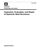
Multiple Drop Impact
The number
of
impinging water drops is critical to the material removal process. The
situation can be generalised by the relationship shown in Fig.
2.9.
This function can
sufficiently be described by
mc(ND)
=
ale
(ND
-
N*,)bl.
(2.25)
The following three regions can be distinguished in Fig.
2.9:
region
I
(ND
<
Nh):
for very
small
numbers of impinging drops, no material
removal occurs: the number of drops is not sufficient to visibly damage the
material. The critical drop number
WD
can be considered to be an incubation
number.
region
I1
(ND
<
WD,
bl
=
1):
a linear relationship with a progress of
41
exists
between drop number and removed material. Any additional drop impact
removes an equivalent mass of material.
region
I11
(ND
<
WD,
0
<
bl<
1):
the progress
of
the function drops, and
al
=
f(ND).
The erosion efficiency declines which can be explained by drop
break-up due to the roughened surface; also, the impact is no longer normal
to the whole of the surface.
region
111
I
Figure
2.9
Drop number influence on mass
loss
(measurements: Baker
et
al
1966).
Fundamentals of Hydroblasting
29
2.3
Parameter Influence on the Coating Removal
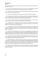
2.3.1
Parameter Definition
2.3.7.1
Target parameters for coating removal
Basic target parameters include coating thickness
(kc),
mass removal
(mc)
and clean-
ing width
(wc).
They are illustrated in Fig. 2.10(a). For the erosion by a stationary
water jet, these parameters are related through the following approximation:
rn,
=
(.rr/4)
.d
.
hc.
pc.
(2.26)
For a given cleaning width, a certain coating mass must be removed to completely
penetrate the coating with a given thickness.
A
maximum mass removal is desired.
The energy efficiency of the cleaning process is given by the specific energy:
Es
=
EJ/rnc.
(2.27)
This parameter should be as low as possible: its physical unit is kJ/kg. The cleaning
rate is the area cleaned in a given time period:
(2.28)
The thicker the coating and the higher its density, the lower the cleaning rate. The
cleaning rate should be maximum: its physical unit is m2/h. Other target parameters
that may focus
on
the surface quality, such as roughness or cleanliness, are not
considered in this paragraph.
2.3.1.2
Process parameters
Process parameters in hydroblasting are shown in Fig. 2.10(b). They can be
subdivided into hydraulic parameters and performance parameters. Hydraulic
(a) Target parameters.
(b)
Process parameters.
-
Figure
2.10
Target and process parameters for hydroblasting.
30
Hydroblasting and Coating
of
Steel Structures
parameters characterise the pump-nozzle-system; they include the following:
0
operating pressure
(p);
0
volumetric flow rate
(Q);
0
nozzle diameter
(&).
Typical relationships between these parameters are described in Section 3.2.3.2 in
Chapter
3.
Performance parameters are more related to the process performance
and incIude the following:
0
stand-off distance
(2);
0
traverse rate
(
vT);
0
impact angle
(4).
The traverse rate covers additional parameters, such as the number of cleaning
steps,
ns,
and the exposure time
tE.
2.3.2
Pump
Pressure
Influence
Figure 2.1 l(a) shows the relationship between pump pressure and coating mass
loss
which can be described mathematically as follows:
This function features three parameters: a threshold pressure
pr,
a progress param-
eter
AI,
and a power exponent
B1.
The threshold pressure has appeared
in
several
experiments (Taylor, 1995; Wu and Kim, 1995; Mabrouki
et
al.,
1998). The mean-
ing of this parameter is iIlustrated in Fig. 2.12 based on high-speed camera images
taken during the removal
of
a
latex-coating from a fibrous substrate. Note from the
left image the complete reflection of the impinging jet from the coating surface;
no
material was removed. This situation counts for
p
<
pp
In the right image material
erosion occurred; the jet completely removed the coating and penetrated the fibrous
substrate. This situation counts forp
>
Pr.
Some typical values for the threshold pres-
sure estimated by numerous authors were bitumen on steel (Schikorr, 1986),
50-120 MPa for epoxy-resins (Mabrouki
et
al.,
1998), 105 MPa for aluminium (Wu
and
Kim,
1995), 120-140 MPa for alkyd coats (Meunier and Lambert, 1998).
190 MPa for adherent rust (Meunier and Lambert, 1998). and about 200 MPa for
inconel (Taylor, 199
5).
For polymer-particle composite coatings, the threshold pres-
sure IinearIy increased
if
PMMA contcnt and hardness, respectively, increased
(Briscoe
et
al
1997). The progress parameter
AI
depended on coating type and
traverse rate. The general trend for the traverse rate was: the lower the traverse rate,
the higher the value for
A,.
The power parameter
B1
depended on the material. For
aluminium the power exponent was about
B1
=
1
for low traverse rates, but
B1
>
1
for higher traverse rates (Wu and Kim. 1995). For paint systems (epoxy-based see
Fig. 2.11(a) and bitumen (Schikorr, 1986)) the exponent tended to
B1<l.
The
curves for these coatings at high pressures confirmed a square-root-model for
Fundamentals
of
Hydroblasting
3
1
.
epoxy-resin coating
-
CB
-A
0)
30;
-
8
20-
E
c
In
In
3
2
10
-
0
"'
I, ,
(b)
Specific energy (Wright
et
a/.,
1997).
0.012
m
E
3
2
0.008
h
a
c
a,
0
0
a,
P
s
0.004
I2
nozzle diameter:
0.5-2.8
mn
traverse rate:
3.3
mlmin
coating: rubber
0
~"""""'~"'''~
0
1FO
200
300
400
500
700
900
1100 1300 1500
Operating pressure in MPa
Operating pressure in bar
(c)
Pit cross section (Mabrouki
et
a/.,
1998).
,.
,'
,:
./I.
,
.
,
,
,
,
, ,
0
100
200
300
Operating pressure in MPa
Figure
2.11
Pressure influence on cleaning parameters.
soft-solid coatings developed by Thomas
et
al.
(1998).
In no case the exponent
reached the value
of
1.94
as suggested by a cleaning model developed by Leu
et
al.
(1998).
If
B,
=
1 (which may be valid
for
high traverse rates as usually applied
for
cleaning processes), the pressure
for
optimum energy consumption can be estimated
from
the following relationship:
For
dE,/drn,
=
Min,
Eq.
(2.28)
delivers
(2.30)
32
Hydroblasting and Coating
of
Steel
Structures
Figure2.12
5
mm:fibrous substrate.
Thresholdconditionsforalatexlayer (WeiJandMomber;
1998);
Zeft:p<h: right:p>h; scale:
For the applications shown in Fig. 2.1 l(a), the energetically optimum pressure
ranged between 150 and 360 MPa for epoxy-resin coatings. The higher value
exceeds already the limit of commercially available hydroblasting systems.
Figure 2.1 l(b) taken from rubber removal experiments, proved the low specific
energy at high pump pressures. Results obtained on epoxy-resin coatings,
Fig. 2.11(c), and
on
aluminium samples
(Wu
and Kim, 1995) showed that the
cleaning width was linearly related to the pump pressure, but the progress was
rather low. The progress of the function was also almost independent of the
traverse rate.
A
threshold pressure could not be noted. There is disparity in the
threshold pressures if Figs. 2.1 l(a) and 2.1 l(c) are compared. From Fig. 2.1 l(c),
threshold pressures would be between
10
and 50 MPa which do not match
Fig. 2.1 l(a).
A
spot may be seen at
p
=
50 MPa at the surface in case of coating
'B',
but still no material is measurably removed.
2.3.3
Nozzle Diameter Influence
The relation between nozzle diameter and mass
loss
is shown in Fig. 2.13(a). It can
be noticed that the function approaches
Eq.
(2.29) with three characteristic param-
eters: a threshold nozzle diameter
dT,
a progress parameter
A2,
and a power exponent
B2.
The threshold diameter was, independently of the traverse rate, at about
dT
=
0.05 mm; this was far from the diameter of commercially applied nozzles. The
progress parameter
A2
increased as traverse rate decreased. For low traverse rates,
the power parameter was
B2
>
1.
Figure 2.13(b) illustrates the influence of the noz-
zle diameter
on
the cleaning width. The relation was equal to that obtained for the
pump pressure.
A
threshold value could not be noted which was due to the same
effect as for the pump pressure.
Fundamentals
of
Hydroblasting
3
3
240
E
t
._
2
m m
VI
u)
120
r"
60
0
(a)
Mass
loss.
(b)
Cleaning
width.
3
m18o:p
1.:
6
g1-
c
-
h.
.
.
Substrate: steel
vT=0.12m/s
Epoxy-resin coating
Coating: epoxy resin
p
=70
MPa
-A
-B
.'"'"".'
0
* '".''.'
C
traverse rate in cdmin
I
v)-
v)
-
0-
2-
30
-
$60-
~ dT
0
I
,
,
,
I
,
, ,
0
0.1
0.2
0.3
0.4
0.3
I
traverse rate in cm/min
+2.54
-157
7
5
o.2
f
coating: ductile
0
0
0.1
0.2
0.3
0.4
Nozzle diameter in mm
Nozzle diameter in mm
Figure
2.13
Influence
of
nozzle diameter on cleaningpurameters
(Wu
and Kim,
1995).
2.3.4
Stand-off
Distance
Influence
Any coating removal target parameter is very sensitive to variations in stand-off
distance. This is illustrated in Figure 2.14. Initially, mass loss increased linearly with
the stand-off distance up to a value of
x
=
270 mm (Fig. 2.14(a)). If this value was
exceeded, the progress dropped.
For
a certain optimum stand-off distance, a maxi-
mum in the material removal could be observed at about
xo
=
300
mm
(xoIdN
=
200).
Similar was the situation with the pit cross section as shown in
Fig.
2.14(b).
This parameter was also sensitive to variations
of
the stand-off distance. Similar
results were reported by Leu
et
al.
(1998) for epoxy-based paints. The optimum
stand-off distance was at about
xo
=
80
mm
(xOIdN
=
260)
for both paint systems in
34
Hydroblasting and Coating
01
Steel
Structures
Fig. 2.14(b). Both xo/dN-values were beyond the jet core (Fig.
2.6)
and pointed to an
influence of dynamic effects, namely drop impact and structural disturbances.
Leu
et
al.
(1998) derived the following relationship between cleaning width and
stand-off distance for a stationary water jet:
w,
=
2
.
c,.
[
1
-
($)72/3.
(2.32)
The spreading coefficient can be taken as
C,
=
0.033 from experimental results. The
critical stand-off distance was given through
(Leu
et
a].,
1998):
(2.33)
Here,
a,
is
the endurance limit
of
the coating material (see Fig. 2.19), andh is a stress
coefficient. From Leu
et
al.'s
(1998) deviation a ratio
h/u,
=
m,-c,
could be
assumed.
2.3.5
Traverse
Rate
Influence
Typical relationships between removed mass and traverse rate for different materials
are shown in Fig. 2.15(a). Mass loss dropped for all materials
as
traverse rate
increased. It could be seen that the mass loss drop was very dramatic for low traverse
rates. The relation is a simple power law
c1
m,
=
-
"T.
(2.34)
The constant
C1
depended on the applied coating system and only slightly on oper-
ating pressure. The situation was different
if
mass loss rate was considered as illus-
trated in Fig 2.15(b). In that case the traverse rate should be rather high to obtain a
high mass loss rate. The certain trend depended on the operating pressure. For
rather low pressures an optimum traverse rate existed. Such an optimum was
observed for the removal
of
soil
films
from brass (Kaye
et
al.,
199
5).
The cleaning rate
also increased as the traverse rate increased (Fig. 2.15(c)) suggesting that quickly
rotating hydroblasting tools are superior to stationary tools.
A
more general relationship for the estimation of the cleaning rate was derived by
Sundaram and Liu
(1
9 78):
(2.35)
Here,
tLT
is a threshold exposure time that
will
be discussed later. Cleaning is zero
both at
vT
=
0
and at
vT
=
wc,,,/t~.
Maximum cleaning rate could be derived by
Fundamentals
of
Hydroblasting
3
5
600
E400
K
8
0
v)
v)
-
r"
200
0
operating pressure in MPa
+75-60
1
-
-
'''''~'''~''''~
(b) Mass
loss
rate (Schikorr, 1986).
substrate: steel
operating pressure in MPa
0
0
50
100
150
Traverse rate in mm/s
(c) Cleaning rate (Babets and Geskin, 1999).
1.2
5
0.9
E
2
0.6
c
a,
c
m
c
K
m
(D
-
0
0.3
0
coating: oil-based paint
substrate: low-carbon steel
0
2
4
6
8 10
Traverse rate in dmin
Figure
2.15
Traverse rate influence on cleaning parameters.
solving dAc/dvT
=
0.
The corresponding traverse rate is given as follows:
0.707
.
wC,,,
G?r
v;
=
(2.36)
Traverse rate actually expresses the local exposure time:
The jet diameter can often
be
replaced
by
the node diameter
(d,
=
dN).
A
plot of local
exposure time versus mass
loss
is
shown in
Fig.
2.16(a); the results were taken from
Fig. 2.15(a) and recalculated with
Eq.
(2.37). Mass
loss
increased dramatically at
low
-75
-60
exposure time: if the local exposure increased further, efficiency (in terms of the
slope
of
the curve) dropped. From this point of view, short local exposure times (high
traverse rates) are recommended. A threshold exposure time could
also
be noted
-
it
was about
0.005
s
for the conditions shown in Fig. 2.16(a). Such a parameter
is
known from other liquid jet applications, namely concrete hydrodemolition
(Momber and Kovacevic,
1994).
hydro-abrasive machining (Momber and
Kovacevic,
1998)
and cavitation erosion (Momber, 2003b).
A
critical traverse rate
exists for most combinations of coating and operating pressure. This critical condi-
tion could also be derived from
Fig.
2.1
5(a): it would be the intersection of the curve
with the abscissa at very high traverse rates. The most probable explanation is that
erosion of the coating starts after
a
period of damage accumulation by subsequently
impinging drops. This aspect is discussed in Section
2.4.
No
threshold limit exists in
Fig. 2.16(b) which was obtained from the removal of rather soft coatings. This
relationship could be described by a simple square-root law (Thomas
et
al.,
1998):
soft
coating removal
Ac
til2,
(2.38)
and this law may apply to any particular coating system (for example to epoxy-based
coatings: Mabrouki
et
ul.,
1998). However, an exponential regression was also suc-
cessfully applied to relate exposure time and cleaning width (Louis
et
al.,
1999).
The
mass
loss
rate
mc
=
Arn,/At,
(2.39)
must have a maximum at rather short relative exposure times (see Fig. 2.16(a)).
After a time of about
0.01
s,
a further increase in the exposure time reduced the
Fundamentals
of
Hydroblasting
37
0.008
m
5
0.006
3
C
=
0.004
a
0
c
0
a
2
0.002
.
.
.
-t
-
33.6 -93.2
mass loss rate. If this optimum exposure time is known, a strategy for multi-pass
stripping can be developed. Simply introduce the optimum exposure time several
times into the duration that corresponds to the desired mass
loss
rate:
n,
=
1.2,3
,
(2.40)
An
example may be calculated based on Fig. 2.16(a). If a mass loss of
mc
=
500
mg
is required to completely penetrate the coating thickness, a local exposure time of
tE
=
0.06
s
is
requested. The optimum exposure time for dmMldtE
=
max is
to
=
0.01
s
which gives
mc(t=to)
=
170
mg. The theoretical step number calculated from
Eq.
(2.40)
is
ns
=
2.94,
in practice
ns
=
3. The entire exposure time required to
remove the desired coating mass is thus
tE
=
0.03
s
which is about
50%
of
the time
for a one-step removal. The gain in efficiency is also
50%.
The relationship between rotational speed and specific energy is shown in
Fig. 2.17. Note that rotational speed and traverse rate were coupled through
Eq.
(2.8).
There was
no
distinct trend. For a rather high pump power
(90
kW
could be
assumed for hydroblasting applications), specific energy was high for low rotational
speeds and approached a lower stable level at higher speeds. The cleaning width had
only a weak relationship to the traverse rate. It slightly decreased
if
the traverse rate
increased (Babets and Geskin, 2001).
2.3.6
Impact
Angle
Influence
Most nozzles in a rotating nozzle carrier
are
angled (see Chapter 3). Typical angles
are between
10"
and
15".
The corresponding impact angles are between
75"
and
80".
The impact angle influence
on
the removal
of
rubber is shown in
Fig.
2.18.
In
the case in question, angled jets improved the cleaning efficiency. However, an
38
Hydroblasting and Coating
of
Steel Structures
coating: rubber
;J
rotational
speed
in min-'
-
-250
-1000
1111111111.I
0.005
m
<
0.004
3
C
2,
0.003
a,
0
!e
0
a,
$
0.002
0.001
20
40
60
80
100
Jet angle in degree
Figure
2.18
Impact
angle
influence (Wright
et
al
1997).
angle variation between
45"
and
60"
did not influence the cleaning efficiency much.
A
perpendicular impact showed worst results from the point of view of energy effi-
ciency.
It
should be noted that these results were valid only for rubber as a highly
deformable material.
2.4
Models
of
Coating Removal Processes
2.4.1 Drop
impact
Model
Springer
(19
76)
developed a coating removal model based on material fatigue due to
high-frequency water drop impact. This model was adapted by Meng
et
al.
(1998)
and applied
to
water jet erosion. In Springer's model, the paint mass removed per sin-
gle drop impact is:
=
73.3
.
10-6-pe
*
d;
*
(u~/R~)~.
(2.41)
From this equation, the removed mass increases as impact stress, drop diameter and
coating material's density increase: and it decreases as coating material's erosion
resistance increases. The erosion resistance parameter
Rc
is given
by
(2.42)
This equation contains some common engineering properties
of
the coating, namely
ultimate strength and Poisson's ratio. The impedance ratio is defined
as
(2.43)
Fundamentals
of
Hydroblasting
39
Table
2.5
Mechanical
properties
of
some
coating
systems
(ACI,
1993;
Springer,
1976).
Material Property
Young's Tensile
Poisson's Ultimate
Endurance
modulus
strain
ratio strength
limit
EMinGPa
E~
vc
uu
in MF'a
u,
in MPa
Epoxy binder
Epoxy polymer
Methacrylate binder
Polyester binder
Polyurethane binder
Acrylic
Epoxy
Polyester
Polyethylene
Polyamide
Polyurethane
0.4-0.8
0.6-1.0
0.7
0.24-0.62
0.3-1.0
2.1
22.1
19.3
2.1
26.2
0.07
30
35
100-200
30
1
50-600
0.20
0.35
0.25
0.20
0.2 5
0.20
14
-
3-8
14
6-1
0
221
395
10
386
45
48
386
4
345
14
Some values for these properties are listed in Tables 2.4 and 2.5. Values for
qsc
are
for most coating materials between
0.7
and
1.
The parameter
bc
is a dimensionless
value related to the material's fatigue behaviour:
The parameters in that equation are illustrated in Fig.
2.19(a).
From that figure,
(2.45)
where
N1
is the life cycle number corresponding to the endurance limit
q.
Values for
the strength parameters of some coating materials are given in Table 2.5. However,
the estimation
of
bc
requires the knowledge of the complete fatigue curve of the
material. The dimensionless value kin
Eq.
(2.42) is the number of stress wave reflec-
tions in the coating during the impact time. Thc parameter
cc
is the average stress
on the coating surface:
(2.46)
40
Hydroblasting and Coating
of
Steel Structures
(a) Definition
of
fatigue parameters (adapted
from
Springer,
1976).
Ni=io*z
log (life cycles)
(b)
Drop impact fatigue curve for a coated
substrate (Conn and
Rudy,
1974).
8
120
&t
2
coating: pimented polyutethane
substrate: epoxy laminate
60
io1
io2
103
io4
io5
io6
Number of impacts
Figure
2.19
Fatigue associated
with
water drop
impact.
Here,
CT,,
is the impact pressure given by
Eq.
(2.22).
Values for
qFC,
I'l
and
rz
are
given in Table
2.4.
Ct
is a parameter related to the coating thickness:
(2.47)
r3
The parameter
r3
is tabulated in Table
2.4,
its value
is
between
1
and
1.5
for most
cases. The number of impacting drops per unit area for a time interval
At
is
(Fig.
2.9):
with
At
=
Azlv,
(2.48)
(2.49)
(z
being the direction
of
traverse jet travel).
2.4.2
Water Jet Cleaning Models
A
number of water jet surface cleaning models have been developed over the years.
They
can
be subdivided as follows:
0
0
0
analytical models
(Leu
et
al.,
1998;
Meng
et
al.,
1998;
Louis
et
al.,
1999);
erosion based models (Conn
et
al.,
1987);
fuzzy-logic based models (Babets and Geskin,
2001);
Fundamentals
of
Hydroblasting
41
e
neural network based models (Babets and Geskin,
1999);
numerical simulations
(De
Botton,
1998;
Mabrouki
et
al.,
2000;
Mabrouki
and Raissi,
2002):
regression models (Kaye
et
al.,
1995;
Thomas
et
al.,
1998).
Information about these models may be obtained from the original papers. Most of
them assumed accumulated drop impact as the principal material removal mode and,
therefore, may relate to the drop impact model introduced in the previous chapter.
Louis
et
al.
(1999)
defined the following three stages of a water jet cleaning process:
(i)
damage accumulation (threshold stage):
(ii)
(iii)
rapid erosion of the upper part of the coating (no interaction with
substrate);
slow erosion of the coating near the substrate.
A
criterion for damage accumulation (threshold condition for beginning coating
removal) was due to the following (Louis
et al.,
1999):
k*.mw.(
pF
*
c,
*
v,
)=1,
b*
2
*
Uu
(2.50)
with
b*
=
13.
The parameter
k*
must be estimated
by
experiments.
A
further inter-
esting assumption was a decrease in the erosion rate if the impinging drops
approach the substrate (stage (iii)). This decrease was modelled due to
(2.51)
(see Fig.
2.10a).
The deceleration exponent
C*
was between
2.3
and
2.9
(Louis
et
a].,
1999).
An analytical model for the direct calculation of paint removal by a water jet was
developed by Meng
et
al.
(1996.1998)
and
Leu
et
al.
(1998).
The analysis led to the
following equation for estimating the mass of removed paint per unit area (Meng
et
al.,
1998):
0.Sn+0.5
a
tT)
.
(&rn+2.
(2.52)
From that equation, mass loss increases as pump pressure and nozzle diameter
increases. It drops with an increase in traverse rate and stand-off distance, respec-
tively.
For
the empirical parameter in that equation, the authors found
n
=
2.875
which delivers
mc
tc
p1.94.
It was, however, shown in Section
2.3.2
that experimen-
tally estimated exponents are notably lower. Therefore, the model seems to be valid
for rather low operating pressures. The nozzle exponent
(2
*
n
+
2
=
7.75)
was also
unusually high (compare Fig.
2.1
3(a)).
42
Hydrublasting and Coating
of
Steel Structures
Conn
et
ul.
(198
7)
defined an ‘area cleaning effectiveness’ which was actually the
ratio between area cleaning rate and jet power:
Ac
PJ
e,
=
-
(2.53)
These authors then applied Thiruvengadam’s
(1967)
concept of erosion strength
which yielded
(2.54)
where
I,
was an erosion intensity (defined for hydroblasting applications through a
given nozzle and a fixed set of operational parameters). The parameter
Sc
was
denoted erosion strength (originally defined for metals) and was in
Thiruvengadam’s
(1967)
original work related to the elastic strain energy density.
Strain energy density is known to be a characteristic resistance parameter in other
erosion situations, namely hydro-abrasive erosion (Momber, 2003d) and cavitation
erosion (Momber, 2000d). Equation
(2.54)
is plotted in a log-log graph in Fig. 2.20.
A
definite relationship between
e,.,
and
Sc
can be seen. The values for the erosion
strength for cleaning similar materials are closely spaced together, and conse-
quently
S,
can be used to characterise an unknown paint-substratc combination as
far as operational conditions
(Ir
in
Eq.
(2.54)
or operating pressure in Fig.
2.20,
respectively) are comparable. For a given material group (such as epoxy paint
or
IO’
102
1 03
104
Erosion strength (relative units)
Figure
2.20
Graphical solution
of
Eq.
(2.54)
for
dilferent materials (values taken from Babets and Geskin,
2001).
Fundamentals
of
Hydrobiasting
43
rust, respectively, in Fig. 2.20) the weaker material exhibits lower values for
S,.
It
may, however, be noted that Sc is a relative value only, and some standard for its
exact experimental estimation is missing. The estimated values for the erosion
strength are listed in Table 2.6.
Zublin
(1983)
developed a model for the cleaning of oil wells. The model basically
related the cleaning speed (equal to the traverse rate
of
the cleaning tool) to a mate-
rial parameter 'Cleaning Energy Flux'
(CE):
The higher values for
CE
the higher the resistance of the materials against water jet
erosion. Values for several materials typically found in oil wells were estimated
by
Zublin
(1983);
they are listed inTable 2.7.
Briscoe
et
ul.
(1995)
defined a parameter
a*
in order to describe the response of
a
deposit (polyethylene glycol)
to
the erosion by hydrodynamic flows. This
parameter characterised the ratio
of
interfacial fracture energy to deposit bulk
fracture energy:
(2.56)
with
TI
being the interfacial fracture energy (see Table 5.20);
EM
and
HM
are Young's
modulus and micro-hardness, respectively, of the coating material. The validity of
this relationship was studied at a phenomenological level only. However, it was found
Table
2.6
Erosion strengths
for
various materials
and
conditions.
Paint /deposit Erosion strength (relative')
Babets and Geskin (2001)
Hard epoxy paint
Weak epoxy paint
Rust from steel
Weaker rust from steel
Auto paint
Oil based paint
Conn
et
al.
(
198
7)
1000'
665
400
3 60
180
30
Steel profiling
1000'
Faint
on
steel 6.2
Paint
on
steel (submerged) 0.65
Antifouling
on
steel (submerged) 0.09
Heavy fouling (barnacles)
on
bronze
Slime, filmy growth
on
bronze
Biochemical contaminant on steel
0.00008
0.019
0.005
'
Nole
the
different standard conditions.
44
Hgdroblusting
and
Coating
of
Steel Structures
Table
2.7
CE-values
for
certain
contaminants
in
oil
wells
(Zublin,
1983).
Material mvalue'
Barium sulphate
Silicates
Calcium carbonate
Calcium sulphate
Carbonate-sulphate-silica complexes
Water scales and hydrocarbon complexes
Coal tar
Coke with
or
without complexes
Wax
with
or
without complexes
Paraffins
Sludges
Thixotrophic materials (mud)
Non-thixotropic materials
7000
6000
5500
4500
3800
3200
3000
2
500
2000
1200
1000
800
500
'Originally
given
in lb
*
fthZ (can also
be
used as relative value).
that the water concentration
in
the eroding fluid
was
critical
to
a*.
If
the concentration
was rather high,
a*
increased and cohesive failure occurred in the bulk
of
the
coating. For
a
low
concentration the erosion mechanism changed, with the coating
breaking into several large fragments. This coating detachment was due to interfa-
cial delamination (Briscoe
et
al.,
1995).
CHAPTER
3
Hydroblasting
Equipment
3.1
High-pressure Water Jet Machines
3.2
Pressure Generator
3.1.1
General Structure
3.2.1
Water Supply
3.2.2
General Structure of High-pressure Pumps
3.2.3
Pump Performance
3.3
High-pressure Hoses and Fittings
3.3.1
General Structure
3.3.2
3.4.1
General Structure and Subdivision
3.4.2
Jet Reaction Force
3.5.1
Rotating Lead-Throughs
3.5.2
Self-Propelling Nozzle Carriers
3.5.3
Externally Driven Nozzle Carriers
3.6.1
Nozzle Types and Wear
3.6.2
Optimisation
of
Nozzle
Arrangements
3.7
Vacuuming and Water Treatment Systems
3.7.1
Vacuuming and Suction Devices
3.7.2
Water Treatment Systems
Pressure Losses
in
Hose Lines
3.4
Hydroblasting
Tools
3.5
Nozzle Carriers
3.6
Hydroblasting Nozzles
46
Hydroblasting and Coating
of
Steel
Structures
3.1
High-pressure Water Jet Machines
3.1.1
General
Structure
3.1.1.1 Definition
of
high-pressure
water
jet machines
For on-site applications, high-pressure water jet machines are well established.
According to the
DIN
EN
1829,
high-pressure water jet machines are defined correctly
as follows: ‘Machines with nozzles or other speed-increasing openings which allow
water
-
also
with admixtures
-
to emerge
as
a
free jet.’
3.7.
7
.2
Basic components and subdivision
High-pressure water jet machines consist of the following major parts:
0
drive;
0
pressure generator;
0
hose lines;
0
spraying devices:
0
safety mechanisms;
0
control and measurement devices.
Mobile high-pressure water jet machines are readily transportable machines
which are designed to be used at various sites, and for this purpose are generally fit-
ted with their own undergear or are vehicle mounted, all necessary supply lines
being flexible and readily disconnectable. Stationary high-pressure water jet
machines
are
machines designed to be used at one site for a certain period of time
but capable of being moved to another site with suitable equipment. They are gen-
erally skid or base frame mounted with supply lines capable of being disconnected.
Major parts of high-pressure water jet machines are shown in Fig.
3.1.
They include
base frame, fuel tank, driving engine, couplings, high-pressure plunger pump, filter,
header tank, booster pump and valves.
3.
I.
7.3 Drives
The type of drive depends
on
the conditions of use. For hydroblasting applica-
tions, possible drives include electric motors and combustion engines. Under
outdoor conditions, diesel combustion engines are most commonly used: typi-
cal power ratings are between
80
and
200
kW.
These engines drive the high-
pressure pumps as well as any auxiliary energy consumers, such as required
centrifugal pumps, compressors or high-pressure tools. Many of the engines
connected to plunger pumps will run at a fixed speed (see Table
3.4).
However,
gear boxes, placed between drive and pump drive shaft, can be used to vary the
speed of the crankshaft.
Hydroblasting
Equipment
47
(a) Mobile unit (WOMA GmbH, Duisburg). (b) Double pump system (Muhlhan Surface
Protection lntl GmbH, Hamburg).
PI
,I
-
(c) On-board unit (Hammelmann GmbH, Oelde).
(d) Containerised unit (Hammelmann GmbH, Oelde)
F-’
-3
<-
Figure
3.1
Structures
of
hydroblasting machines.
3.2
Pressure Generator
3.2.1
Water
Supply
For running high-pressure plunger pumps reliably and for achieving a maximum
service life, pump manufacturers recommend drinking water quality. SSPC-SP
12/NACE No.
5
defines standard jetting water as follows: ‘Water of sufficient purity
and quality that it does not impose additional contaminants on the surface being
cleaned and does not contain sediments or other impurities that are destructive to
the proper functioning of waterjetting equipment.’ But if suitable filter and cleaning
arrangements are applied, even river water or seawater can be used. Recommended
filter size depends on the sealing system as well as on the operating pressure. Typical
sizes are listed in Table
3.1.
All water filter arrangements are dependent upon the
supply water conditions, and they should be checked at regular intervals, usually
not exceeding
8
h.
Usually, especially for high-power pumps, the inlet water must enter the
pump under a certain required inlet pressure. Typical values for the inlet pres-
sure are between
0.3
and
0.5
MPa. The inlet pressure is usually generated by