Hydroblasting and Coating of Steel Structures 2011 Part 4 potx
Bạn đang xem bản rút gọn của tài liệu. Xem và tải ngay bản đầy đủ của tài liệu tại đây (562.77 KB, 20 trang )
48
HHdroblasting
and
Coating
of
Steel
Structures
Table 3.1
Operating
pressure
in MPa
Recommended water filter
siaes
(Kauw, 1992).
Recommended filter
size
in
pn
<loo
100
100-200
10
>200
Manufacturer recommendation
Table 3.2 Recommended water quality for plunger pumps and drinking water quality
(WOMA Apparatebau GmbH, Duisburg).
Parameterlelement Permissible value Drinking water analysis'
Temperature
30°C
10-14'C
pH-value Depends on carbon hardness 7.45-7.7
Hardness
3O-30"
D.H.2
22.5"-27.5" D.H?
Fe 0.2 mg/l
0.2
mg/I
Mn
0.05
mg/l
0.02
mg/l
c1
100
mg/l
48-58
mg/l
KMn04 12 mg/l
-
so4
Solved oxygen min. 5 mg/l
-
Abrasive particles 5 mg/l
-
100
mg/l 140-205 mg/l
-
Clz
0.5
mg/l
Conductivity
1000
pSlcm
700-900 pS/cm
'
Water
works
Duisburg.
D.H. =German hardness.
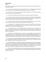
centrifugal booster pumps that are part of commercial hydroblasting systems. For
some pump types, header tanks located on a higher level than the suction pipe are
sufficient.
In order to achieve optimum and reliable pump performance, pump manufacturers
recommend drinking water quality.
SSPC-SP
12INACE
No.
5
states the following: 'The
cleaner the water, the longer the service life of the waterjetting equipment.' More
detailed requirements are listed
in
Table
3.2.
3.2.2
General
Structure
of High-pressure
Pumps
3.2.2.7
subdivision and basic components
High-pressure pumps generate the operating pressure and supply water
to
the spraying
device. Generally, they can be divided into positive displacement pumps and hydraulic
intensifiers. Positive displacement pumps
are
standard for hydroblasting applications.
In Germany, almost
90%
of all on-site devices are driven by positive displacement
pumps. The most common form is a triplex (three plunger) pump as shown
in
Fig.
3.3.
Major parts of a positive displacement pump are:
0
crank-shaft:
0
0
high-pressure plunger conversion set:
pump head with low-pressure inlet valves and high-pressure outlet valves:
Hydroblasting Equipment
49
3
Solid
amount
in
water
in
mg/l
Figure
3.2
Solid content in water and maintenance costforplunger
pumps
(Reliance Hydrotec Ltd.,
UK).
Table
3.3
Typical
lifetime values for
plunger pump components
(Xue
et
al.,
1996).
Pressure in MPa Component lifetime
in
h
Plunger
Seal
Valve
<30
2
500
1500 3000
20-31.5
2000
1000
2500
31.5-50
1500
750
2000
50-70
1000
600
1500
70b100
800
520
1000
0
pressure regulator valves:
0
switch valves:
0
safety devices.
Lifetimes
of
pump components depend on many parameters, namely water quality
(see Table 3.2). maintenance regime and operating pressure (see Table 3.3). Most
critical to wear and lifetime is the solid amount in water: this is illustrated in Fig. 3.2.
If
solid content increases (e.g. due
to
an insufficient water filter system) cost for
replacement parts (valve seats, seals, plungers) increases.
3.2.2.2
Pump
head and conversion set
Figure 3.3(b) provides a frontal
look
at a pump head. The pump head hosts the water
inlet
and
water outlet valve arrangements. It consists normally
of
corrosive-resistant
forged steel, partly also of coated spheroidal graphite cast iron. Typical plunger diam-
eters for on-site high-pressure plunger pumps utilised for hydroblasting applications
are between 12 and 22
mm.
The plungers are made from coated steel alloys, hard
metals
or
ceramics (the latter material is limited to rather low operating pressures).
50
Hydroblasting and Coating
of
Steel Structures
(a) General structure (M+T
Druckwassertechnik GmbH).
,
(b) Containerised high-pressure
plunger pump (WOMA Apparatebau
GmbH, Duisburg).
Figure
3.3
High-pressure plunger triplex pump.
1.
Pump head;
2,
Pressure valve;
3,
Suction valve;
4,
Inlet
champer;
5,
Plunger;
6.
Gear housing;
7,
Crankshaft;
8,
Connecting rod;
9,
Cross head;
10,
Primary shaft.
3.2.2.3 Safety and control devices
Safety and control devices include safety devices and pressure-measuring devices.
Safety devices prevent the permissible pressure from being exceeded by more than
2.0MPa or 15%. These devices include pressure relief valves or burst disks, respec-
tively. Automatic pressure regulating valves limit the pressure at which the pump
operates by releasing a proportion of the generated volumetric flow rate back to the
pump suction chamber or to waste. It should be used to regulate the water pressure
from the pump and is individually set for each operator. Pressure-measuring devices
directly measure and display the actual operating pressure. Typical control and safety
valve constructions are shown in Fig.
3.4.
An air-operated discharge valve (see left
section) and a pressure gauge (on top of the pump head) are shown in Fig. 3.3(b).
3.2.3
Pump Performance
3.2.3.1 Performance charts
Plunger pumps can be characterised by performance charts. Pump manufacturers
publish performance tables for any commercial pump type. An example is given in
Table
3.4.
A
chart for a typical hydroblasting pump, based on these values, is plotted
in Fig. 3.5. In such charts, the most important technical parameters of the pumps,
such as power rating, operation pressure, volumetric flow rate, plunger diameter and
crank-shaft speed, are related to each other.
3.2.3.2 Hydraulic pump power and hydraulic efficiency
The theoretical hydraulic power consumed by a plunger pump is
PT
=
0.0166
.
QN
'p.
(3.1)
Here,
p
is the operating pressure in MPa, and
6,
is the nominal volumetric flow rate
in
l/min; the power
PT
is given in
kW.
For a given hydraulic power,
Eq.
(3.1)
is a hyperbolic
Hydroblasting Equipment
5
1
(b) Valve for multiple-consumer
systems.
~-
1_y~_
(a) Safety valve.
(c) Manually operated 2/2-way (d) Pneumatically operated 3/2-way
discharge valve. by-pass valve.
Figure
3.4
Typical control and safety valve constructions (photographs:
WOMA
GmbH, Duisburg).
function
(y
=
dx),
and each hyperbola can be considered as a line
of
constant power.
This is shown in Fig. 3.5 for four different crank-shaft speeds.
In
practice, however, the
consumed power exceeds this theoretical value because of losses due to leakage,
pulsations, water compression and other mechanisms. Thus, hydraulic efficiency is
calculated to evaluate the efficiency of plunger pumps. This hydraulic efficiency is
Values for
qH
depend
on
pump type and operating pressure: they increase as
operating pressure increases; this is illustrated in Fig. 3.6(a). Typically, values
52
Hydroblasting and Coating
of
Steel Structures
300
C
2
3
250
3
v)
P
m
c
c
2
0
200
Table
3.4
Performance table
of
a
commercial high-pressure plunger pump.
'
-
.n,
=
-
Plunger
Gear ratio
Crank-shaft Required
Volumetric
Permissible
diameter Drive
speed
in min-'
speed drive
flow
rate pressure
in
nun
1500 1800
in min-' in
kW
in Vmin
in
MPa
-
nc=331
min-'
15 3.57 504
4.52 398
3.57 420
4.52 331
16 3.57 504
4.52 398
3.57 420
4.52
331
18 3.57 504
4.52 398
3.57 420
4.52 331
120
95
100
78
117
93
98
74
122
96
100
78
22
300
18
19
15
26 250
20
21
17
32 200
26
27
21
350
nc
=
420
min-'
Lo-
d
-15mm
n,
=
504 mid
Db
between
r)H
=
0.8
and
=
0.95
can be considered for the pressure range between
200
and
380
MPa.
State-of-the-art high-pressure plunger pumps are capable of
generating operating pressures up to
p
=
300
MPa. The maximum permissible
operating pressure of a certain pump type depends on the permitted rod force. The
corresponding relationship is
FP
=
(~14)
.
d$
.
p.
(3.3)
Hydroblasting Equipment
53
s
6
80
c
C
0)
0
5
0
3
‘D
A-
I
-
2
60-
40
(a)
Hydraulic efficiency.
-
nozzle
diameters:
0.25/0.30/0.36/0.38
mm
I I
I
I
I
I
’
8
I
I
*
20
100
I
I
Typical rod force values for high-pressure plunger pumps are between
10
and 120
kN.
The overall efficiency of a high-pressure plunger pump can be estimated as follows:
where is the mechanical efficiency (internal frictional losses) and
rlT
is the
efficiency of energy transmission between drive and pump. Results of measurements
are
shown
in Fig. 3.6(b). The overall efficiency ranges from 60% to about 85% and
increases as operating pressure increases. In comparison to overall efficiencies of
60-70%
for hydraulically driven intensifier pumps, these values are higher.
3.2.3.3
Nominal volumetric
flow
rate
The nominal volumetric flow rate delivered by a plunger pump can be approximated
as follows:
(3.5)
Here,
&
is
a
compressibility parameter,
n,
is
the crank-shaft speed,
dp
is the plunger
diam-
eter,
Hs
is
the stroke
and
Np
is
the number of plungers. Typical values for these parame-
ters
are listed in Table 3.5. The crank-shaft speed of a pump drive depends
on
the stroke:
the acceleration of the plunger (of the liquid volume, respectively) should not exceed a
critical value. For most pumps, the following criterion holds (Vauck
and
Miiller, 1994):
n$
*
H~
=
1 2
m/s2.
(3.6)
Equation
(3.5)
is partly graphically illustrated in Fig. 3.5. State-of-the-art
plunger pumps are capable of generating nominal volumetric flow rates up to about
1000
l/min. If the operating pressure increases, compressibility of water becomes
important. Schlatter (1986) performed a regression analysis for various tabulated
54
Hydroblasting and Coating
of
Steel Structures
Table
3.5
Performance parameters
of
plunger pumps
for
hydroblasting applications.
Parameter Performance range
Operating pressure in MPa
Volumetric flow rate in Vmin
Hydraulic power in
kW
Plunger diameter in mm
Crank-shaft speed in min-'
Stroke in mm
Rod force in
kN
100-300
10-60
100-300
12-20
300-500
50-140
10-120
75
"""""""""'
0
200
400
600
800
11
Pressure
in
MPa
00
Figure
3.7
Compressibility
of
water and oil (measurements: Bosch-Rexroth
AG,
Lohr).
results of measurements. His empirical formula originally applies to the density but
is rewritten here for
&:
(3.7)
&'c=
-0.00276
*p2
+
0.04382
'p.
The pressure must be inserted in
lo-'
MPa. For an operating pressure
of
p
=
200
MPa,
for example, the volume difference due
to
water compression is about
7.5%
(&
=
0.08).
Note from Fig.
3.7
that a second-order polynomial reasonably fits experimental
results. However, the compressibility for a pressure
of
p
=
200
MPa is slightly lower
(5%)
in
Fig.
3.7.
Generally, the volumetric flow rate of a plunger pump
is
not a constant value. It
rather oscillates according to a sinus-function:
QN
=
AP
.
v,
.
sin
aC.
(3.8)
Here,
Ap
is the plunger cross section,
vc
is
the circumferential velocity and
ac
is the
angle of the crank-shaft. This relationship is illustrated in Fig.
3.8.
The liquid volume
Hydroblasting Equipment
5
5
110
100
90
80
+
Flow
capacity
in
%
-
6.64%
25.06%
t
-
18.42%
V
+
-
I
I
I
is first accelerated and then decelerated. It can be seen from Eq.
(3.8)
that the
unsteady volumetric flow rate is basically a result of the unsteady circumferential
velocity
of
the crank-shaft. The average plunger speed (which
is
about the average
liquid flow velocity in the pump) is simply given as follows:
See De Santis
(1995)
and Nakaya
et
aZ.
(1983)
for further details.
3.3
High-pressure Hoses and Fittings
3.3.1
General
Sfrucfure
The transport
of
the high-pressure water to the spraying devices occurs through
high-pressure lines. For on-site applications, these are flexible hose-lines. These lines
are actually flexible hoses operationally connected by suitable hose fittings (see
Fig.
3.9).
Hose fittings are component parts or sub-assemblies of a hose line to func-
tionally connect hoses with a line system or with each other. High-pressure hoses are
flexible, tubular semi-finished product designed of one or several layers and inserts.
They consist of an outer cover (polyamide, nylon), a pressure support (specially
treated high-tensile steel wire), and
an
inner core
(POM,
polyamide,
nylon).
Any hose
must be tested
for
bursting: the permissible operating pressure
of
hoses should not
exceed
40%
of the estimated burst pressure. Hoses capable of use for pressures equal
to or higher than the maximum operating pressure of the pressure generating unit
must be selected. The lifetime of high-pressure hoses depends on the operating pres-
sure; this is shown in Fig.
3.10.
Typical nominal lengths
of
high-pressure hoses are
between
ZH
=
3
m and
ZH
=
120
m. Table
3.6
contains typical technical parameters for
hoses used in hydroblasting applications.
56
Hydroblasting and Coating
of
Steel
Structures
Figure 3.9 High-pressure hose with fitting (photograph:
WOMA
GmbH, Duisburg).
s
t,,,l,,,,~,,l,,,,,,,l
2
50
0
20
40
60
80
100
Life
time
in
%
Figure 3.10 Operating pressure and hose
lijietime
(JISHA,
1992).
Table
3.6
Technical data of high-pressure hoses for hydroblasting operations.
~~ ~ ~~
Nominal width Maximum operating Maximum delivery
Specific weight Minimum bend
in
mm
pressure
in
MPa
length in
m
in
kg/m radius in
mm
4 280
5 325
8 210
8 300
10
200
20 140
200
200
200
200
200
200
0.54 200
0.41
150
0.60
200
1.10
250
1.01
2 50
1.82 350
Hgdroblasting
Equipment
5
7
3.3.2
Pressure
Losses
in
Hose
Lines
3.3.2.1
General relationships
A permanent problem with high-pressure hoses is the pressure loss in the hose-lines.
An approach for estimating the pressure
loss
is
(3.10)
Here, is a friction number,
p~
is the water density,
vF
is the flow velocity,
IH
is the
hose length and
dH
is the hose diameter. The flow velocity of the water inside a hose
can be estimated
by
applying the law of continuity:
(3.11)
The friction number depends on the Reynolds-Number, Re, and on the ratio between
hose diameter and relative internal wall roughness,
k:
lF
=
f
Re,-
.
(
3
(3.12a)
This number can be estimated from the so-called Nikuradse-Chart which can be
found
in
standard books on fluid mechanics (e.g. Oertel, 2001).
An
empirical rela-
tionship is
(3.12b)
with
Re
=
vt,
dH/z+.
Eqs. (3.10)-(3.12) deliver:
Ap
cc
ai5.
(3.13)
This equation illuminates the overwhelming influence of the hose diameter on the
pressure
loss.
To
substitute these pressure losses, a certain amount of additional
power
must be generated by the high-pressure pump.
3.3.2.2
Pressure
loss
charts
and
hose
selection
Manufacturers of hydroblasting equipment publish pressure-loss charts or pressure-
loss
tables which can be used for estimating real pressure losses in hoses (see Fig. 3.11
for an example). An empirical rule for selecting the proper hose diameter
is:
the
flow
58
Hydroblasting and Coating
of
Steel Structures
velocity in the hose should not exceed the value
of
vF
=
8
m/s. Based
on
Eq.
(3.1
l),
the corresponding minimum hose diameter is
dH
=
1.63
.
$I2.
(3.15)
In that equation, the volumetric
flow
rate is in l/min, and the hose diameter is in
mm.
If
no
standard diameter
is
available
for
the calculated value, the next larger
diameter should be selected,
As
an example:
for
a volumetric
flow
rate
of
40
l/min,
Eq.
(3.1
5)
delivers
10.3
mm;
the recommended internal hose diameter is
dH
=
11
mm.
Equation
(3.1
5)
is graphically illustrated in Fig.
3.12.
Volumetric
flow
rate
in
I/min
Figure
3.
I1
Pressure lnss~s
in
high-pressure hoses.
16
I
E
5
12
5
c
W
5
38
r
-0
al
F
8
E4
E
W
IT
01
"
'
"
'
"
'
"
'
0
20
40
60
80
Volumetric
flow
rate in Vmin
Figure
3.12
Selection
of
suitable hose diameters.
range
of
low
-
pressure
loss
-
range
of
high
pressure
loss
Hydroblasting Equipment
59
E-
a
>
m-
Figure
Olsen,
/I
/I
0
6
12
18
24
Volumetric flow
rate
in Vmin
Approximated pressure losses in high-pressure fittings (based on measurements
of
1989).
yhuvan and
3.3.2.3
Pressure
loss
in
fittings
The correct pressure losses in hose fittings should be measured for any individual
fitting. However, such values are not available in most cases. The following empirical
approximation can be performed according to the curves plotted
in
Fig.
3.1 3:
the pres-
sure loss in a single fitting is equal to the pressure loss
in
a hose of equal diameter with
a length of
3
m. If, for example, a volumetric
flow
rate of
40
l/min and a hose diam-
eter
of
11
mm
are used, the pressure loss estimated
from
Fig.
3.11
ish
=
0.75
bar/m.
Thus, the pressure
loss
in the fitting is
0.225
MPa.
This
corresponds to a power
loss
of
AP
=
0.15
kW.
For hydroblasting tools and valves, special pressure loss-diagrams are
available.
3.4
Hydroblasting
Tools
3.4.1
General
Sfructure
and
Subdivision
3.4.1.7
Hand-held
tools
A
hand-held hydroblasting tool can be used as long as the jet reaction force does not
increase beyond a value of
FR
=
2
50
N.
For reaction force levels
150
N
<
FR
<
2
50
N,
hand-held guns can only be used with additional body support. The classical tool for
manual hydroblasting applications
is
the high-pressure gun as illustrated in Fig.
3.14.
It consists of hand grip, pressure housing, trigger, control units and nozzle pipe.
The guns can be equipped with different nozzle carriers as discussed in Section
3.5.
Any tool
can
be run with mechanical (valve), electric or pneumatic control, respec-
tively. According to the valve
type,
hand-held tools can further be subdivided
into
dry
shut-off safety valve and dump safety control valve.
Dry
shut-off valves, normally
hand-controlled, automatically shut
off
flow
to the gun when released by the operator,
60
Hydroblasting and Coating
of
Steel Structures
but retain the operating pressure within the supply line when
so
shut off. Dump safety
control valves automatically terminate significant flow to the gun when released by
the operator, thus relieving the operating pressure within the whole system by divert-
ing the flow rate produced by the pump to atmosphere through an orifice and dump
line, which must be of sufficient size. The flow of the high-pressure water through the
gun causes pressure losses. These losses can be estimated from pressure
loss
graphs
provided by manufacturers: an example is shown in Fig.
3.15.
Figure
3.14
Hydroblasting gun with nozzle carriers (photograph: WOMA Apparatebau GmbH, Duisburg).
Volumetric
flow
rate in Vmin
Figure
3.15
Pressure
loss
graph
of
a hydroblasting gun
(WOMA
Apparatebau GmbH, Duisburg).
Hydroblasting Equipment
6
1
(a) Hand-held wall cleaning tool
(Hammelmann GmbH, Oelde).
(b)
Floor
cleaning
tool
(WOMA GmbH,
Duisburg).
(c) Mechanically guided
tool
(Hamrnelmann GmbH. Oeldel
(d) Self-adhering, mechanised
tool
(WOMA
GmbH, Duisburg).
Figure
3.
I6
Emission-free performing hydroblusting
tools.
A
special hand-held hydroblasting tool for emission-free surface preparation
applications is shown in Fig. 3.16(a). These tools are equipped with sealing systems
consisting of brushes or, in case of very high sealing demands, of sealing lips.
Typical technical parameters for two tool types
-
for floor cleaning and for wall
cleaning
-
are listed in Table 3.7.
3.4.1.2
Mechanised
tools
Mechanised hydroblasting tools are usually applied for large-scale applications, such
as ship hulls or large storage tanks. Most of these tools are also equipped with sealing
systems and perform emission-free. Mechanised tools often comprise more than one
nozzle carrier and are, therefore, more efficient than hand-held tools. The simplest
way to use this type of tools is to mount it at conventional guiding/lifting systems,
such as cherry pickers or mechanical platforms. Such an application is illustrated in
Fig. 3.16(c). More advanced tools are self-adhering and self-climbing.
A
typical
hydroblasting tool designed for automatic applications is shown in Fig. 3.16(d);
62
Hydroblasting and Coating
of
Steel Structures
it comprises a pneumatically driven rotating nozzle carrier. Typical technical
parameters of this tool are listed
in
Table
3.8.
As
for hand-held tools, this
unit
can
fully be sealed to prevent any emission of water vapour or dust. This tool can be
connected to vacuuming systems. Recent reviews about mobile blasting tools are
provided by Goldie (1999,2002).
3.4.2
jet
Reaction
Force
The border between hand-held and mechanised tools is set by the permissible
reaction force generated by a water jet. In Europe regulations exist which forbid the
application of hand-held devices
if
the axial component of the reaction force exceeds
the critical value of
FK
=
250
N
(25
kg).
In the
FR
range of
150
and
250
N,
hand-
held guns are allowed, but they need to be reinforced by body support
or
by a second
hand grip. These relationships are illustrated in Fig.
3.1
7
which also shows critical
Table
3.7
Technical parameters
of
emission-free performing hydroblasting
tools.
Parameter Water jetting tool
ETRC'
Vacujet'*2 Lizard't3
Maximum operating pressure in MPa
2
10
250 200
Maximum volumetric
flow
rate in Vmin 20 20
40
Maximum rotational
speed
rnin-l 2500 2 500 2
500
Weight
in
kg 9.2 ca. 36 ca. 55
Working width
in
mm
180
ca. 225 ca.
380
Number
of
nozzles up to
4
up
to
8 up to
10
'
Trade names WOMA Apparatebau GmbH, Duisburg.
SeeFig. 3.16(b).
See
Fig. 3.16(d).
Table
3.8
Mechanised hydroblasting
tools
(Goldie,
1999).
Model' Hydrocat Dockmaster* Hydro-Crawler Spin-Jet
Headsizeinmm 830X625X370 1400X1100X290 965X940X635 686X 762x480
Head weight in
kg
80
247
79
Maximum
pressure
2 75
2
50
2 76 280
Maximum
flow
rate 24
85 53 42
Traverse rate in 6
-
C3.65 6
Cleaning width
300
750 475 2
50
Cleaning rate
<loo
150-300
<SO
<90
-
in MPa
in llmin
mhin
in
mm
in m2/h
Models are trade names
of
manufacturers.
See Fig. 3.16(c).
Hydroblasting Equipment
63
150
Operating pressure in MPa:
300
250
200
hand-held gun operation
without restriction
0
10
20
30
Volumetric flow rate in Wmin
Figure
3.17
Critical conditions/or hand-held gun operation (see
Eq.
(3.16))
combinations of operating pressure and volumetric flow rate. An average rule says
that an operator may be capable of holding about one-third of his body weight
(Summers,
1991).
For example: an operator with a
body
weight of
75
kg could resist
a reaction force
of
FR
=
2
50
N.
The reaction force of a water jet can be estimated through impulse flow
conservation:
Ij
=
lirw
.
vj
=
0.743
QN
*
P”~
=
F
R’
(3.16)
Here,
I,
is
the jet impulse flow,
mw
is the water mass flow rate, and
vJ
is the jet
velocity. In the right term
of
Eq.
(3.16),
p
is in MPa,
0,
is in l/min, and
FR
is in
N.
It
can be seen that the reaction force is critically related to the volumetric flow rate
(and thus to the nozzle orifice cross section). Selected results are plotted in
Fig.
3.1
7.
3.5
Nozzle
Carriers
3.5.1
Rotating Lead-Throughs
A
basic part
of
any rotating nude carrier is a lead-through. This construction
enables the flow
of
high-pressure water through rotating parts. The permissible
rotational speed can be as high as several thousands revolutions per minute. An
operational problem with rotating nozzle carriers is the water volume loss as the
high-pressure water passes the lead-through. This loss depends
on
the operating
pressure and can be approximated with the following equation:
(3.1
7)
112
QL
=
61.
.
P
.
64
Hydroblasting and Coating of Steel Structures
Here, the volumetric flow rate is
in
I/min, and the operating pressure is in ma. The
constant has
an
approximate value of
tL
=
0.47
for operating pressures up to 120 MPa.
The rate the water jet traverses at over the surface is a function
of
the rotational speed
of the nozzle carriers:
vT
=
wT
r,.
(3.18)
Here,
wN
is the rotational speed and
R,
is the radial distance between rotational
centre and nozzle location. Typical values for rotational speeds are listed in Table
3.7.
3.5.2
Self-Propelling Nozzle Carriers
Self-propelling rotating nozzle carrier heads (Fig. 3.18(a)) are usually applied for
hand-held jetting guns. The driving force is supplied by a radial component of the jet
(a) Self-propelling (Harnmelmann GmbH, Oelde).
I
(b) Externally (pneumatically) driven
(WOMA
GmbH, Duisburg).
1
1
t
Figure
3.18
Rotating nozzle carriers for hydroblasting applications.
Hydrublustiny Equipment
65
reaction force:
Fi
=
sin
8,
.
FR.
(3.19)
According to
Eq.
(3.16) the driving force
-
and thus the rotational speed
-
is related
linearly to the volumetric flow rate, and has a square-root relationship with the
operational pressure. Equation (3.19) shows also that rotational speed
-
and thus
the exposure time of the exiting water jet
-
cannot be varied independently of volu-
metric flow rate (nozzle diameter, respectively) and operational pressure. Therefore,
the performance
of
self-propelling rotating nozzle carrier heads can hardly be opti-
mised. On the other hand, no additional energy and no additional lines or hoses are
required for driving them. A typical performance chart of a self-propelling rotating
nozzle carrier is shown in Fig. 3.19(a).
3.5.3
Externally Driven Nozzle Carriers
Externally driven rotating nozzle carrier heads are driven by separate mechanisms.
Hydraulic and mechanical drives can be found usually in mechanised tools or in
stationary systems fed by plunger pumps with comparatively high values of
hydraulic power. They are very efficient for driving large hydroblasting tools.
Pneumatic drives are used for hand-held cleaning tools as well as for on-site
abrasive water jet cutting systems.
A
typical pneumatic drive device
is
shown in
Fig. 3.18(b).
For externally driven nozzle carrier heads, rotational speed, operational pressure
and volumetric flow rate can be varied independently from each other: this is illus-
trated in Fig. 3.19(b). Additional energy is required to drive external nozzle carriers:
a
typical value for a pneumatically driven carrier is
0.09
kW
which is a negligible
part of the overall hydraulic energy
(a) Self-propelling.
4500
c
7
k
3600
E
0
30
60
90
120
Operating pressure in MPa
(b)
Externally driven (pneumatic air).
5000
7
7,
4000
E
4
0
2.5
3
3.5
Volumetric air
flow
rate
in
Wmin
Figure
3.7
9
Performance charts
of
rotating nozzle carriers.
66
Hydroblasting and Coating
of
Steel Structures
3.6
Hydroblasting
Nozzles
3.6.1
Nozzle Types and Wear
3.6.7.1
Nozzle
types
The water jet nozzle (sometimes called orifice) is an extremely important component
of any hydroblasting machine. In the nozzle, the potential energy of the incoming
pressurised water is transformed into the kinetic energy of the exiting high-speed
water jet. Various nozzle types are known, usually designed for certain applications;
this includes the following types:
pipe cleaning nozzles for operating pressures up to 2 50 MPa with several orifices,
directed sidewards or backwards, for tube bundle cleaning;
pipe cleaning nozzles for operating pressures up to 140 MPa for cleaning
large-diameter pipes:
whirl jet nozzles for operating pressures up to 75 MPa for cleaning partially or
fully blocked tube bundles;
round jet nozzles with continuous flow channel for operating pressures up to
200 MPa;
round jet nozzles with sapphire inserts for operating pressures up to 350 MPa;
fan jet nozzles for operating pressures up to 200 MPa;
injection nozzles for operating pressures up to 400 bar for the formation of
hydro-abrasive water jets.
Depending on the nozzle design, one can distinguish between continuous nozzles
and discontinuous nozzles. In the operational pressure range up to
p
=
100
MPa,
continuous nozzles are most commonly used. They are conically designed and made
from hardened steel. For ultra-high pressure applications, because of the comparatively
low volumetric flow rates, the discontinuous nozzles are becoming increasingly used.
They are characterised by a sapphire-made insert (see Figs. 3.20 and 3.22(a)). Nozzle
performance strongly depends on upstream conditions. This is illustrated in Fig. 3.2
1.
1
I
-
I
Figure
3.20
Typical hydroblasting nozzle (photograph: Wasserstrahllabor Hannover).
1,
Sapphire inlet:
2,
Nozzle holder:
3,
Flow
stabilizer:
Hydroblasting Equipment
67
0""""""'"'
0
40
80 120
160
Volumetric flow rate in Ihin
Figure
3.21
Influence
of
upstream conditions
on
nozzle performance (measurements: Wright
et
al.,
1999).
(a) New nozzle
(dN
=0.28
mm).
(b)
Broken insert
(dN
=
0.25
mm).
(c) Increased diameter and edge chipping
(dN
=
0.25
mm).
(d) Broken edge
(dN
=0.30
mm).
i
Figure
3.22
Characteristic wear types
in
hydroblasting sapphire nozzles.