Industrial Control Wiring Guide 2 2010 Part 5 potx
Bạn đang xem bản rút gọn của tài liệu. Xem và tải ngay bản đầy đủ của tài liệu tại đây (110.84 KB, 10 trang )
4. SOLDERING AND TERMINATION
4.5. Crimped joints
The majority of wire terminations used in control
panel assembly are made with crimp connectors. The
main reason for this is that they are easy and quick to
produce.
Crimping simply means that the conductor is placed
into a special crimp connector which is then com-
pressed around it with the use of a crimping tool. See
Section 4.5.2.
4.5.1. Crimp connectors
The crimp fitting end of the connector has a wire
barrel of a suitable diameter to take the conductor. It is
this part that is compressed by the crimp tool.
᭹ The wire barrel may be open.
᭹ Or closed.
᭹ It may be insulated.
᭹ The conductor should be a snug fit in the
barrel.
34
4. SOLDERING AND TERMINATION
The actual connector can have any one of a wide
variety of shapes determined by the requirements of
the job.
᭹ Here are some commonly used single wire crimp
connectors. All are insulated in these examples.
4.5.2. Crimping tools
The purpose of the crimp tool is to correctly apply
pressure to the wire barrel to trap the conductor tightly
so that it cannot be pulled out under normal circum-
stances. At the same time it must not be so tight as to
cause strands or the connector to break.
Crimping tools may be operated in various ways
dependent not only on the size of the conductor but
sometimes on the total number of crimps that will be
needed. However, they are all similar in operation.
᭹ Hand-operated. Used for light duty work –
smaller conductors and small quantities. These
are described here in detail.
᭹ Power-operated. These can be powered by com-
pressed air, electric or hydraulics. Generally they
are bench-mounted but there are hand-held
types.
Manufacturer’s instructions should be followed
carefully.
SAFETY!
Take care when using power crimpers. Guards
should be fitted.
35
4. SOLDERING AND TERMINATION
4.5.3. Hand tools
There are basically two parts to the crimping tool.
᭹ The jaws which are special to the type of
connector and which are often changeable.
᭹ The handles which are usually colour coded for
identification.
᭹ On more expensive tools a ratchet is fitted which
stops them opening until the joint is completed.
Those on simpler types do not and therefore
require more care in use.
᭹ Jaws may be removable to accommodate a range
of wire sizes and connector types. If they are not
then it is normal to colour code the handles to
avoid confusion on a production line.
᭹ The shape of the jaws determines the shape of the
crimp. The jaws therefore are special to a
particular type of crimp connector and will only
give a correctly terminated joint with the appro-
priate parts.
᭹ In this typical example the jaws are held in by the
two screws A and B.
Operation
The actual detail of using crimp tools varies with the
type of crimper you are using. However, there are
some general points worthy of note.
᭹ The wire barrel of the crimp connector is placed
centrally in the jaws and the handles are
squeezed together.
᭹ Once the crimp has been made the jaws are
locked in position by the ratchet. To release the
jaws you squeeze the handles still further. The
jaws will open and the joint may then be
removed.
36
4. SOLDERING AND TERMINATION
᭹ Where no ratchet is fitted you have to gauge how
hard to squeeze the handles to obtain a good
crimp. This is learned by experience and has to
be found by trial and error.
᭹ Some have a locating marker – in this case a
spigot – to ensure the correct location of the
connector.
SAFETY!
When using a hand tool which has a ratchet
mechanism in the handle, take care not to trap a
finger as the operating cycle of the tool is not
reversible. In other words, once the handles are
squeezed together the jaws can only be opened
by applying further pressure to the handles.
4.5.4. Bootlace ferrules
These are special connectors used extensively for
terminating wires to be connected to screw terminals
such as those found on relays and contactors.
᭹ They come in several sizes, with each size
having a different colour.
᭹ Uninsulated versions are also available.
37
4. SOLDERING AND TERMINATION
᭹ The shroud is colour-coded to show the recom-
mended conductor size to be used.
᭹ Always use the correct size ferrule for the wire
you are using.
᭹ Strip the wire so that the conductor will go all the
way through the barrel.
᭹ The insulation on insulated wire fits into the
shroud.
᭹ Place the ferrule into the crimp tool jaws and
clamp it lightly by squeezing the handles a small
amount.
᭹ Push the wire all the way in so that the insulation
butts against the inside of the plastic shroud.
᭹ Crimp the joint by further squeezing the handles.
The tool will lock when the joint is complete,
release by squeezing the handles once more.
᭹ Trim off the excess conductor.
38
4. SOLDERING AND TERMINATION
4.5.5. Insulated eyelets and spades
᭹ These are used to terminate wires which will be
fixed under a screw.
᭹ They are also colour coded by wire size.
᭹ Strip the wire to give the correct amount of
exposed conductor.
᭹ Place the connector into the crimp tool and clamp
it lightly.
᭹ Push the wire into the connector until the
insulation butts against the barrel.
᭹ Crimp the joint as before.
4.5.6. Inspection
Most blind connectors will have some way of
inspecting the wire after crimping.
᭹ This may be a hole – found in multipole inserts.
The wire strands must be visible through the
hole.
᭹ On others like the insulated eyelets, the con-
ductor should protrude through the barrel so that
it is level with the connector insulation.
39
4. SOLDERING AND TERMINATION
᭹ The connector must be free from splits and
flashes.
᭹ The crimp must be on the correct position to
ensure maximum strength to the joint.
᭹ All the strands must be inside the joint.
There are a number of different makes and types
of crimping tools. All connector makers produce
a matching crimp tool for their connectors. It is
essential to use the correct tool for the job.
4.6. Screw clamp terminals
These are the terminals fitted to a wide range of
component types from contactors to switches.
Although the detail design varies, there are a number
of common features.
᭹ All have a captive wire clamp washer.
᭹ Only two wires to each connector.
᭹ Stranded wire ends must be twisted before
fitting.
᭹ It is preferable to use bootlace ferrules to
terminate wires.
40
4. SOLDERING AND TERMINATION
4.7. Terminating coaxial cable
4.7.1. Stripping
The recommended method is to use one of the coaxial
cable strippers currently available. The operating
instructions vary according to type.
᭹ With this tool the cable is passed through the
hole after lifting the top half to open up the
cutter.
᭹ Push the top down to cut the insulation then
rotate to cut it all the way round.
᭹ Pull off the stripper and the insulation stub.
Another way using a sharp knife and wire cutters:
᭹ Rest the cable on the workbench.
᭹ The outer cover can be stripped back using a
sharp knife to make a slit along its length.
᭹ Take care not to damage the inner screening.
᭹ Peel the cover back and trim off with side
cutters.
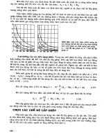
4.7.2. Making a ‘pigtail’
᭹ This is a way of separating the braid and
inner conductor before making any solder
connections.
᭹ The braiding must not be soldered while it is still
on the central insulation.
᭹ Strip about 50 mm off the outer insulation.
41
4. SOLDERING AND TERMINATION
᭹ Push back the braiding to loosen up the mesh.
᭹ Without cutting the braid, use a small screw-
driver to tease a hole in it.
᭹ Lever the central conductor out through the
hole.
᭹ Stretch the braid out and trim off to remove any
loose strands.
᭹ The inner wire may now be stripped in the
normal way.
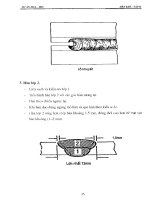
4.7.3. Making an insulated pigtail
᭹ Twist and trim off the braiding to about 15 mm.
᭹ Prepare a length of stranded wire, for example
7/0.2 mm or 16/0.2 mm. Strip the end about
12 mm; twist but do not tin.
42
4. SOLDERING AND TERMINATION
᭹ Twist the braiding and wire together.
᭹ Solder the joint and trim off to 8mm long.
᭹ Fold the connection back over the outer cover.
᭹ Fit a silicone rubber sleeve to cover the joint.
4.7.4. Fitting a BNC coaxial plug
To terminate coaxial cable with a standard BNC
plug:
᭹ Strip off sufficient length of the outer cover and
cut off the braid level with the new end of the
outer cover.
᭹ Fit the gland nut and plastic compression washer
over the outer covering.
43