Nuclear Power Control, Reliability and Human Factors Part 5 pdf
Bạn đang xem bản rút gọn của tài liệu. Xem và tải ngay bản đầy đủ của tài liệu tại đây (1.86 MB, 30 trang )
An Approach to Autonomous Control for Space Nuclear Power Systems
109
intelligent control capability of the functional layer. The decision layer provides
functionality to break down goals into objectives, establish a sequential task ordering based
on the plant/system state and known constraints, and assess the capability of the functional
layer to implement those commands. At lower granularity within the decision layer,
executive functions such as procedure enforcement are dominant while, at higher
granularity, planning functions such as goal determination and strategy development are
dominant.
There is an architectural approach for nearly autonomous control systems that have been
applied through simulated nuclear power applications (see Fig. 1). As part of research into
advanced multi-modular nuclear reactor concepts, such as the International Reactor
Innovative and Secure (IRIS) and the ALMR, a supervisory control system architecture was
devised (Wood et al., 2004). This approach provides a framework for autonomous control
while supporting a high-level interface with operations staff, who can act as plant
supervisors. The final authority for decisions and goal setting remains with the human, but
the control system assumes expanded responsibilities for normal control action, abnormal
event response, and system fault tolerance. The autonomous control framework allows
integration of controllers and diagnostics at the subsystem level with command and
decision modules at higher levels.
Fig. 1. Supervisory control architecture for multi-modular nuclear power plants
The autonomous control system architecture is hierarchical and recursive. Each node in the
hierarchy (except for the terminal nodes at the base) is a supervisory module. The
Nuclear Power – Control, Reliability and Human Factors
110
supervisory control modules at each level within the hierarchy respond to goals and
directions set in modules above it and to data and information presented from modules
below it. Each module makes decisions appropriate for its level in the hierarchy and passes
the decision results and necessary supporting information to the functionally connected
modules.
The device network level consists of sensors, actuators, and communications links. The next
highest level consists of control, surveillance, and diagnostic modules. The coupling of the
control modules with the lower-level nodes is equivalent to an automated control system
composed of controllers and field devices. The surveillance and diagnostic modules provide
derived data to support condition determination and monitoring for components and
process systems. The hybrid control level provides command and signal validation
capabilities and supports prognosis of incipient failure or emerging component degradation
(i.e., fault identification). The command level provides algorithms to permit reconfiguration
or adaptation to accommodate detected or predicted plant conditions (i.e., active fault
tolerance). For example, if immediate sensor failure is detected by the diagnostic modules
and the corresponding control algorithm gives evidence of deviation based on command
validation against pre-established diverse control algorithms, then the command module
may direct that an alternate controller, which is not dependent on the affected measurement
variable, be selected as principal controller. The actions taken at these lower levels can be
constrained to predetermined configuration options implemented as part of the design. In
addition, the capability to inhibit or reverse autonomous control actions based on operator
commands can be provided. The highest level of the autonomous control architecture
provides the link to the operational staff.
3.2 Framework for autonomous control functionality
A variation on the nuclear plant supervisory control architecture and the CLARAty
architecture for microrovers seems appropriate for consideration as the framework to
support autonomy for an SNPS control system. Figure 2 illustrates the concept. Essentially,
the approach of a hierarchical distribution of supervisory control and diagnostic
functionality throughout the control system structure is adopted, while the overlaid decision
functionality is maintained. It is possible to blend the decision and functional layers for this
application domain because the planning regime for nuclear power system operation is
much more restricted than for robotic or spacecraft applications. For example, while there
are a multitude of paths that a robot may traverse as it navigates to its next site, the states
are allowed for an SNPS are much more constrained. Even in the event of transients or
faults, the control system will try to drive the plant back to a known safe state. This
compression of the dual layers into a truncated three-sided pyramid allows for a deeper
integration of control, diagnostics, and decision to provide the necessary capability to
respond to rapid events and to adapt to changing or degraded conditions.
The granularity dimension is retained with more complexity shown at the lower hierarchical
levels. Additionally, the information and command flow reflects granularity as well. At
lower granularity, volumes of data are present. As the granularity increases moving up the
hierarchy, the data are processed into system state and diagnostic/prognostic information
that are subsequently refined into status and indicator information. On the command side,
the transition from the top is demands to commands to control signals with the resolution of
the plant/system control growing increasingly more detailed.
An Approach to Autonomous Control for Space Nuclear Power Systems
111
As with the supervisory control architecture, the bottom two levels of the hierarchy are the
equivalent of an automated control system. The embedded functionality that enables a
reliable, fault-tolerant implementation is indicated as a base intelligence. It is expected that
there will be some decision capability associated with the control/surveillance/diagnostics
level of that baseline system. The higher levels of the hierarchy assume greater degrees of
decision capabilities.
Fig. 2. Hierarchical framework to support SNPS control system autonomy
In addition to managing the communications within the hierarchy, the autonomous control
system must coordinate with the spacecraft control system and keep the mission control
staff informed. To this end, the reactor supervisor/coordinator node must communicate
information about the status of the SNPS and the control system and also receive directives
and commands. The information provided by the supervisor node can include
SNPS operational status and capability (e.g., constraints due to degradation), control action
histories, diagnostic information, self-validation results, control system configuration,
and data logs. Additional communication outside of the hierarchy may be required to
coordinate control actions with other segments of the spacecraft, such as the power
conversion system.
The functionality that is embodied in the hierarchy can be decomposed into several
elements. These include data acquisition, actuator activation, validation, arbitration,
control, limitation, checking, monitoring, commanding, prediction, communication, fault
management, and configuration management. The validation functionality can address
signals, commands, and system performance. The arbitration functionality can address
redundant inputs or outputs, commands from redundant or diverse controllers, and
status indicators from various monitoring and diagnostic modules. The control
functionality includes direct plant or system control and supervisory control of the SNPS
control system itself. The limitation functionality involves maintaining plant conditions
Nuclear Power – Control, Reliability and Human Factors
112
within an acceptable boundary and inhibiting control system actions. The checking
functionality can address computational results, input and output consistency, and
plant/system response. The monitoring functionality includes status, response, and
condition or health of the control system, components, and plant, and it provides
diagnostic and prognostic information. The commanding functionality is directed toward
configuration and action of lower level controllers and diagnostic modules. The
prediction functionality can address identification of plant/system state, expected
response to prospective actions, remaining useful life of components, and incipient
operational events or failures. The communication functionality involves control and
measurement signals to and from the field devices, information and commands within the
control system, and status and demands between the SNPS control system and spacecraft
or ground control. The fault management and configuration management functionalities
are interrelated and depend on two principal design characteristics. These are the ability
of the designer to anticipate a full range of faults and the degree of autonomy enabled by
the control system design.
Finally, the distribution of functions throughout the hierarchy must be established based on
the degree of autonomy selected, technology readiness, reliability and fault management
considerations, software development practices and platform capabilities, and the physical
architecture of the SNPS control system hardware. Because an autonomous control system
has never been implemented for a nuclear reactor and because several functional
capabilities remain underdeveloped (as seen in the overview of the state of the art), there is
clearly a critical need for further development and demonstration of a suitable architectural
framework.
4. Application of model-based control to Space Nuclear Power Systems
Key functionality that is necessary to establish the basis for autonomous control has been
demonstrated through a simulated space reactor application under university research
sponsored by DOE. These capabilities related to control elements within the lower layers of
the functional hierarchy. Specifically, the research conducted at UT involved development
of a highly fault tolerant power controller for the SP-100 space power reactor design
(Upadhyaya et al., 2007; Na & Upadhyaya, 2007).
The SP-100 design provides for a fast spectrum, lithium-cooled fuel pin reactor coupled with
thermo-electric converters (TE) with the waste heat removed through a heat pipe
distribution system and space radiators. The TE generator output is rated at 112 kW, with a
nominal reactor thermal power 2000 kW.
A lumped parameter simulation of a representative SNPS was developed based
on physics models specific to the SP-100 reactor, which were derived in prior academic
work at the University of New Mexico (El-Genk & Seo, 1987). The reactor system modules
include a model of reactor control mechanism, a neutron kinetics model, a reactor
core heat transfer model, a primary heat exchanger (HX) model, and a TE conversion
model. Figure 3 illustrates the elements of the SNPS model. The integrated SP-100
SNPS model was assembled through an iterative algorithm. The model involves both
nonlinear ordinary differential equations and partial differential equations. The code
development was performed under the MATLAB™/SIMULINK™ environment. The
SNPS simulation provided the demonstration platform for the fault tolerant controller
development.
An Approach to Autonomous Control for Space Nuclear Power Systems
113
Core
Thermal
Model
Neutron
Kinetics
Model
Control
Drum
Model
+
Hx
Model
TE
Model
Core
Thermal
Model
Neutron
Kinetics
Model
Reactivity Feedback
Model
Control
Drum
Model
+
TE
Model
Radiator
Model
Hx
Model
Core
Thermal
Model
Neutron
Kinetics
Model
Control
Drum
Model
+
Hx
Model
TE
Model
Core
Thermal
Model
Neutron
Kinetics
Model
Reactivity Feedback
Model
Control
Drum
Model
+
TE
Model
Radiator
Model
Hx
Model
Fig. 3. Schematic of the model development of the SP-100 reactor system
Fig. 4. Basic concept of a model predictive control method
The control approach adopted is a model-predictive controller (MPC) design. The basic
concept of the model-predictive control method is illustrated in Fig. 4. The MPC
Nuclear Power – Control, Reliability and Human Factors
114
minimizes a quadratic cost function and takes into consideration any constraints imposed
on the control action and the state variables. For a given set of present and future control
actions, the future behavior of the state variables are predicted over a prediction horizon
N, and M present and future control moves (M ≤ N) are computed to minimize the
quadratic objective function. Out of the M control moves that are calculated, only the first
control action is implemented. The prediction feature of the controller has an anticipatory
effect, and is reflected in the current control action. These calculations are repeated in the
next time step by appending the next measurement to the database. The new
measurements compensate for the unmeasured disturbances and model inaccuracies, both
of which result in the measured system output being different from that predicted by the
model. The MPC requires the on-line solution of an optimization problem to compute
optimal control inputs over the time horizon. The MPC calculates a sequence of future
control signals by minimizing a multi-stage cost function defined over a prediction
horizon.
The performance index for deriving an optimal control input is represented by the quadratic
objective function given in Eq. (1).
22
11
11
ˆ
(|)() ( 1)
22
NM
jj
JQytjtwtj Rutj
, (1)
subject to constraints
min max
max
(1)0 for ,
() ,
() .
ut j j M
uutu
ut u
where
Q
and
R
are the weights for the TE generator power (system output) error and
the SP-100 control drum angle (reactivity as control input) change between time steps at
certain future time intervals, respectively, and
w is a set point (desired generator power).
The estimate
ˆ
(|)yt j t
is an optimum j -step-ahead prediction of the system output (TE
generator power) based on data up to time t; that is, the expected value of the output at
time t as a function of the past input and output and the future control sequence are
known. N and M are the prediction horizon and the control horizon, respectively. The
prediction horizon represents the limiting time for the output to follow the reference
sequence. In order to obtain control inputs, the predicted outputs are first calculated as a
function of past values of inputs and outputs. The constraint,
(1)0forut j j M
,
indicates that there is no variation in the control signal after a certain time interval M < N,
where M is the control horizon.
min
u
and
max
u
are the minimum and maximum values of
input, respectively, and
max
u
is a maximum allowable control perturbation per time
step.
The applicability and the effectiveness of the MPC approach were demonstrated through its
simulated performance for several operational scenarios, including under degraded or ill-
characterized conditions (Upadhyaya et al., 2007). The effectiveness of the MPC controller
for tracking the TE power output is illustrated in Figure 6. Figure 6a shows the TE converter
set point profile and the actual TE generator power. The corresponding reactivity changes
(drum angle variations) are shown in Figure 6b.
An Approach to Autonomous Control for Space Nuclear Power Systems
115
0 20 40 60 80 100 120 140 160
100
105
110
115
120
125
time(s)
Electric Power ( kW )
actual electric power
setvalue of electric power
(a)
0 20 40 60 80 100 120 140 160
122
123
124
125
126
127
128
129
130
time(s)
Control Drum Angle ( Degree )
(b)
Fig. 6. (a) Electric power (TE) set point profile and the controller performance. (b) Controller
response (i.e., reactivity control) in terms of the drum angle
Nuclear Power – Control, Reliability and Human Factors
116
The MPC approach was shown to provide a fast response and robustness under changing
system conditions. Specifically, fault tolerance and reconfigurability features of the control
approach were demonstrated in response to sensor faults, drum actuator anomalies, and
changes in model parameters (Upadhyaya et al., 2007; Na & Upadhyaya, 2007).
Consequently, it is observed that several of the capabilities and characteristics that are
necessary to enable autonomous control are provided by the MPC approach.
5. Conclusion
The control system for an SNPS will be subject to unique challenges as compared to
terrestrial nuclear reactors, which employ varying degrees of human control and decision-
making for operations and benefit from periodic human interaction for maintenance. In
contrast, the SNPS control system must be able to provide continuous, remote, often
unattended operation for a mission lasting a decade or more with limited immediate human
interaction and no opportunity for hardware maintenance. In addition to the inaccessibility
and periods of unattended operation, the SNPS control system must accommodate severe
environments, system and equipment degradation or failure, design uncertainties, and rare
or unanticipated operational events during an extended mission life. As a result, the
capability to respond to rapid events and to adapt to changing or degraded conditions
without near-term human supervision is required to support mission goals. Autonomous
control can satisfy essential control objectives under significant uncertainties, disturbances,
and degradation without requiring any human intervention. Therefore, autonomous control
is necessary to ensure the successful application of an SNPS for deep space missions.
Key characteristics that are feasible through autonomous control include
intelligence to confirm system performance and detect degraded or failed conditions,
optimization to minimize stress on SNPS components and efficiently react to
operational events without compromising system integrity,
robustness to accommodate uncertainties and changing conditions, and
flexibility and adaptability to accommodate failures through reconfiguration among
available control system elements or adjustment of control system strategies,
algorithms, or parameters.
Autonomous control must be addressed early in the design of an SNPS to determine the
degree of autonomy required. Mission requirements, design trade-offs, and the state of
the technology will affect the autonomous capabilities to be included. The extent to which
the key characteristics of autonomy are realized depends on the level of responsibility that
is to be entrusted to the autonomous control system. Given anticipated mission
imperatives to utilize technology with demonstrated (or at least high probability)
readiness, it is not practical to strive for the high-end extreme of autonomy. Instead,
modest advancement beyond fully automatic control to allow extended fault tolerance for
anticipated events or degraded conditions and some predefined reconfigurability is the
most realistic goal for an initial application of SNPS autonomous control. A hierarchical
functional architecture providing integrated control, diagnostic, and decision capabilities
that are distributed throughout the hierarchy can support this approach. The application
of the MPC approach to the SP-100 reactor system and demonstration of key fault-tolerant
and reconfigurable control features have been accomplished through simulation. The
results illustrate the feasibility of incorporating these techniques in future space reactor
designs.
An Approach to Autonomous Control for Space Nuclear Power Systems
117
Control systems with varying levels of autonomy have been employed in robotic,
transportation, spacecraft, and manufacturing applications. However, autonomous control
has not been implemented for an operating terrestrial nuclear power plant. Therefore,
technology development and demonstration activities are needed to provide the desired
technical readiness for implementation of an SNPS autonomous control system. In
particular, the capabilities to monitor, trend, detect, diagnose, decide, and self-adjust must
be established to enable control system autonomy. Finally, development and demonstration
of a suitable architectural framework is also needed.
6. Acknowledgments
Portions of the work reported in this chapter were performed under the sponsorship of
NASA’s Project Prometheus and directed by DOE/National Nuclear Security
Administration (NNSA) Office of Naval Reactors. Other reported work was sponsored by
DOE Office of Nuclear Energy. Opinions and conclusions drawn by the authors are not
necessarily endorsed by the sponsoring organizations.
7. References
Alami, R., et al. (1998). An Architecture for Autonomy, International Journal of Robotics
Research
, Vol. 17, No. 4, (April 1998), pp. 315–337
American Nuclear Society (1993).
Proceedings of the 1993 ANS Topical Meeting on Nuclear Plant
Instrumentation, Control and Human-Machine Interface Technologies
, ISBN 0-89448-185-
1, Oak Ridge, Tennessee, USA, April 1993
American Nuclear Society (1996).
Proceedings of the ANS Topical Meeting on Nuclear Plant
Instrumentation, Control and Human-Machine Interface Technologies (NPIC&HMIT 96)
,
Vols. 1 & 2, ISBN 0-89448-610-1, State College, Pennsylvania, USA, May 1996
American Nuclear Society (2000). Proceedings of the ANS Topical Meeting on Nuclear Plant
Instrumentation, Control and Human-Machine Interface Technologies (NPIC&HMIT
2000)
, ISBN 0-89448-644-6, Washington, District of Columbia, USA, November 2000
American Nuclear Society (2004).
Proceedings of the ANS Topical Meeting on Nuclear Plant
Instrumentation, Control and Human-Machine Interface Technologies (NPIC&HMIT
2004)
, ISBN 0-89448-688-8, Columbus, Ohio, USA, September 2004
American Nuclear Society (2006). Proceedings of the ANS Topical Meeting on Nuclear Plant
Instrumentation, Control and Human-Machine Interface Technologies (NPIC&HMIT
2006)
, ISBN 0-89448-051-0, Albuquerque, New Mexico, USA, November 2006
American Nuclear Society (2009). Proceedings of the ANS Topical Meeting on Nuclear Plant
Instrumentation, Control and Human-Machine Interface Technologies (NPIC&HMIT
2009)
, ISBN 978-0-89448-067-6, Knoxville, Tennessee, USA, April 2009
American Nuclear Society (2010).
Proceedings of the ANS Topical Meeting on Nuclear Plant
Instrumentation, Control and Human-Machine Interface Technologies (NPIC&HMIT
2010)
, ISBN 978-0-89448-084-3, Las Vegas, Nevada, USA, November 2010
Antsaklis, P. & Passino, K. (1992). An Introduction to Intelligent Autonomous Control
Systems with High Degrees of Autonomy, In:
An Introduction to Intelligent and
Autonomous Control
, P. Antsaklis & K. Passino (Eds.), pp. 1–26, Kluwer Academic
Publishers, ISBN 0-7923-9267-1, Boston, USA
Nuclear Power – Control, Reliability and Human Factors
118
Astrom, K. J. (1989). Toward Intelligent Control, IEEE Control System Magazine, (April 1989),
pp. 60–64
Basher, H. & Neal, J. (2003). Autonomous Control of Nuclear Power Plants, ORNL/TM-
2003/252, Oak Ridge National Laboratory, Oak Ridge, Tennessee, USA
Chaudhuri, T. R., et al. (1996). From Conventional to Autonomous Intelligent Methods,
IEEE
Control System Magazine
, (October 1996), pp. 78–84
El-Genk, M. S. & Seo, J. T. (1987). SP-100 System Modeling: SNPSAM Update,
Transactions of
the 4th Symposium on Space Nuclear Power Systems
, Albuquerque, New Mexico, USA,
January 1987, pp. 513-516
Gat, E. (1998). Three-Layer Architectures, In:
Artificial Intelligence and Mobile Robots: Case
Studies of Successful Robot Systems
, D. Kortenkamp et al. (Eds.), pp. 195–210, MIT
Press, Cambridge, Massachusetts, USA
Mishkin, A. G., et al. (1998). Experiences with Operation and Autonomy of the Mars
Pathfinder Microrover,
Proceedings of the 1998 IEEE Aerospace Conference, ISBN 0-
7803-4311-5, Aspen, Colorado, USA, March 1998, pp. 337–351
Na, M. G. & Upadhyaya, B. R. (2007). Development of a Reconfigurable Control for an SP-
100 Space Reactor,
Nuclear Engineering and Technology, Vol. 39, No. 1, (February
2007), pp. 63-74
Rayman, M. D., et al. (1999). Results from the Deep Space 1 Technology Validation Mission,
Proceedings of the 50
th
International Astronautical Congress, American Institute of
Aeronautics and Astronautics,
Acta Astronautica, Vol. 47, pp. 475–488
Passino, K. (1995). Intelligent Control for Autonomous Systems, IEEE Spectrum, (June 1995),
pp. 55–62
Upadhyaya, B., et al. (2007).
Autonomous Control of Space Reactor Systems, DE-FG07-
04ID14589/UTNE-06, University of Tennessee, Knoxville, Tennessee, USA
Volpe, R., et al. (2001). The CLARAty Architecture for Robotic Autonomy,
Proceedings of the
2001 IEEE Aerospace Conference
, Vol. 1, ISBN 0-7803-6599-2, Big Sky, Montana, USA,
March 2001, pp. 121–131
Winks, R. W., et al. (1992). B&W PWR Advanced Control System Algorithm Development,
Proceedings: Advanced Digital Computers, Controls, and Automation Technologies for
Power Plants
, EPRI TR-100804, Electric Power Research Institute, Palo Alto,
California, USA
Wood, R. T., et al. (2004)
. Autonomous Control for Generation IV Nuclear Plants, Proceedings
of the 14
th
Pacific Basin Nuclear Conference, ISBN 0-89448-679-9, Honolulu, Hawaii,
USA, March 2004, pp. 517–522
Zeigler, B. & Chi, S. (1992). Model Based Architecture Concepts for Autonomous Control
Systems Design and Simulation, In:
An Introduction to Intelligent and Autonomous
Control
, P. Antsaklis & K. Passino (Eds.), pp. 57–78, Kluwer Academic Publishers,
ISBN 0-7923-9267-1, Boston, USA
7
Radiation-Hard and
Intelligent Optical Fiber
Sensors for Nuclear Power Plants
Grigory Y. Buymistriuc
Intel-Systems Instruments, Inc., St-Petersburg,
Russia
1. Introduction
Optical fiber sensors (OFS) have a number of intrinsic advantages that make them attractive
for nuclear power plant (NPP) applications, including absolute explosion safety, extremely
low mass, small size, immunity to electromagnetic interference, high-accuracy, self-
calibration, and operation in extremely harsh environments, and it is a well-known fact.
Civil nuclear industry essentially encompasses the complete nuclear fuel cycle and therefore
the range of possible fiber applications both for communications and sensing is very broad
(Berghmans & Decreton, 1994), (Korsah et al., 2006).
In order to expand OFS applications in nuclear engineering it was necessary to overcome a
bias that some scientists and engineers used to have at the initial stage of using an optical
fiber for communication, about "darkening" of a fiber and sharp growth of optical
attenuation under the conditions of ionizing radiation, i.e. availability of convincing proofs
of radiation hardness of optical fibers and OFS.
Safety and long-term metrological stability of OFS for NPP assumes:
- Radiation hardness of fiber optic sensors and cables;
- Absence of mechanical resonances of the gauge at frequencies up to 200 Hz;
- Immunity to electromagnetic effects in the range of frequencies 200 kHz and 18 – 20
MHz,
- High reliability of a sensitive element of the OFS ;
- Temperature-insensitive measurements of pressure in the working range of
temperatures;
- Self-calibration of the gauge without stopping the process of measurement.
These requirements are satisfied by modern OFS, especially intellectual optical fiber sensors
which can self-calibrate, i.e. control themselves at the level of changing their internal (own)
parameters depending on the calibrated value (Buymistriuc & Rogov, 2009).
No optical measurement electronics will survive in, or near, an operating nuclear reactor
core. Therefore, OFS light emission must be guided to the measurement electronics located
in a well-controlled, benign environment. Several different implementations can be
employed to accomplish this, each with their own advantages and weaknesses. Recently
single material hollow-core optical fibers (referred to as photonic crystal fibers) have become
Nuclear Power – Control, Reliability and Human Factors
120
commercially available. All silica, photonic crystal fibers appear likely to have much larger
radiation tolerance than conventional optical fiber technologies.
Monitoring signals from sensors in NPP is not only to diagnose process anomalies but also it
is necessary to verify the performance of the sensors and the associated instrumentations.
Tests such as calibration verification, response time measurement, cable integrity checking,
and noise diagnostics are required in NPP. In-situ test methods that use externally applied
active test signals are also used to measure equipment performance or for providing
diagnostics and anomaly detection capabilities. Controls and instrumentation were
enhanced through incorporation of optical and digital technologies with automated, self-
diagnostic features.
The design of the sensitive element of interferometric pressure OFS working with the
measured environment of a nuclear reactor without application of pulse tubes is such that
its resonant frequency lies in the range of frequencies above 60 kHz, i.e. inadmissible
resonances in nuclear reactors at frequencies below 200 Hz are structurally excluded.
Was developed also methods of realization of intelligent OFS on other principles of
operation, in particular possibilities of intelligentization of the acoustic emission OFS based
on intrinsic optical fiber effect of Doppler, of the strain and temperature OFS based on the
fiber Bragg gratings.
Coatings of the sensitive element of interferometric OFS with enhanced adhesion to silica
tips and long-term durability was obtained by a molecular layering method or atomic layer
deposition. An important advantage of such interferometric pressure OFS is its enhanced
reliability determined by a unitary structure of the sensor and extremely high adhesion of
molecular coatings to silica optical fibers. Reliability of OFS with such nano-coatings is
preserved high under different external effects, including at dose ionizing radiation up 10
MGy.
Safe disposal of spent nuclear fuel (SNF) and high level waste is currently considered a
major challenge, a key element to the sustainability of future nuclear power use in most
countries. A first priority is obviously ensuring safety during operation under normal and
faulty conditions. With this, besides contributing to guarantee operational safety, systems
reliably monitoring the repository environment over several decades of years, whenever
possible maintenance free and in unattended mode, can become a key element in achieving
confidence on repository performance as well as public and regulatory acceptance.
Application of fiber optic technologies for monitoring SNF offers distinct advantages
compared with conventional systems. Optical fibers not only withstand chemical corrosion
and high temperatures much better than conventional systems, but their immunity to
electromagnetic interference and their large bandwidths and data rates ensure high
reliability and superior performance.
Due to this optical fibers are the preferred alternative for both: sensing and signal
transmission in long-term monitoring of NPP and SNF applications.
2. Background
A NPP generally uses about 200 to 800 pressure and differential pressure sensors to measure
the process pressure, level, and flow in its primary and secondary systems. For example, fig.
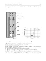
1 shows a typical pressure sensing (pulse) line inside a nuclear reactor containment (Lin K.
& Holbert K., 2010).
Radiation-Hard and Intelligent Optical Fiber Sensors for Nuclear Power Plants
121
Fig. 1. Typical pressure sensing (instrument) line inside a nuclear reactor containment.
Instrument lines can encounter a number of problems that can influence the accuracy,
response time of a pressure sensing system and decrease safety of NPP in consequence of
mechanical resonances which appear on frequencies up 200 Hz , for example, fig. 2 shows
transfer functions of a pressure sensing system (Lin K. & Holbert K., 2010).
Fig. 2. Transfer functions of a pressure sensing system with resonance frequencies
Exception pulse lines from join of pressure sensors to technological equipment and
pipelines in NPP is provided by Technical Regulations of the Russia (TR, 2000).
Performance of this requirement became real possible only at use of fiber optic
technologies. Advanced concept of construction of water-water nuclear reactors from
Russian nuclear research center "Kurchatov Institute" provides use of welded joints of gages
with equipment NPP instead of less reliable fitting connections that is possible with
Nuclear Power – Control, Reliability and Human Factors
122
application OFS with the big life time (up to 60 years) and with function of metrological self-
calibration (Buymistriuc & Rogov, 2009).
It is important to notice that begun using fiber-optical technologies of communication and
measurements in NPPs considerably improves their equipment. Really, typical NPPs used
hard wired point-to-point connections from field instrumentation to control systems and
panels in the control room. Essentially there is one wire per function or about 30 – 50
thousands wires coming from the field to the cable spreading room and then control room.
The use of optical fiber networks, which carry substantially more information and decrease
in 9 once weight of connections, instead of copper cabling, can eliminate 400 kilometers of
cabling and 12500 cubic meters of cable trays (GE, 2006).
Contemporary optical fiber sensors give a unique possibility to realize the principle of
remote measurement (fig. 1) .
Fig. 3. Concept of remote pressure measurements
1 – OFS; 2 – optoelectronic transceiver
When sensitive element 1 of an OFS placed in harsh environment can be moved away from
optoelectronic transceiver 2, which is under comfortable conditions of an equipment room,
at the distance up to 3000 meters by means of an optical cable option which replaces
undesirable pulse tubes very effectively.
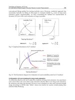
The design of the sensitive element of pressure OFS working with the measured
environment of a nuclear reactor without application of pulse tubes is such that its resonant
frequency lies in the range of frequencies above 80 kHz, i.e. inadmissible resonances in
nuclear reactors at frequencies below 200 Hz are structurally excluded. In fact, the resonant
frequency of longitudinal vibration of optical fiber Fabry-Perot interferometer (FFPI) in the
form of a quartz glass core is defined as
1
4.91 E
f
L
(1)
where Е - Young’ modulus of elasticity of a glass core, Pa
ρ – glass core density, kg/m
3
E/ρ - own rigidity, in particular for silica glass, 45х10
5
m.
Thus the sensor mechanical resonant frequency is defined by its length L = 0.001 … 0.1 m
and lies in the range f
1
= 10,4092 / L [kHz] = 104,092 … 10409,2 kHz.
Frequency resonant characteristic of a typical pressure OFS based on FFPI indicates Fig. 4.
Radiation-Hard and Intelligent Optical Fiber Sensors for Nuclear Power Plants
123
Fig. 4. A resonance frequency response of FFPI-based pressure OFS
OFS of acoustic emission, humidity and others parameters on the basis of coils of a fiber or
nano-coatings of an tip of a fiber have resonant frequencies a few tens in MHz.
Use the optical fiber technologies allowing to realize a principle remote measurements
changes a principle of construction of measuring systems of NPP and completely to solve a
problem of resonances of pulse lines.
Fig. 5. New advanced structure of the pressure sensing line inside a nuclear reactor
containment
Nuclear Power – Control, Reliability and Human Factors
124
Fig. 6. Transfer gain-frequency function of a pressure optical fiber sensing system
On fig. 5 the new structure of system of measurement of the pressure is shown, one of which
results of realization is full elimination resonances of the measuring channel as is shown in
fig. 6.
For maintenance of working reliability of offered measuring system, especially in zones
NPP with radiation presence, application radiation-hard optical fiber and cables is
necessary (TR, 2003).
3. Ionizing radiation hardness of OFS
Use of silica as a material for fiber optic sensors and measuring communication lines is an
effective solution both in terms of mechanical properties and radiation hardness of silica
fibers which are reached by modern manufacturers, for example, a method of entering and
retention of hydrogen in an optical fiber.
Another important factor of applying silica optical fibers under radiation conditions, in
particular for OFS based on silica optical fibers, is their low radiation induced losses in the
range of wavelengths between1150 nm and 1350 nm as is shown in fig. 7 (Fiedler et. al.,
2005).
Radiation hardness of OFS equaled earlier to a general dose of irradiation of about 1.2 MGy
with γ-radiation and 2.6•10
16
neutrons/cm
2
with a neutron fluence (Berghmans F. &
Decréton M., Ed.,1994) but now reaches doses of gamma radiation up to 23 MGy and
neutron flux 52 •10
16
neutrons/cm
2
(Fiedler et. al., 2005).
Photonic crystal fibers (PCFs) were also recently submitted to a number of nuclear
environments applications. In hollow core PCFs the light is essentially guided in air, which
may significantly decrease the radiation response of such waveguides compared to
conventional optical fibers. The structure used by us hole core PCF at 1000X and 10000X
imagnifying in a microscope is shown on fig. 8.
The permanent radiation induced attenuation (RIA) levels after radiation of PCF were found
to be very low. This was confirmed with hollow core PCF showing at least about 30 to 100
times lower RIA than the best present conventional optical fibers at 1550 nm with theoretical
Radiation-Hard and Intelligent Optical Fiber Sensors for Nuclear Power Plants
125
limit of total dose of gamma radiation over 1 GGy (Henschel H. et al. ,2005). Post-
fabrication treatment of the photonic band gap fiber with hydrogen gas has been reported to
improve the fiber’s resistance to radiation (Tomashuk A.; Kosolapov A. & Semjonov S.
(2006).
Fig. 7. Spectral transmission for 20% Ge doped silica optical fiber
Fig. 8. Structure of the hollow core PCF at 1000
X
and 10000
X
magnifying in a microscope.
For extreme dose situations, the light must initially be guided from the measurement
location using a hollow-core light guide. All known materials darken unacceptably in the
intense radiation field of a nuclear reactor core. However, reflective technologies are
available that have been shown to withstand comparable environments.
Conceptually, a hollow-core light guide is simply a mirror that has been formed into a
polished titanium tube as shown on fig. 9. This approach was used for measurements
temperature and the neutron flux in near-reactor environments (Holcomb D.; Miller D. &
Talnagi J. (2005).
Nuclear Power – Control, Reliability and Human Factors
126
The principal innovation of this approach is to combine optical and fiber optical
measurement components in a form suitable for deployment in a nuclear reactor core.
The main needs for in-pile concern the assessment of creep and growth of cladding
materials, or nuclear fuel rod behaviour, which require elongation measurements or
diameter measurements of cylindrical samples. Among others adaptations to the nuclear
environment, these OFS will need a radiation resistant fixing.
Fig. 9. Hollow-Core Light Guide Concept.
As the light reaches lower radiation environments, several different optical transmission
technologies become possible:
hollow core PCF or conventional radiation-hard optical fibers.
For total doses up to about 10
4
Gy, pure silica core, fluorosilica clad, multimode optical
fibers are suitable light guides.
4. Enhanced reliability of OFS in harsh environments
А standard version of FFPI has no face reflecting coverings and works based on natural
Fresnel reflections in the amount about 4%. For changing the sensitivity and dynamic range
of the pressure OFS , we used TiO
2
reflecting coverings.
The fibers are placed in magnetron sputtering (MS) machine and coated with TiO
2
by
vacuum deposition. The reason for using TiO
2
is that it has high refractive index (~2.4, vs.
1.4 for the silica fiber) over visible and infrared spectral ranges and strong bonding on glass
based materials. The MS machine is filled with a mixture of 70% argon and 30% oxygen so
that the titanium and oxygen atoms ejected toward cleaved fiber end and stick to the fiber
until the desired film thickness is reached. However, experiments have shown that adhesion
to glass and roughness of the TiO
2
coatings made by this method are not satisfactory.
Apparently on fig. 10, mean-quadratic deviation of the surface profile equal about 37.8
nanometers.
A coating with enhanced adhesion and long-term durability was obtained by a enhanced
method af atomic leyer deposition - method molecular layering (ML) (Buymistriuc & Rogov,
2009).
Synthesis was carried out by repeated and alternate processing of the surface of the fiber
end face by H
2
O and TiCl
4
steams removing the surplus of not reacted and formed by-
products after each stage of processing. Thus, not more than one monomolecular layer with
Radiation-Hard and Intelligent Optical Fiber Sensors for Nuclear Power Plants
127
the thickness of new structural units about 0.3 nanometers are added to the surface in each
cycle of ML reactions.
Fig. 10. Microscopic view of optical fiber tip with TiO
2
magnetron sputtering
With processing by TiCl
4
steams the reaction on the surface proceeds as follows:
(≡Si-OH) + TiCl
4
→ (≡Si-O-)
2
TiCl
2
+ HCl (2)
With processing by water steams the reaction on the surface proceeds as follows:
(≡Si-O-)
2
TiCl
2
+ 2H
2
O → (≡Si-O-)
2
Ti(OH)
2
+ 2HCl (3)
At this stage of the ML process we obtain a hydroxylated surface again but now OH-
groups are linked not with the atoms of silicon of the initial matrix but with the atoms
which are part of the imparted functional groups. The hydroxylated surface is processed
Nuclear Power – Control, Reliability and Human Factors
128
by TiCl
4
steams again. At this stage the second titanoxidechloride monolayer is formed as
follows:
2(≡Si-O-)
2
Ti(OH)
2
+TiCl
4
→[(≡Si-O-)
2
Ti(O-)]
2
TiCl
2
+2HCl (4)
Then a reaction product is again subject to processing by water steams. The process was
finished when obtaining coatings with thickness from 10 to 180 nanometers with a mean-
quadratic deviation of the surface profile about 1.4 nanometers, as shown in fig. 9 which
gives the view of the end faces of the optical fiber obtained by means of an atomic-power
microscope.
Fig. 11. Microscopic view of fiber tip with TiO
2
molecular layered nano-coating
An important advantage of such pressure OFS is its enhanced reliability determined by a
unitary structure of the sensor and extremely high adhesion of molecular coatings to silica
optical fibers. OFS fabricated with new ML technology possess the greatest reliability (on
distribution of Weibull) than usual MS method as shown on fig. 12.
Radiation-Hard and Intelligent Optical Fiber Sensors for Nuclear Power Plants
129
Fig. 12. Weibull distribution plots for basic fiber and fibers coated by using ML and MS
technologies
5. Principles and constructions of intelligent OFS
Information redundancy of optical fiber sensors, as well as possibility to their
programmable tuning in combination with a minimum structural redundancy allow to
develop the so-called intelligent sensors with a function of metrological self-checking. The
function of metrological self-checking of optical fiber sensors is provided with their
multimodality, i.e. with their similar dependence of an output signal on several variable
parameters, f.e., with their dependence on a variable pressure at a constant optical spectrum
of an input signal and, accordingly, on a readjusted optical spectrum of the signal at a
constant pressure. Construction of intelligent sensors of new generation assumes presence at
such sensors of structural (internal) and/or information (external) redundancy
(
Taymanov
R. & Sapozhnikova K., 2008).
Microelectronic sensors of physical quantities generate the unimodal output signal Y
depending on change only of one parameter of sensor R:
0
(;)YY kRxt
(5)
where Y – an output time signal, Y
0
– initial value of an output signal;
ΔR – change of parameter of a sensor, caused in the measured physical quantity x in time t;
k – proportionality factor.
That is, microelectronic sensors do not possess necessary information redundancy. To
provide self-checking of such sensors by creation of information redundancy, for example
giving on them influences of physical quantity of known value – it is almost impossible
while in process controllable equipment in real time. Therefore intelligent microelectronic
Nuclear Power – Control, Reliability and Human Factors
130
sensors are under construction by creation of structural redundancy (embedding of the
reference sensor, the additional sensor with parameters close to the basic sensor, etc.) that
not always is the optimum decision.
5.1 Self-checking OFS
Application of a fiber optic Fabry-Perot interferometer for measurements of pressure and
speed of pressure variation in water reactors of NPPs contributes to improving their safety
and long-term metrological stability, which demands for intelligent sensors.
5.1.1 Basic principles
By means of fast tuning of the spectrum of an optical source it is possible to make self-
calibration in the course of continuous work of the pressure gauge. Optical cables including
connectors, splices, and other components are tested by evaluating the optical losses
relationship along the cable.
OFS of physical quantity creates the multimodal output signal depending at least from two
parameters of the sensor, for example for OFS based on FFPI output signal I
s
depends on
change of length of optical resonator G and change of a wavelength of light λ:
0
0
4
1(;)
()
s
II Cos Gxt
t
(6)
where I
0
– initial intensity of light coupled into FFPI.
The output signal such OFS according to the equation (2) changes depending on change of
length of a cavity of the resonator ΔG, caused by pressure, and depending on change of the
central optical wavelength of the coherent sensing channel Δλ
0
, provided, for example, by
the tuneable spectral optical filter (TSOF) as is shown in fig. 13.
Fig. 13. Response of FFPI output from resonator cavity length and optical source peak
wavelength changes
Radiation-Hard and Intelligent Optical Fiber Sensors for Nuclear Power Plants
131
Additional possibility at such intelligent OFS is possibility of stabilization of a quiescent
point (Q-point) on its linear site calibration characteristics by fine tuning of a wavelength of
light on value δλ
0
sensing channel, compensating a deviation of initial length of a cavity of
the optical resonator δG, caused by destabilizing factors during long operation of the sensor.
Thus, it is obvious that for realization FMSC interferometric OFS possess necessary
information redundancy.Structural redundancy of OFS at realization FMSC is minimal and
is reduced to application of the TSOF, as shown on the scheme fig. 14.
On such principle has been realised the intelligent pressure OFS with function metrological
self-checking (FMSC) at long operation in extreme conditions
(Buymistriuc G. & Rogov
A.,2009).
Speed of tuning of a modern TSOF, for example the models “FFP-TF” from “Micron Optics,
Inc” or the acousto-optical tuneable filter models “AOTF” from “Fianium, Inc” is rather high
also the period of tuning time T on all set spectrum. For example in sequence T = t
3
- t
1
on
fig. 15, makes value of an order 0,1 … 0,4 microsecond that it is enough for the majority of
modes of measurement of pressure, deformation, vibration, temperature, level of etc.
controllable industrial equipment.
Fig. 14. Intelligent pressure OFS
1 – FFPI; 2 – optical cable; 3 – optical coupler; 4 –light emitting diode; 5 –TSOF;
6 –photodiode; 7 – microcontroller
5.2 Algorithm
Procedure of self-checking of pressure OFS on the basis of FFPI consists of the following
consecutive steps.
Step 1. When OFS is manufactured, its calibration characteristic is measured:
I
с
= f(ΔG{P}) at λ
0
= const
by means of a precision pressure calibrator (for example from DPI-610 from “Druck, Ltd”)
and stored as initial data in the energy-independent memory of the device.
Nuclear Power – Control, Reliability and Human Factors
132
Fig. 15. A spectral peak in time change of tunable optical filter of the OFS
Step 2. While OFS is in service after a certain period of time, which may be equal to an
periodic testing interval of the device, the current calibration characteristic of the
gauge is measured without stopping the process of pressure measurement :
I
’
с
= f(λ) at ΔG{P} = const
by fast tuning of the central wavelength of the spectral optical filter transmission [λ
0
→ λ
2
] –
forward scan, and [λ
2
→ λ
0
] – reverse scan, as shown in fig. 15. The speed of the filter tuning
should exceed the rate of the measured pressure change.
Step 3. The graduation characteristic of the pressure OFS is compared with the initial data
of calibration and corresponding correction factors are calculated.
Step 4. The measurement of pressure by means of OFS with using correction factors
obtained at step 3 is continued.
Thus, interference OFS is internally inherent necessary information and structural in
redundancy effectively to carry out FMSC.
5.3 Estimation of error
Error of measurement of the intelligent OFS, caused by instability of the central wavelength
of TSOF, i.e. shifted spectra TSOF and light emitting diode and casual displacement of
spectral characteristics of the filter us has been investigated by modeling and experimental
check.
Distortion
s’ of an output signal s, is described by following expression:
4
'1 1
2
c
o
I
ss Cos G
I
(7)
where γ
c
– contrast (“fringe visibility”) of interference.
The normalised error of measurement of pressure δs/s, caused by shift Δλ the central
wavelength of the filter, is described by expression:
2
0
max
14
()
2
r
sdIG
abs
sId
(8)
Radiation-Hard and Intelligent Optical Fiber Sensors for Nuclear Power Plants
133
A case non-centering (casual displacement) of a wavelengths of the optical filter and a
source of optical radiation in the course of long operation.
By means modeling and experiences is established that spectrum mismatching of the TSOF
with a light source poorly influences an error of measurements of OFS. Big shifted spectral
mismatch, above 3 nm, gives metrological error less then 0.02%.
Besides by tuning TSOF with feedback included on an output signal it is possible to provide
stability of a quiescent point (Q-point) interferometric OFS that is to realise the intelligent
gauge with self-correction.
Possible application of adaptive OFS is their use as additional measuring transducers of the
self-checking channel at construction of intelligent gauges of pressure with elastic elements
and gauges of level and other physical quantities for the purpose of substantial growth of
their actual interval between testing.
5.4 Intelligent acoustic emission OFS
Was investigated also methods of realization of intelligent OFS on other principles of
operation, in particular possibilities of intellectualizing of the acoustic emission OFS based
on intrinsic optical fiber effect of Doppler (Li F. et al., 2009).
A Doppler shift of frequency f
D
under influence of a sound wave a is defined as
0
(;)
()
D
ndLat
f
tdt
(9)
where n –index of refraction of a fiber; λ
0
– wavelength of laser radiation; L – length of
fiber sensing element; a – acoustic signal; t – time.
Apparently from a equation (9) and fig. 4 that frequency OFS has information redundancy –
dependence Doppler shift of frequency both from change of length of fiber L, and from
change of frequency of laser radiation f
0
, and structural redundancy – the tunable laser
diode.
Fig. 16. Intelligent acoustic emission OFS
1-fiber coil sensing element; 2, 6 – fiber optic couplers; 3 – tuneable laser diode;
4 – acousto-optical frequency shifter; 5 – RF generator; 7 – frequency detector;
8- microcontroller