Access for Dialysis: Surgical and Radiologic Procedures - part 4 pot
Bạn đang xem bản rút gọn của tài liệu. Xem và tải ngay bản đầy đủ của tài liệu tại đây (8.18 MB, 44 trang )
117
Dual Lumen Catheters for Dialysis
5
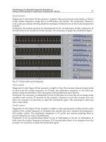
Fig. 5.21. This adhesive device supplied in the Tesio kit is taped to the patient’s chest to
prevent catheters from being pulled and only lasts a few days. Patients must be taught to
care for their catheters to minimize complications. Catheters should not hang down
freely, which causes slow migration and eventually dacron cuff migration/exposure/in-
fection. Catheters can be taped in a loose curvilinear fashion or secured in the bra
(females) to allow free movements at the exit site, avoiding pulling.
Removal of Cuffed Catheters
Removal of cuffed catheters is indicated for tract infection, sepsis, positive blood
cultures and is the catheter is no longer needed.
Depending on where the cuff is located, two techniques are used.
1. The cuff is located immediately adjacent to the exit site. In this case, the exit
site is anesthetized with 1% lidocaine (Fig. 5.22A). The exit site is dilated
slightly with a mosquito hemostat or incised with a knife, and the catheter
may be lodged out with this simple procedure (Fig. 5.22B). In some cases
where the cuff is more incorporated, a small skin incision longitudinal to the
catheter is used with sharp and blunt dissection around the cuff, which will
release the catheter. Usually there is back bleeding which is temporarily stopped
by finger pressure (Fig. 5.22C). Compression of the exit site for about 30
minutes with the patient sitting up will usually prevent further bleeding.
However, the author recommends a Figure-of-eight suture with nylon or
PDS to prevent backbleeding (Fig. 5.22D). The patient is asked to keep
pressure on the site for the next 1-2 hours, and avoid strenuous physical
activity for the next 24-48 hours (Appendix IV).
2. In cases where the cuff is located further up the subcutaneous tract, the area
on top of the dacron cuff is infiltrated with 1% Lidocaine. A transverse inci-
sion is made (Fig. 5.23A). The catheter is isolated distal to the cuff, clamped
with a hemostat (Fig. 5.23B) and divided distal to the hemostat (Fig. 5.23C).
The catheter may now fall out from the exit site. The cuff is dissected free,
exposing the catheter proximal to the cuff. Often there is a sheath of tissue
surrounding the catheter at this point. A pursestring suture is placed around
the catheter, grabbing the tissue around the tract (Fig. 5.23D). This pursestring
suture of PDS is tied as the catheter is pulled out to prevent backbleeding.
118
Access for Dialysis: Surgical and Radiologic Procedures
5
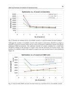
Fig. 5.22A. Removal/exchange of cuffed dual lumen catheters; in this case, the cuff is
immediately adjacent to the outside. After infiltration of lidocaine 1% and removal of
concentrated heparin in the ports, the cuff is dissected free with a knife, hemostat or
sharp scissors.
Fig. 5.22B. When the cuff is free, the catheter is pulled out in its entirety (Appendix IV).
119
Dual Lumen Catheters for Dialysis
5
Fig. 5.22C. Usually there is back bleeding, which is temporarily stopped by finger pres-
sure. Compression by the patient of the exit site for 30 minutes usually prevents further
back bleeding.
Fig. 5.22D. The author recommends a figure-of-eight suture to prevent any future back
bleeding. In addition, the patient is asked to keep pressure on the site for the next 1-2 hrs
and avoid strenuous physical activity for 24-48 hours.
120
Access for Dialysis: Surgical and Radiologic Procedures
5
Fig. 5.23A. When the cuff is at a distance from the exit site, a cut down over the cuff is
necessary. (When the cuff is at skin level blunt dissection is all that is needed around the
cuff).
Fig. 5.23B. The catheter is clamped distal to the cuff and cut/divided.
121
Dual Lumen Catheters for Dialysis
5
Fig. 5.23C. The cuff is dissected free to expose the catheter proximal to the cuff.
Fig. 5.23D. A pursestring suture, i.e., 4-0 PDS’ is placed around the catheter and tied as
the catheter is pulled to prevent back bleeding. Lastly, the suture (if present) at exit site is
cut and the catheter pulled out of the exit site.
122
Access for Dialysis: Surgical and Radiologic Procedures
5
Fig. 5.24. Correctly placed, the catheter will make a smooth, lateral curve at the neck
level, avoiding kinking.
The skin incision is closed with one or two subcuticular PDS sutures and
covered with a 4x4 dressing and bio-occlusive dressing (Tegaderm
®
). The
patient is asked to keep pressure for the next 1-2 hours and avoid strenuous
exercise for 24-48 hours (Appendix IV).
The Ideal vs Kinked Catheter
The ideal catheter on chest X ray describes a smooth right-side, lateral curve
without kinking (Fig. 5.24). The catheter lines end at the right atrium/SVC level.
Kinking usually occurs at the internal jugular vein insertion site (Fig. 5.25A-F).
When removed, this stiffer catheter also describes the central vein anatomy (Fig.
5.25C). Kinking may involve both ports, or as in this case only the arterial (red)
port (Fig. 5.25C-D). Ways to avoid a kinked catheter include wide smooth subcuta-
neous tunnel achieved by bending the tunneler. Also a lower jugular approach less-
ens the likelihood of kinking at the vein entrance level. Rarely, despite optimal
placement, kinks may occur (Fig. 5.25E-F).
Exchanging Cuffed, Tunneled Catheters
The indications for changing catheters are outlined in Table 5.2 and vary with
the type of catheter. Generally, changing cuffed catheters over a guidewire using the
same exit site is not recommended. The authors prefer the following technique, if
technically feasible.
A skin incision is made at the neck level, close to or at the previous neck inser-
tion site (Fig. 5.26A). The catheter is dissected free and surrounded with a vessel
loop (Fig. 5.26F). The new catheter is inserted from the upper chest using a new exit
123
Dual Lumen Catheters for Dialysis
5
Fig. 5.25A. Classic kink of catheter with a sharp angle at the IJ exit. This is caused by too
sharp a “turn” of catheter at the IJ vein.
Fig. 5.25B. Close up view of same catheter.
124
Access for Dialysis: Surgical and Radiologic Procedures
5
Fig. 5.25D. Close up view of the kink at the neck IJ level.
Fig. 5.25C. The removed catheter outlines the central vein anatomy.
site, usually lateral to the previous one. The new catheter is tunneled and brought
into the neck wound. The catheter to be removed is guidewired, either from the end
by making a small incision in one of the catheter lines at the neck wound. It is not
recommended to completely divide the catheter at this level since it may be lost,
causing foreign body embolization (Fig. 5.26C). A guidewire is inserted, and the
catheter can now be removed. Back bleeding is prevented by finger pressure. The
guidewire is pulled out of the old catheter. The tract may be dilated over the guidewire,
125
Dual Lumen Catheters for Dialysis
5
Fig. 5.25E. Despite a smooth curve of this catheter, an undulation involving one lumen
was seen immediately after placement. The kink is magnified in image F. Patient under-
went uneventful dialysis with >300 ml/min flow the following day. (No follow-up x-rays
of this catheter available!)
Fig. 5.25F. Close up view of kinked catheter.
126
Access for Dialysis: Surgical and Radiologic Procedures
5
Fig. 5.26A. Make an incision at the previous neck insertion site; the catheter is mobilized.
Fig. 5.26B. The catheter is pulled up. Catch the catheter with a vessel loop. At this point
the catheter may be partially divided to allow guidewire insertion. This will also prevent
losing the catheter into the blood stream.
127
Dual Lumen Catheters for Dialysis
5
but may not be needed. The new catheter is inserted as described above, using the
introducer sheath. Since the tract is already present, the introducer sheath may not
be necessary. In cases of split ash, a special technique can be used where the guidewire
is inserted into the distal venous port and using the side holes, the guidewire can
come out of this venous port and now go into the end of the arterial port, and the
catheter can be inserted over one guidewire without using the introducer sheath.
Sometimes using a stiff shaft hydrophilic wire ( “glidewire”) facilitates these steps,
since the regular stiff guidewire produces too much friction while in the catheters.
Also, as an alternative method, a rapid exchange can be achieved with dual guidewires,
one in each port avoiding “hang ups” at the venous site. The old catheter is now
removed, using cut downs over the dacron cuff, as described above. The neck wound
is closed with subcuticular PDS, and the catheter is again sutured to the exit site as
described above after having been adjusted based on fluoroscopy.
Split Ash Single Guidewire Insertion
Figure 5.27 illustrates a useful technique of insertion of a split ash catheter. The
old catheter is removed over a guidewire inserted from the outside (blue) port or
from the neck incision (Fig. 5.26A-B), where a small cut is made into the catheter.
The author advises against completely dividing the catheter at this site (Fig. 5.26C)
for risk of losing it. A wet stiff hydrophilic 0.035” (0.89 mm) glidewire is
Fig. 5.26C. The old catheter with cuff is removed. No back bleeding should occur. Do
not completely divide the catheter at the neck incision level as shown in this image,
since the operator can lose stability and lose the catheter into the bloodstream, causing
foreign body embolization.
128
Access for Dialysis: Surgical and Radiologic Procedures
5
Fig. 5.27A. As the old catheter comes out, finger pressure is applied to prevent back bleed-
ing. The guidewire remains in the IJ and preferably down in the IVC (confirmed by fluoros-
copy). The end of the wire is now inserted into the blue port of the split ash.
recommended to avoid getting stuck, especially when the catheter is sharply curved
from the left side insertion.
As the old catheter comes out, finger pressure is applied to prevent back bleed-
ing. The glidewire remains in the IJ and preferably down in the IVC (confirmed by
fluoroscopy).
The end of the wire is now inserted into the blue port of the split ash (Fig.
5.27A), brought out through the second side hole of this port (Fig. 5.27B), inserted
into the end of the red port (Fig. 5.27C), and fed back to the external red port and
secured (Fig. 5.27D). The split ash catheter is now inserted into the IJ and posi-
tioned under fluoroscopy (Fig. 5.27E). The glidewire is now removed. Both ports
checked for patency and primed.
This technique allows a water tight seal and prevents air embolism, even when
the patient is not in the Trendelenburg (head down) position. This one guidewire
insertion could also be used in first time catheter placement after dilating the tract
over the guidewire, but replacing the last step, i.e., not using the sheath (Fig.
5.14-5.15), with the single wire steps.
A two guidewire insertion technique for other catheters can be used, in which
both ports will have one glidewire as the catheter is inserted.
129
Dual Lumen Catheters for Dialysis
5
The Infected Catheter
There are different degrees and severity of catheter infections based on clinical
findings.
Patients may have a perfect looking catheter, dialyze well but experience low
grade fever, occasional chill, especially during dialysis. This is likely to represent an
intraluminal infection that is treated with antibiotics and catheter exchange using a
new exit site. Others may have the same symptoms and in addition a red, inflamed
exit site or tender catheter tract. Most surgeons would permanently remove such
catheters. The authors take a slightly different approach. After 24-48 hours of IV
antibiotics (i.e., vancomycin and gentamicin), symptoms improve or disappear. At
that point the catheter is replaced through a new exit site. Antibiotics are continued
for 10-14 days. In patients with purulent drainage around catheter and clinical signs
of sepsis, the catheter must urgently be removed. New access can be placed when the
patient has been afebrile for >48 hours or blood cultures are negative. Dialysis is
delivered through temporary femoral percutaneous catheters.
Fig. 5.27B. The end of the wire is now brought out through the second side hole of this
port.
130
Access for Dialysis: Surgical and Radiologic Procedures
5
Fig. 5.27C. And inserted into the end of the red port.
Fig. 5.27D. Then fed back to the external red port and secured.
131
Dual Lumen Catheters for Dialysis
5
Fig. 5.27E. The split ash catheter is now inserted into the IJ and positioned under fluoros-
copy.
Fig. 5.28A. The skin is marked for (in this case) split ash subcutaneous tract and exit site.
Skin incision is marked for catheter exposure.
132
Access for Dialysis: Surgical and Radiologic Procedures
5
Percutaneous Catheter Conversion to Cuffed
The technique described here (Fig. 5.28) applies to the right internal jugular
vein site. However, the principles apply to any site. The right neck and the entire
percutaneously placed catheter are thoroughly prepared with Betadine solution. The
“wing” often sutured to the skin is removed. The skin is marked for (in this case) the
split ash subcutaneous tract and exit site (Fig. 5.28A). Skin incision is made and the
catheter is exposed (Fig. 5.28A), the catheter is mobilized and surrounded with a
vessel loop (Fig. 5.28B). The split ash is now pulled into the neck wound from its
Fig. 5.28B. The catheter is mobilized and surrounded with a vessel loop.
Fig. 5.28C. The split ash is now pulled into the neck wound from its exit site.
133
Dual Lumen Catheters for Dialysis
5
Fig. 5.28D. The blue port is used for a stiff guidewire (0.035” or 0.89 mm, straight or
angled) insertion into the percutaneous catheter that is then removed leaving the guidewire
in place, confirmed by fluoroscopy. Ideally, the guidewire goes down into the inferior
vena cava.
exit site (Fig. 5.28C). The blue port is used for a stiff guidewire (0.035” or 0.89 mm,
straight or angled) insertion into the percutaneous catheter (Fig. 5.28D) that is then
removed leaving the guidewire in place, the position confirmed with fluoroscopy.
Ideally, the guidewire goes down into the inferior vena cava. The guidewire is now
retrieved into the neck incision wound using the vessel loop (Fig. 5.28E). The
guidewire is now used to insert the split ash using the single wire technique (Fig.
5.27) or the sheath technique as described in Fig. 5.14D.
The Thrombosed Catheter
Several options, generally in a stepwise, progressive fashion are available for deal-
ing with a nonfunctioning catheter. One or both ports may be partially or com-
pletely occluded for either pull, return flow or both.
1. First the operator should attempt vigorous flushing with a 10 or 20 cc sy-
ringe to aspirate the clot.
2. Second step includes using brushes that rotate inside the lumen breaking
loose clots. The authors have used the ureteral cytology brushes for this pur-
pose, with questionable results.
3. Thrombolytic agents may be used, such as t-PA (tissue plasminogen activator),
using indwelling or 2-4 hour infusion of 1 mg per port per hour (Table 5.6)
4. Often there is a fibrous sheath surrounding the catheter. This will require
interventionalradiology to strip (snare) from a femoral vein approach. Re-
cent studies suggest catheter exchange is superior to stripping (Table 5.6).
134
Access for Dialysis: Surgical and Radiologic Procedures
5
Fig. 5.28E. The guidewire is now retrieved into the neck incision wound using the vessel
loop.
5. These procedures may be combined with thrombolytic treatment, i.e., t-PA
injected as a bolus or infusion over 2-4 hours.
6. Balloon dilatation to 12-14 mm of the innominate vein, SVC and the
rightatrium in order to disrupt the fibrin sheath is carried out.
7. Finally, the catheter can be exchanged over guidewire to a new exit site or
inserted on a new side. In either case the catheter should be inserted slightly
further beyond the fibrous sheath to ensure catheter longevity. The sheath
can be visualized through an SVC/venogram as the catheter is removed. If
present, the sheath is subjected to 8-10 mm balloon angioplasty.
Selected References
1. Merport M, Murphy T, Egglin T et al. Fibrin sheath stripping versus catheter
exchange for the treatment of failed tunneled hemodialysis catheters: randomized
clinical trial. JVIR 2000; 11:1115-1120.
2. NKF-DOQI Clinical Practice Guidelines for Vascular Access. New York: National
Kidney Foundation, 1999.
135
Dual Lumen Catheters for Dialysis
5
Table 5.6. Protocol for clearance of thrombosed catheters
Clotted/Thrombosed Catheters
1. Attempt vigorous saline flush/aspiration.
2. If unsuccessful, try repeated, small, frequent t-PA catheter injections (both ports) or
infusions depending on local protocols.
3. Radiologic stripping of catheter (femoral vein access).
4. Exchange catheter over guidewire, using an incision at neck site exploring the
catheter; always use a new tract and exit site. Inside tract may require balloon
angioplasty. Insert an introducer sheath if the IJ or IJ/SVC junction is stenotic.
5. Techniques used require sound judgment and should vary depending on local
availability of equipment, technical expertise and patient condition.
6. Patients with a history of fever need preop antibiotics (i.e., vancomycin and
gentamicin). If no evidence of tract infection, i.e., tenderness or drainage, it is
assumed to be intraluminal catheter infection, and new catheter is placed. Using
the same cutaneous tract or exit site is strongly discouraged.
CHAPTER 6
Access for Dialysis: Surgical and Radiologic Procedures, 2nd ed.,
edited by Ingemar J.A. Davidson. ©2002 Landes Bioscience.
Abdominal Catheters for Peritoneal
Dialysis: A Detailed Surgical Procedure
Ingemar J.A. Davidson; Illustrations: Stephen T. Brown
Background
The percentage of end stage renal disease (ESRD) patients using peritoneal di-
alysis (PD) varies markedly between different countries and societies. In the US, PD
patients constitute 16% while in some European countries this number is between
40-50%. Patients typically suited for PD are young professionals who have regular
working hours, travel needs and require a high degree of freedom. PD can be done
intermittently (IPD), continuously with several exchanges throughout the day
(CAPD), or continuously during the night with a cycling machine while the patient
is asleep (CCPD). The dialysis hypertonic (dextrose) solution prescribed may vary
from 1.5%-4.25% to regulate body water content.
Preoperative Considerations
A number of factors are associated with the likelihood of success with peritoneal
dialysis (Table 1). Patients with diabetes, impaired vision, obesity, poor compliance
or understanding of technical details and lack of dexterity are less likely to benefit or
do well.
The decision as to what access to place in a specific patient requires a well-in-
formed patient and effective communications between treating team members, that
is nephrology, surgery and dialysis personnel.
Detailed Operative Procedure
Marking of The Skin
With the patient standing prior to surgery, the incision, as well as the intended
subcutaneous tract and exit site of the catheter are marked with an indelible pen
(Fig. 6.1). This is especially important in case of abundant abdominal fat that changes
position at standing (60% of the US population is overweight). An exit site away
from the beltline is preferred. Possible future transplant incision sites may be taken
into consideration. Therefore, in a virgin abdomen, the left side is chosen because
the right iliac fossa is the preferred site for a first kidney transplant.
Choosing the Catheter
The different catheters, type, lengths, number of cuffs and manufacturers are
detailed in Table 6.2. It is the author’s strong opinion that only curled (pigtail) type
catheters should be used. Therefore, the straight catheters have been excluded from
the table. The curled catheter comes in left- and right-sided configurations. The
only difference between the two is the orientation of the radiopaque line on the
137Abdominal Catheters for Peritoneal dialysis
6
Fig. 6.1. The author prefers the paraumbilical transrectus muscle approach (level guided
by patient size and catheter length). The catheter my be exteriorized at the time of
placement (A) or buried subcutaneously (Moncrief method), to be externalized 4-5 weeks
later (B).
Table 6.1. Factors influencing the dialysis modality decision
Patient desire, including lifestyle, profession, age, body habitus
Patient restriction to learn technique, i.e., impaired vision, advanced age, lack of
manual dexterity
Distance to hemodialysis unit
Socioeconomic factors
PD training facility availability
Previous abdominal surgery with adhesions
Recent or recurrent abdominal infections, i.e., diverticulitis
Overweight, hygiene issues
Heparin intolerance
Inability to establish vascular access
138 Access for Dialysis: Surgical and Radiologic Procedures
6
Table 6.2. Commercially available curled peritoneal dialysis catheters
Length Length
Company Product Model Cuffs Overall Internal Comment
Vas Cath Pigtail 2 56 30
Vas Cath Pigtail 2 60 34
Vas Cath Acute Pigtail 1 56 30
Vas Cath Acute Pigtail 1 60 34
HMP Neostar 1 39.25, 41, 56.5, 60
HMP Neostar 2 56.5, 52
Quinton Curl Cath 2 57, 62
Quinton Curl Cath 1 39, 57, 60
Quinton Curl Cath Loose 62 variable cuffs placed at time of implant
Quinton Curl Cath Swan Neck 2 62.5 41 L/R radiopaque strip
Quinton Curl Cath Missouri 2 62 42.3 Swan Neck, L/R radiopaque, lean-average
Quinton Curl Cath Pre-Peritoneal 2 112.8 Swan Neck, L/R radiopaque,
Moncrief-Popovich 2 62.5 42.5 Swan Neck, L/R radiopaque
It is the author’s opinion that only “pigtail” catheters should be used for patency reasons. The swan-neck catheters come in ri
ght and left
interchangeable configurations, referring to the side with the radiopaque strip.
139Abdominal Catheters for Peritoneal dialysis
6
catheter. This line provides easy x-ray visualization of the catheter course and may
be useful in identifying possible kinks in the catheter. The direction of the curl will
be left or right in the pelvis depending on which side the catheter is placed, a matter
of no consequence. The number of cuffs is a matter of surgeon’s choice. Properly
positioned, the second cuff is placed 1-2 cm away from the skin. The author recom-
mends the two cuff catheter. The sliding of the catheter at the exit site, as is the case
with only one cuff, is likely to induce catheter tract infection. The proper position of
the curled portion in the pelvic space is obtained by appropriately choosing catheter
length and the incision site (Fig. 6.1). Figure 6.2A shows two types of catheters
contrasting one versus two cuffs and swan neck preformed versus regular. The au-
thors prefer the two cuffed, swan neck type catheter (Fig. 6.2B).
Anesthesia
As in all cases of hemodialysis access, patients are uremic, often with significant
comorbidity, most commonly heart disease, hypertension, anemia and diabetes.
Dosing of anesthesia drugs must be decreased accordingly and given with great cau-
tion to avoid serious complications such as intraoperative circulatory arrest, hy-
potension, jeopardize the procedure itself or inducing other complications such as
strokes, cardiac events or requirements for intubation and prolonged postoperative
ventilator treatment. PD catheter placement is preferably placed under local anes-
thesia, i.e., epidural with careful sedation; young otherwise healthy individuals may
be safely given general anesthesia. HIV positive individuals, in the author’s view, are
candidates for epidurals or general anesthesia to protect the OR personnel.
Fig. 6.2A. There are several types of Tenckhoff’s catheters available, with one or two
dacron cuffs. The innermost cuff is placed between the peritoneum and the posterior
fascia; the outermost cuff is placed subcutaneously 1 cm from the sign. In cases of one
cuff, this goes at the peritoneum site. Using a swan neck type curved exit portion, the
Moncrief design calls for a 6 week period of curing the entire catheter and then external-
izing the part distal to the second outermost cuff. Since the introduction of the pigtail
catheter, intraabdominal obstruction by omentum has been largely eliminated. For com-
plete listing of catheters, see Table 6.2.
140 Access for Dialysis: Surgical and Radiologic Procedures
6
Antibiotics
Cefazolin (Ancef) 1 gram IVPB or vancomycin 1 gram IVPB is given or started
before skin incision. Both the skin incision and exit site have been marked with the
patient standing. The abdomen is shaved as needed and prepped and draped as per
routine. 1% lidocaine with sodium bicarbonate added is used (2 ml of 8.4%
NaHCO3 in 20 ml 1% lidocaine) will cause less burning during injection.
Paraumbilical Approach
This is the author’s preferred choice and therefore described in detail. In this
case, skin incision is placed approximately 2 cm on either side of the umbilicus (Fig.
6.1). The abdominal wall anatomy in relation to catheter placement is depicted in
Fig. 6.3A. Dissection is carried down sharply and/or with electrocautery, maintain-
ing exact hemostasis. The anterior rectus muscle fascia is divided longitudinally. The
rectus muscle layers are split bluntly. Intrarectus muscle vessels are electrocauterized
or clipped. The posterior fascia is exposed. Exposure is improved by using a Weitlander
retractor (Fig. 6.3A,B).
Using fine scissors, the peritoneum is opened for 3 mm (Fig. 6.3A-B). A 2-0
Prolene
®
purse string suture, including the posterior rectus fossa and the peritoneum,
is placed in a manner that the tie will be located behind and cephalad of the cuff.
Fig. 6.2B. The swan neck (proximal), pigtail (distal), 62.5 cm double cuffed Quinton
peritoneal dialysis catheter. The parts of the catheter are marked as follows: PT: Pigtail;
PPC: Preperitoneal Cuff; SN: Swan Neck; SQC: Subcutaneous Cuff; EP: Externalized
Portion. (Sherwood Davis & Geck, St Louis, MO 63103.(800) 962-9888).
141Abdominal Catheters for Peritoneal dialysis
6
The catheter is placed using the stiff guidewire (Fig. 6.4A) inserted into the catheter
to make the curled position straight (Fig. 6.4B-C) facilitating insertion through the
small peritoneal opening (Figs. 6.3 and 6.5). Also, the semi-sharp tip of the stiff
guidewire must not pass outside the straightened pigtail to avoid visceral injuries
when inserted (Fig. 6.4D). Once inside the abdomen, the catheter with the guide
slides down along the anterior abdominal wall. No force must be used. Should resis-
tance occur, redirection of the catheter is attempted until the pelvic area is reached.
At this point the stiff guidewire is slowly removed with one hand holding the PD
catheter in place at the exit site. Sliding of the guide is greatly facilitated by flushing
the PD catheter with saline prior to its insertion. Once fully inserted the pursestring
suture is tied snugly around the catheter (Fig. 6.5). The stitch is tied behind in the
cephalad direction and attached to the posterior aspect of the cuff. A second
pursestring suture is not needed. The catheter is held in the cephalad direction to
maintain the pelvic position of the curled portion. Next the catheter is pulled through
the anterior rectus fascia (Fig. 6.6), using a sharp stylet tunneling device (Fig. 6.7A-B).
A mosquito hemostat may be necessary to widen the anterior rectus fascia (Fig. 6.6)
to allow passage of the second dacron cuff to be placed at the skin exit site. This step
will definitely secure the vertical direction of the catheter making malposition of the
catheter unlikely.
Fig. 6.3A. Incision, dissection of abdominal wall anatomy with posterior rectus sheath
exposed and exposure of wound for PD catheter placement. The rectus muscle is split
bluntly. Hemostasis obtained with electrocautery. A 3 mm hole is made through the
posterior rectus fascia and the peritoneum. A pursestring suture (i.e., 2-0 Prolene
®
) is
placed. The catheter is ready for insertion.