Access for Dialysis: Surgical and Radiologic Procedures - part 5 pps
Bạn đang xem bản rút gọn của tài liệu. Xem và tải ngay bản đầy đủ của tài liệu tại đây (8.88 MB, 44 trang )
161
Evaluation and Intervention for Hemodialysis Vascular Access
7
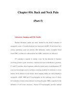
Fig. 7.2. Two types of tunneled dialysis catheters: A) Double tip or split catheter, as
typified by the Ash split catheter (polyurethane) and B) the single catheter double lumen
catheter shown here as a Hickman catheter (silicone rubber).
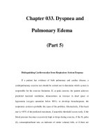
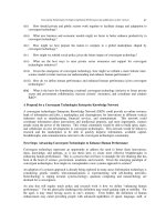
Fig. 7.3. Catheter size has a direct effect on flow. This explains the greater dialysis effi-
ciency with a cuffed catheter 14.5F, and a temporary catheter 12F.
162
Access for Dialysis: Surgical and Radiologic Procedures
7
and optimal catheter tip length and positioning. Knowledge of central venous
anatomy is imperative when placing central catheters (Fig. 7.4). I find the best func-
tion is achieved when (Fig. 7.5):
• the catheter is low in the neck in the internal or external jugular vein, with
the tips extending inferior to the cavo-atrial junction in the right atrium,
• the exit site is just lateral to the mid-clavicle, and
• the tissue in-growth cuff is 1-2 cm deep to the skin.
These criteria necessitate measurement of the distance to the right atrium to
correctly choose a catheter of appropriate length. Also breasts should be retracted
caudally when choosing the catheter exit site to prevent displacement of the catheter
by gravity. Split catheters are not position dependent, but single dual-lumen cath-
eters should have the arterial port facing centrally toward the major pool or right
atrial blood. Remember that the catheter is placed when the patient is recumbent
and will foreshorten when the patient sits or stands erect.
Catheter dysfunction is often related to the catheter tip design employing mul-
tiple side holes in the catheter tip to improve flow during dialysis, but allowing
thrombus to form between dialysis treatments because of hemostasis within the
catheter tip (Fig. 7.6). The routine practice of explosive catheter irrigation before
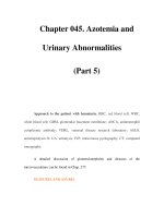
Fig. 7.4. Anatomy of the superior vena cava and right atrium and ventricle.
163
Evaluation and Intervention for Hemodialysis Vascular Access
7
connection to the dialysis machine will greatly improve long-term catheter func-
tion. Nursing manuals, however, prohibit most dialysis nurses from performing this
simple preventive maneuver. Access physicians should give specific orders to have
this maneuver performed. The other common cause of catheter dysfunction is the
development of a fibrin “biofilm” sheath that often acts as a valve to prevent aspira-
tion through the arterial port (Fig. 7.7). In 100 consecutive catheter exchanges with
angiography to evaluate for the presence of a sheath, we found a significant sheath
in 42%. The recent availability of t-PA in 2 mg doses has provided dialysis centers a
means to treat access catheters with thrombolytic enzymes as part of delivery of
dialysis. Whether or not payers will fund catheter thrombolysis remains to be seen.
When catheter clearing fails, we have chosen to exchange catheters demonstrat-
ing poor function. Even though thrombolytic enzymes can effectively be utilized to
clear a tunneled catheter,
10,12
we have often observed only a short-term improve-
ment usually resulting in a rapid return for additional treatment. Fibrin sheath strip-
ping has not been specifically effective,
11,12
even though the technique itself can be
relatively easily mastered. Placing a through-and-through guide wire down the cath-
eter to be stripped and out a femoral venotomy sheath can greatly facilitate the ease
of snaring and stripping the catheter by placing the snare around the guide wire.
Because of the lack of efficiency and relatively high cost in both time and material,
we have found it more effective to remove a non-functioning catheter, destroy the
fibrin sheath, if present, by PTA,
13
and replace the catheter with one of more optimal
size and position (Fig. 7.8). Our current preferred catheters are 14.5 polyurethane
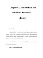
Fig. 7.5. Ideal position for a catheter. Right IJ vein access. Extends with tip inferior to
cavo atrial junction.
164
Access for Dialysis: Surgical and Radiologic Procedures
7
Fig. 7.6. A) Dual lumen catheter showing soft thrombus occluding arterial port from side
holes to tip. B) Split tip catheter showing thrombus plug occluding from most proximal
side hole to tip. There is also some thin fibrin “biofilm” on the catheter. C) Fibrin sheath
causing poor flow (arterial) seen on face. D) Arterial lumen plug of thrombus and fibrin
biofilm removed by “explosive irrigation”.
165
Evaluation and Intervention for Hemodialysis Vascular Access
7
catheters of the split type (example: Medcomp Ash Split-catheter) or the dual-lu-
men catheter (example: the Bard Optiflow) because of their high flow volumes.
These catheters are relatively large bore, are inserted through a single needle punc-
ture site, and tend to have longer patency with fewer catheter infections than sili-
cone rubber tubes in our experience. It must be noted that silicone rubber catheters
are sensitive to degradation by iodine and polyurethane catheters are sensitive to
degradation by alcohol and glycol (Fig. 7.9). Thus iodine solution is the preferred
antiseptic for polyurethane catheters and antibiotic ointment is preferred for sili-
cone rubber catheters. Many other polyurethane catheters are now appearing and
should also give flow in the range of 400 cc per minute.
Even though catheters now have a lumen size that a small balloon catheter or
brush type catheter could be utilized for clearing the lumen of thrombus, the time
and cost efficacy of such maneuvers limit their usefulness both in the dialysis unit
and the interventional suite. From both a functional and cost perspective, catheter
exchange has proven most effective in my practice. If there is no evidence of tract or
Fig. 7.7B. Thick biofilm on a split tip catheter.
Fig. 7.7A. Thin biofilm on a split tip catheter.
166
Access for Dialysis: Surgical and Radiologic Procedures
7
Fig. 7.8. A) Contrast injection shows fibrin sheath
after the split tip catheter has been removed. It
must be destroyed to achieve adequate function
of a new catheter. B) Contrast injection shows fi-
brin sheath remaining after removal of a dual lu-
men catheter. C) 8 mm PTA of the entire sheath
up to the venotomy site destroys sheath. D) Post
fibrin sheath PTA angio shows normal anatomy.
167
Evaluation and Intervention for Hemodialysis Vascular Access
7
Fig. 7.9. Chronic antibiotic ointment use at the exit site of a polyurethane catheter has
caused wall weakness and “catheter aneurysm”.
exit site infection, exchange of a catheter over a guide wire with appropriate
angiographic evaluation for a fibrin sheath is acceptable. If a sheath is visualized, I
use an 8 mm PTA balloon to destroy it. Other methods such as twirling a pigtail
catheter have not been particularly effective for me.
The placement site of tunneled catheters is extremely important in preventing
central venous stenoses. The natural history of catheter access, however, is that cen-
tral venous stenosis can well occur within one year (Fig. 7.10). Subclavian stenoses
associated with dialysis access catheters of any type have been noted in my practice
to occur in as little as 2 weeks (Fig. 7.11). This stenosis develops primarily due to
trauma to the venous wall by the crushing action of the clavicle in apposition with
the first rib during motion. Based on my experience, I strongly feel that the place-
ment of a subclavian catheter in a dialysis patient whose extremity may eventually
be used for a permanent access (or at the same time a new access is placed in the
ipsilateral extremity) is a manifestation of lack of knowledge, inadequate technique
or equipment, or patient neglect, and constitutes malpractice. The subclavian ap-
proach should be used only if there is no plan for further permanent access place-
ment in that extremity and only as a last resort (Fig. 7.12).
I again stress that it is imperative to place tunneled catheters under ultrasonic
localization and fluoroscopic guidance, not only to select the proper vein and avoid
complications associated with the puncture, but also to avoid malposition second-
ary to inadequate catheter length or position of the catheter tip ports into aberrant
veins or in apposition with the right atrial wall (Fig. 7.13).
I now almost always exchange dysfunctional catheters through a new tunnel
because of six procedure-related infections (sepsis) that occurred after exchange over
a guide wire through the same tunnel where the exit site and tunnel showed no
clinical suggestion of infection. Even though this number is well below the accepted
168
Access for Dialysis: Surgical and Radiologic Procedures
7
Fig. 7.10A-C. Natural history of
catheter related stenosis. A) Exter-
nal jugular catheter on the same
side as a new forearm graft present
for 3-4 weeks. B) Veins are still
patent. C) Occlusion present 1 year
post placement.
169
Evaluation and Intervention for Hemodialysis Vascular Access
7
Fig. 7.10D-F. D) Central oc-
clusion treated with 12 mm
PTA. E) Angio post 12 mm
PTA. F) Recurrent occlusion
in 1 month required stent
for prolonged patency.
170
Access for Dialysis: Surgical and Radiologic Procedures
7
Fig. 7.11A-C. A) Central venous oc-
clusion related to 2 weeks presence
of a left subclavian catheter placed
at initial creation of a left forearm
graft. B,C) Central venous 10 mm
PTA.
171
Evaluation and Intervention for Hemodialysis Vascular Access
7
Fig. 7.11D-F. D) Persistent cen-
tral occlusion after PTA. E) Stent
placement and 12 mm PTA. F)
Unrestricted flow post stenting.
172
Access for Dialysis: Surgical and Radiologic Procedures
7
rate of 1-2%, I find it unacceptable to place patients at even this small risk for such
a serious complication. The technique is simple:
• Expose the old catheter central to the cuff through a small incision and
elevate and divide the catheter, being sure to control and clamp the central
fragment.
• Remove the external portion after loosening the cuff by blunt dissection.
• Irrigate the old tunnel and re-apply antiseptic solution to the field.
• Place a guide wire through the central portion of the catheter into the infe-
rior vena cava, being careful not to lose control of the catheter and also to
avoid air embolism.
• Retract the catheter tip to the venotomy site and inject contrast material to
search for a fibrin sheath. If present, destroy the sheath (I use an 8 mm PTA
balloon), create a new subcutaneous tunnel, and place the new catheter into
position over the guide wire.
• Suture in place and dress as usual. (Again refer to Fig. 7.8)
Fig. 7.12. Subclavian catheter should only be placed after extremity is abandoned. Note
relationship of catheter to 1st rib and clavicle accentuating the probability of vein wall
injury. Also note inadequate catheter length.
173
Evaluation and Intervention for Hemodialysis Vascular Access
7
Fig. 7.13. High jugular punctures are often associated with catheter kinks, inadequate
tip position above the C-A junction and overall poor function.
The treatment of infection in tunneled catheters must be coordinated and based
on actual catheter involvement. If blood cultures are positive and there is evidence
of systemic sepsis without evidence of either exit site or tunnel infection, dialysis
access can be maintained by removing the old catheter and replacement with a new
catheter through a new tunnel following the initiation of antibiotic therapy (at least
two IV doses). This exchange is preferably done without the use of a guide wire
during catheter removal. Re-entry can then be done using an angiographic catheter
and guide wire combination when re-accessing the tract from which the old catheter
was removed. This procedure is performed only if the patient has been adequately
covered with antibiotics for two dialysis treatments. The new catheter is then in-
serted as above in the technique for exchange through a new tunnel. Incidentally, if
the tissue in-growth cuff of a tunneled catheter separates during removal, it must be
removed because it is the junction of the exit site with the fibrin sheath of the tunnel
and probably contains significant bacterial inclusions. If left in place, it can cause an
abscess with a foreign body as the nidus (Fig. 7.14).
Local exit site infections can usually be adequately treated by application of an
antiseptic ointment or solution along with systemic antibiotics. Remember that
polyurethane catheters are sensitive to alcohol and glycol, and silicone rubber cath-
eters are sensitive to iodine. If the patient is unresponsive to local antibiotic therapy
over a short time, creation of a new tunnel is an effective way to treat exit-site infec-
tions. Again the technique described above for exchange through a new tunnel is
utilized. Tunnel infection, the equivalent of an abscess, must be aggressively dealt
174
Access for Dialysis: Surgical and Radiologic Procedures
7
with through IV antibiotic therapy, catheter removal, and placement of a new cath-
eter in a different site.
Native AV Fistulae
Although traditional treatment has been surgical revision or abandonment of an
immature or thrombosed fistula to place a graft, I have used endovascular procedures
to treat dialysis patients who have native arteriovenous fistulae (AVF) accesses for
the past ten years. My opinion based on experience and outcomes analysis in treat-
ing immature AVFs, as well as recent literature
14-16
is that abandonment without a
trial of endovascular therapy is a disservice to the patient. These procedures can
promote maturation, improve flow, and achieve long-term usefulness of the access.
Failure of AVFs to mature, defined as inability to support adequate dialysis at four
months after creation, is commonly related to inflow stenosis at or within 5 cm of
the anastomosis, the juxta-anastomotic (J-A) segment. These stenoses cause low in-
flow volume and thus low pressure in the fistula. Arterial flow and elevated pressure
are necessary to promote maturity of the fistula; so in this setting the system does
not develop. These lesions respond well to PTA that restores increased pressure and
volume to the fistula to promote maturation. Long stenoses and small-sized main
veins respond well to serial PTA at 2-3 week intervals (Fig. 7.15).
Sometimes side veins divert flow and pressure from the major draining vein of
the AVF. Although this is usually related to a stenosis further up the fistula, some
diverting side veins persist even after adequate PTA. These side branches can be
occluded by ligation
14
or intravascular coil occlusion,
16
returning all blood coming
into the AVF to the main vein and resulting in ultimate development into a useful
access (Figs. 7.16 and 7.17). In my practice if a fistula does not show signs of pro-
gressive maturation by 2 months, it is studied angiographically to look for lesions
that can be treated to promote maturity. Some developing fistulae are of inadequate
size for use, but respond to serial dilatation by increasingly larger balloons at 2- to 3-
week intervals until adequate size is achieved.
16,18
I consider minimal adequate size
to be 6 mm, and ideal size for dialysis 7-8 mm.
Fig. 7.14. Tissue cuff separation at catheter removal requires foreign body retrieval from
the tunnel.
175
Evaluation and Intervention for Hemodialysis Vascular Access
7
Fig. 7.15A-C. PTA for immature
brachio-basilic transposition
AVF. A,B) Angio shows 6 mm
brachial artery with a 17 cm
long segment 2 mm caliber
firm scarred vein. C) 6 mm PTA
of entire long segment of small
caliber vein.
176
Access for Dialysis: Surgical and Radiologic Procedures
7
Fig. 7.15D-F. D) Central
veins are normal above
the “swing site”. E)
Angio post 6 mm PTA at
“swing site” shows per-
sistent stenosis. F) Swing
site dilated to 8 mm.
177
Evaluation and Intervention for Hemodialysis Vascular Access
7
Problems occur even after maturity has progressed and cannulation begun. If the
vein has been harvested from a deeper location and superficialized after ligation of
numerous side branches, multiple stenoses may be encountered. Common sites for
stenoses in this setting are at the juxta-anastomotic segment, the “swing site”
17
where
the vein has been mobilized from its normal position, and at the site of ligation of
venous side branches (Fig. 7.18). Even though the etiology of these stenoses is un-
sure, it may well be associated with adventitial stripping of the vessel during prepa-
ration for the arteriovenous anastomosis or granulomata associated with surgical
ligatures and electrocautery. The stenoses might even be accentuated by the place-
ment of vascular clamps, however gentle, on the vein at the time of the anastomosis.
Infiltration sites and hypertrophic valves will also result in native vein stenoses. These
are usually within the usable portion of the fistula or the draining veins at a longer
Fig. 7.15G,H. Three week fol-
low up shows a normal
AVF-now in use for 6 months.
G
H
178
Access for Dialysis: Surgical and Radiologic Procedures
7
Fig. 7.16A-C. PTA and side
vein occlusion to promote
maturation. A,B) Angio of im-
mature AVF—note beaded
juxta-anastomotic (J-A) seg-
ment, tiny primary vein and
large diverting side vein. C)
6 mm PTA of J-A segment and
entire draining primary vein.
179
Evaluation and Intervention for Hemodialysis Vascular Access
7
Fig. 7.16D-F. D) 6 mm PTA of J-A segment
and entire draining primary vein. E) Flow
past 6 mm PTA with side vein manually oc-
cluded. F) Fluoro following coil occlusion
of diverting side vein. Note that thrombosis
has not yet been completed. Follow up—
this fistula is now 8 mm caliber and has had
uninterrupted use for 18 months.
180
Access for Dialysis: Surgical and Radiologic Procedures
7
Fig. 7.17A-C. AVF failure to mature: PTA and side
vein occlusion. A,B) Angio of immature AVF with
clinically large side vein compressed. C,D) En-
tire primary vein was dilated to 6 mm. E) Persis-
tent side vein diversion of flow.
181
Evaluation and Intervention for Hemodialysis Vascular Access
7
Fig. 7.17F,G. Two week
post PTA/coil follow up
shows a well matured
AVF ready for use. It has
now been used for 6
months.
distance from the arteriovenous anastomosis and may well be associated with use
before full maturation has occurred. Ineptness of needle cannulation for dialysis
with resultant infiltration and hematoma formation leads to vasospasm, perivascu-
lar scarring and stenosis. Hypertrophic valves and venous divisions also are sites of
stenosis that respond to PTA (Fig. 7.19).
Any of these stenoses may result in the development of flow-diverting side
branches or “stealing veins.” Stealing veins from AVFs divert flow from the main
draining vein and should be ligated or occluded with coils to improve flow through
182
Access for Dialysis: Surgical and Radiologic Procedures
7
Fig. 7.18. Mature brachio-basilic transposition AVF dysfunction related to a “swing site”
stenosis. A) High grade stenosis at the “swing site” of a brachio-basilic transposition AVF
causing decreasing URR after 4 months of good function. B) Stenosis is often resistant
and may require local infiltration and high pressure balloon PTA. C) Successful 8 mm
PTA with a Blue Max catheter. D) Final angio shows an excellent result.
183
Evaluation and Intervention for Hemodialysis Vascular Access
7
Fig. 7.19. AVF dysfunction related to multiple draining vein stenoses. A) Radio-cephalic
AVF with high pressure and low Kt/V. B) Angio shows stenoses in all draining veins. C)
PTA of a vein chosen to be the primary drainage. D) Straight line venous drainage post
PTA. This fistula is now 2 years post procedure with continuous use.
184
Access for Dialysis: Surgical and Radiologic Procedures
7
Fig. 7.20. Central cephalic stenoses are
frequent, but respond to PTA. A) Angio
showing a central cephalic vein steno-
sis. The apparent stenosis of the left in-
nominate vein was not anatomic and
allowed easy passage of an 8 mm bal-
loon. Note that there are no collateral
vessels. B) 8 mm PTA of central cepha-
lic stenosis for 2 minutes at full efface-
ment. C) Final angio shows restored
flow.
the fistula if they persist after adequate PTA,. The first defense against stealing veins
is effective venous PTA to promote primary flow. This may necessitate dilatation to
10 mm. If the vessels continue to steal from the primary venous conduit following
adequate PTA, occlusion can lead to complete maturation or improved function
with optimal flow.
14,16,18
This can be effectively accomplished in smaller vessels (up
to 4-5 mm) by employment of embolization coils (Cook Inc). Care must be exer-
cised in placing these coils to appropriately size the vessels to prevent an emboliza-
tion coil escaping to the lung and yet to achieve permanent occlusion. Vessels of
greater than 6 mm should probably be surgically ligated. This can be done as a
surgical referral or in the interventional suite after definitive localization with a cath-
eter and guide wire, allowing for very focused cut-down and double ligation of a
stealing vein.
185
Evaluation and Intervention for Hemodialysis Vascular Access
7
Central stenoses are noted no more frequently in patients with native fistulae
than in patients with grafts; however, often fistulae (as well as grafts) in which the
cephalic vein is the major draining vein tend to have an area of relative narrowing
near the junction of the cephalic vein to the subclavian vein (Fig. 7.20). This steno-
sis is usually beaded in appearance, 4 to 5 cm long with a variable number and
caliber of stenoses, probably related to hypertrophic venous valves. All of these stenoses
generally respond well to PTA but resistant stenoses may require aggressive
endovascular techniques for resolution.
19
Especially in central lesions, operative in-
terventions often require difficult exposure making endovascular methods the pro-
cedures of choice. Long draining vein stenoses (> 6 cm seen in the draining veins of
both AVF and SBG) were traditionally cause for access abandonment, but they can
be effectively treated by endovascular methods
20
(Fig. 7.21). One should note that
the venous tree is very resilient often giving excellent patency in spite of a terrible
looking initial result (Fig. 7.22).
Thrombosis occurs in only about 10-15% of dysfunctional AVF accesses and
responds well to endovascular recanalization by aspiration thrombectomy
18,21-23
within
72 hours of the clotting episode. After 3 days, thrombectomy is more difficult be-
cause of the adherence of the clot to the wall of the vein. I have performed successful
Fig. 7.21. Angio/PTA long segment venous stenosis. A) Angio showing long segment
stenosis extending 8 mm centrally from the venous anastomosis of an upper arm graft.
B) PTA showing resistant area after dilatation of the rest of the stenosis. C) Full 8 mm
PTA. D) Final angio shows no residual.