DIGITAL CCTV A Security Professional’s Guide phần 7 doc
Bạn đang xem bản rút gọn của tài liệu. Xem và tải ngay bản đầy đủ của tài liệu tại đây (741.75 KB, 32 trang )
Integrating Digital Video
with Other Technologies
11
One of the most interesting aspects of the security industry is the
multifaceted utilization of its products and services. It is com-
parable to the communications industry in its versatility of end
users and uses. Security products and services are found in many
areas—residential, commercial, public service, transportation,
industrial, and military. Not only does the security industry supply
a limitless market, it also combines with many cross markets to
create effi ciency and economy of products and services.
“Systems Integration” became a security industry buzz word
in the late 1990s and post Y2K era. Technology justifi ed the term
by making it possible to interconnect, interface, and integrate sub-
systems of countless varieties, all of which resulted in a marked
increase in security systems sales. Security system dealers and
installers became more commonly known as systems integrators,
and integrated security systems simplifi ed both maintenance and
operations, resulting in a reduced total cost of ownership.
Customers want integration for the advantages it provides,
but barriers like custom and proprietary backbones of existing
179
180 Digital CCTV
equipment have to be considered. Historically, manufacturers
believed having a proprietary protocol protected them from com-
petitive vendors, but today, the opposite is true. Customers are
demanding open architecture and common protocols in order to
reap the benefi ts of integration such as the cost savings incurred
from streamlined business processes and increased effi ciency.
The Security Industry Association (SIA) has identifi ed the
need to clarify systems integration and has created The Systems
Integration Industry Group (SIIG), a group of security profession-
als who are tasked with defi ning integration and establishing
methods and standards for the integration sector. The mission of
SIIG is to create an environment where members of the Security
Industry can gather to communicate the needs facing those who
are active in the integration sector.
INTEGRATED VERSUS INTERFACED
The term integrated is often used loosely to describe the result
when two or more systems are connected to work in conjunction
with each other. Systems are often described as integrated when
they should more accurately be described as interfaced. When a
system is interfaced with another system, an event on one system
can trigger an event on another system. For example, a door
opening on an access control system could trigger a camera to pan,
tilt, and zoom to achieve better coverage, or could change the
record rate of the images from the appropriate camera. See
Figure 11-1.
When a system is integrated, similar triggers have the same
effect, but the integrated system goes a step further. For example,
a card presented at an access control door may cause the appropri-
ate camera to pan, tilt, and zoom for better coverage. It might then
display a live image from that camera along with the badge
holder’s picture for verifi cation. With the interfaced system, the
video would be displayed on one monitor or workstation, while
the access control data is displayed on another. With the inte-
grated system, an operator could potentially deny access through
the door if the person in the live image presenting the card does
Integrating Digital Video with Other Technologies 181
not match the image on fi le as the authorized badge holder. See
Figure 11-2.
Thanks to advances in compression and telecommunications
technologies, remote video can combine several security systems
into one that is both competent and cost effective. The basic remote
system is composed of CCTV cameras installed at locations where
unauthorized intrusion, employee theft, or other criminal activi-
ties may occur. A video transmitter is integrated with the CCTV
system that connects to a receiving site. This connection may be
initiated by the sending or the receiving location, either manually
or by automatic alarm triggers. In the case of an alarm trigger,
strategically placed alarms will alert the receiver of security
breaches and begin providing live video, audio, and in some cases
specifi c data about the incident as it is occurring. An audio feature
can allow a receiver to announce his or her presence and inform
perpetrators that they are being observed and recorded.
Figure 11-1 Interfaced Systems Must Be Monitored Separately
182 Digital CCTV
One of the greatest advantages of integrating video is alarm
verifi cation. When an alarm is activated, the receiver can immedi-
ately view scenes of the alarm location, assess the information, and
take appropriate actions to alleviate the situation. Unnecessary
calls to law enforcement are virtually eliminated. Another distinct
advantage of remote video is that information is stored, providing
documentation of events.
BIOMETRICS
Biometrics is the science and technology of establishing the iden-
tity of an individual by measuring physiological or behavioral
features. Because it can be easily incorporated into surveillance
applications, facial recognition technology for identifi cation and
authentication is experiencing signifi cant growth in both the public
and private sectors.
Figure 11-2 Integrated Systems Are Monitored Through a Single
User Interface
Integrating Digital Video with Other Technologies 183
According to the National Defense University in Washington,
D.C., biometrics refers to the utilization of measurable physiologi-
cal and/or behavioral characteristics to verify the identity of an
individual. In an authentication system, the goal is to confi rm
whether the presented biometrics match the enrolled biometrics of
the same user. Biometrics falls into two categories: physiological
and behavioral. Common physiological biometrics authentication
includes such things as face, eye (retina or iris), fi nger (fi ngertip,
thumb, fi nger length or pattern), palm (print or topography), hand
geometry, and wrist, vein, or thermal images. Behavioral biomet-
rics includes behaviors such as voiceprints, handwritten signatures,
and keystroke/signature dynamics.
These systems identify individuals by comparing known
images to live images from a camera. This means that the camera
system now becomes an integral part of the access control system,
with the live images helping to determine whether access is granted
or denied. By adding multiple cameras, it is then possible, in
theory, to search a building for a specifi c person based upon the
last known location. It is also possible to search crowds of people
for specifi c individuals, such as those stored in terrorist or criminal
databases.
When facial recognition is used for access control, the person
requesting access usually must initiate a comparison, such as by
presenting a card to a card reader. The facial recognition system
then only has to do a “one-to-one” comparison, comparing the live
image to the image on fi le for that card holder. This is also known
as a verifi cation test. When facial recognition is used to monitor
crowds, there is no means of initiation and the system then is
performing a “one-to-many” comparison. The live image of the
person in question must be compared to the entire database of
images to determine if that person is in the database.
A form of thermal imaging called a thermogram reads the
facial heat pattern using an infrared camera. The identifi cation
process begins by capturing the multitude of differences in each
human face. Every human thermal facial image is unique to an
individual and remains consistent from birth through old age.
Even identical twins do not share the same infrared image. The
amount of heat emitted from an individual’s face depends on nine
184 Digital CCTV
factors, including the location of major blood vessels, the skeletal
system thickness, and the amount of tissue, muscle, and fat in the
area. Presently, the most accurate biometric besides thermal is an
iris or retina scanner, which is signifi cantly more expensive than
face, fi nger, or palm recognition systems. It is also harder to fool.
ACCESS CONTROL
To understand the advantages of incorporating video with access
control, it is important to fi rst understand the purpose of the access
control system. Access control is used primarily to allow or deny
access to individuals through controlled and monitored points
within a building. Typically, employees or others who are meant to
have access to certain rooms, areas, or buildings are issued cards
that must be presented at card reader locations to obtain entry.
Typically, this card is used as an identifi cation badge; therefore it
contains employee data and often a photograph of the intended
cardholder. The card also carries information about any restrictions
that may apply, such as when and where entry is authorized.
Access control card systems range from inexpensive, stand
alone systems where the microprocessor is located in the door
without recording capabilities to more expensive systems which
link multiple doors to a central computer. When a card is inserted
into the latter type of access control unit, information from the
card is sent to the computer where validation and recording func-
tions take place. The control of access is performed by a card
reader. Choices of card readers generally include proximity,
weigand, magnetic, or bar code.
Proximity readers, as the name implies, depend upon the
card’s proximity to the reader. The most popular of these readers
work when a card is presented within approximately fi ve inches
from the reader. There are readers that will work from a distance
of three feet. The main advantage to using proximity is the ease
of use—the user need not stop and insert the card into the reader
but merely make sure that the card is within the prescribed ranged
of proximity. In some cases, the card itself may even remain in a
purse or wallet while activating the reader.
Integrating Digital Video with Other Technologies 185
Weigand card technology consists of a series of specially
treated wires, which are embedded in each card. These treated
wires possess unique magnetic properties. When the card passes
through the reader, a sensing coil picks up this unique signature
and transmits it back to the controller.
Magnetic cards are encoded with information that is read by
swiping the magnetic stripe through an appropriate card reader
that senses the code. The process used to make magnetic cards is
relatively simple, consisting of a stripe, which is a coating of iron
oxide or other substance that can be magnetized and demagne-
tized. Some magnetic stripes require more coercivity than others.
Coercivity is the strength of a magnetic fi eld required to record or
change data on the magnetic strip. Everyday magnets can erase a
low-coercivity magnetic stripe; those with high coercivity are vir-
tually non-erasable.
Bar codes are graphical representations of information
encoded within a series of bars and spaces. All bar codes have
certain bar code patterns which tell the reading device when to
start reading the bar code.
The weak link in a standard access control system is often the
lack of verifi cation of who is presenting the card at the reader. If a
card is lost or stolen, the card reader will still function when the card
is presented until it is disabled in the database. Biometric devices
can help to eliminate the possibility of using a stolen card, but they
cannot always verify that an employee is not entering under duress.
Some devices will have the possibility of using a different body part
if under duress, such as using the right eye instead of the left on an
iris recognition reader. If the employee forgets, however, it is pos-
sible to have a false duress read or a missed duress read.
Adding video coverage at access control points can enhance
the system in several ways, depending on how the system is moni-
tored. It is most advantageous when the access control system is
monitored in real time by an active protective force. When this is
the case, an operator can verify that the card being read is in the
possession of the rightful owner and that the cardholder is not
under duress.
With a system that is integrated in this manner, an active card
read will automatically display the proper camera on the monitor
186 Digital CCTV
that shows the door that is being accessed. In addition, the badge
photo that is in the database can be displayed directly next to the
live image, allowing the operator a comparison of the person at
the door and the person authorized to use the card presented.
Video integration can also display live camera views for the
operator in other situations. An attempted entry with an invalid
card or a card that is presented outside of the authorized access
times can cause the appropriate camera to be brought up, allowing
for a live assessment. With an integrated system, it is also possible
to search for specifi c things, such as an individual cardholder.
For example, if an employee is suspected of taking something
such as a laptop, the investigator can search for the associated
employee to see which doors he or she accessed. The investigator
will then have a reduced amount of video to review to see if the
employee can be seen leaving with the item. If the access control
system requires personnel to use a card reader to exit (read in/
read out or anti-pass back confi gurations), the investigator can go
directly to video of the specifi c time that the employee exited.
Many central stations now have the ability to view live video
when an alarm occurs, thus allowing them to make an informed
decision prior to dispatching fi rst responders. If the intrusion
detection system sends an alarm to the central station indicating
that a specifi c entrance has been breached, the operator can access
live video to visually check the situation. If all appears normal, a
review of the time immediately prior to the alarm can be done to
see what may have caused the alarm to be triggered. If the video
still shows nothing unusual, the operator may determine that a
false or nuisance alarm has occurred and choose not to dispatch
authorities. Usually, in this case, an owner or designated contact
is summoned to take appropriate actions.
PERIMETER PROTECTION
The level of protection provided for the protection of a building
or area is determined by the level of risk from intrusion and is
often comprised of several different, complimentary layers of pro-
tection. Perimeter protection can include any combination of things
Integrating Digital Video with Other Technologies 187
like bollards, security fencing, barriers, turnstiles, doors, bars,
grilles, motion detectors, PIR, open ground electronic protection,
or radio frequency intruder detection. The addition of video
surveillance cameras at the perimeter can make a signifi cant con-
tribution towards tightening the whole security system. See
Figure 11-3.
Video technology is commonly used to enhance perimeter
security at correctional facilities. Video technology not only
improves security but also replaces the need to man gun towers
and allows for a reduction in armed perimeter patrols. Electronics
Figure 11-3 Mobile surveillance
tower from P.I.C.S (Portable Intel-
legence Collection System)
188 Digital CCTV
have, in many cases, entirely eliminated the need for towers and
the construction costs associated with them. The strategy has been
to strengthen the entire perimeter with double fences bristling
with electronics and have one or two patrol vehicles (rovers) con-
stantly circling the facility with armed offi cers. As a result, staff
previously assigned to these posts could be shifted to other, more
critical areas.
External active infrared detection has been in use for perim-
eter protection since the late 1920s. These detectors utilize active
infrared beams to detect unauthorized entrance or movements
through an invisible barrier. An active infrared beam, also called
a photoelectric beam, is a sensor that transmits a focused infrared
beam, which is received by a photocell and responds to an inter-
ruption of the beam. Active infrared detection is susceptible to the
false alarm.
Video surveillance installed at many sites using active or
passive infrared detection can be effective in some cases, but
verifi cation of alarms at external sites especially can be hindered
by weather and light conditions. Unless all of the cameras are
equipped with thermal imaging devices, some scenes will neces-
sarily be missed or unidentifi able. Another diffi culty is pinpoint-
ing the exact location of an alarm. With infrared beams capable of
reaching in excess of 200 meters, the result is a potential intruder
located anywhere within a 200 meter zone.
More Digital Video
Applications
12
Law enforcement facilities and correctional institutes are primary
applications for digital video surveillance systems. Video is used
for a variety of purposes in these facilities including security, evi-
dence of brutality against prisoners, videoconferencing, and even
for the provision of medical care via telemedicine technology.
Surveillance levels depend upon the security level of a facility.
These levels are minimum, medium, maximum, and super max.
The higher the level of security, the higher the number of cameras
installed. A super max facility has virtually no area outside of
CCTV view.
Prison visitors are not exempt from the auspices of video
technology. CCTV is often used in prison visiting rooms, for
observing treatment programs, and for auditing mandatory drug
testing of prisoners. This helps to minimize the time required to
clear visitors into and out of correctional facilities as well as reduce
the number of corrections offi cers involved in visitor processing.
When a prison utilizes this type of system, a visitor must pass
an authentication process before being allowed to visit a resident.
189
190 Digital CCTV
During this process, the offi cer may be viewing a live video display
on the PC screen from a CCTV camera. The resident’s information
is displayed, logged on a printed report, and saved in the central
database. The visitor comes to the secured door and keys in their
visitor identifi cation number. A valid number will bring up the
visitor’s image on the correction offi cer’s screen. The screen also
displays a list of approved residents for this visitor. At this time,
an indication is given if visitation privileges have been revoked.
The live video can be compared to the database image displayed
on the screen where remote operation is required. The visitor
states which resident or residents they wish to visit and access is
either confi rmed or denied.
An important aspect of video technology is its impartiality.
Video cannot take sides; it can only display events as they actually
occur. For this reason, video is often the advocate of the victim.
Numerous opportunities are available for using this technol-
ogy in a correctional facility including employee training, business
meetings, court hearings, and parole or deportation hearings.
Videoconferencing and telemedicine technologies reduce the need
to transport dangerous prisoners. Telemedicine programs offer
signifi cant safety, security, and cost advantages to correctional
facilities while being able to provide the services of specialists not
readily available to incarcerated individuals.
Public safety personnel around the nation are starting to use
basic technology tools such as laptops, PDAs, and Automated
External Defi brillators (AEDs). In 2004, Washington, D.C. launched
the nation’s fi rst broadband data network for emergency crews,
an important step toward arming rescuers with the latest com-
munication technology. High-speed wireless networks allow
emergency room doctors to see live video of a patient still in the
ambulance or police helicopters to stream live video from the air
to patrol cars on the ground. The technology enables all rescuers
to talk directly to each other.
Telemedicine
Telemedicine has been defi ned as the use of telecommunications
to provide medical information and services. It may be as simple
More Digital Video Applications 191
as two health professionals discussing a case over the telephone
or as sophisticated as using satellite technology to broadcast a
consultation between providers at facilities in two countries using
videoconferencing equipment. The fi rst is used daily by most
health professionals, while the latter is used by the military, some
large medical centers, and increasingly by correctional facilities.
The University of Texas Medical Branch at Galveston was
one of the original programs to begin providing services to inmates
and sees over 400 patients per month. The foundation of the UTMB
telemedicine network is a scalable, ISDN network operating over
leased T1 lines. Once the technology was in place and real-world
applications identifi ed, the rollout began. One application linked
12 remote sites to UTMB to provide medical care for special-needs
children in areas where medical technology and expertise were
not readily available. The telemedicine solution included a virtual
exam room with a video interface designed to be simple enough
for medical personnel to operate, so that the bulk of their
time could be spent treating patients, not manipulating video
equipment.
Major specialties using the network are neurology, psychia-
try, orthopedics, dermatology, and cardiology. The feedback from
both patients and physicians has been positive, with access to
specialty care and saved travel time cited as the most important
benefi ts of the encounters. Using a variety of specialized patient
cameras, comprehensive patient examinations can be performed,
including diagnostic cardiac echo cardiology and ultrasound
imaging. High-defi nition monitors allow the patient and the phy-
sician to interact as if they were in the same room. With the
primary care physician and the specialist both involved in a
medical consultation, pertinent history can be discussed and inter-
ventional therapies agreed upon.
For correctional facility managers, telemedicine may offer
a means of providing appropriate health care evaluation without
compromising security, reducing costs associated with transport
and protection, and gaining access to physician specialists and
resources unavailable within the prison medical system. Between
September 1996 and December 1996, a leased telemedicine network
was installed to serve four federal prisons to gather information on
192 Digital CCTV
the effectiveness of this technology. One suite, located inside the
penitentiary, served inmates at both the United States Penitentiary
and the Federal Correctional Institution in Allenwood, Pennsylva-
nia, another served inmates at the United States Penitentiary in
Lewisburg, Pennsylvania, and a third served inmates at the Federal
Medical Center (a prison health care facility) in Lexington,
Kentucky. All of these sites were networked for telemedicine with
the Department of Veterans Affairs Medical Center, also in Lexing-
ton. The VA and Federal Medical Centers in Lexington served as
the hubs in this network, providing specialist physicians and other
health care practitioners for remote (telemedical) consultations
with prisoners in the three Pennsylvania prisons.
The purpose was to test the feasibility of remote telemedical
consultations in prisons and to estimate the fi nancial impacts of
implementing telemedicine in other prison systems. One of the
largest for-profi t government and business consulting and research
fi rms in the country, Abt Associates Inc., was contracted to evaluate
the demonstration and estimate the costs and savings associated
with the use of telemedicine in these selected prisons. During the
demonstration, a fi fth mode of care—remote encounters with spe-
cialists via telemedicine—was added to determine whether the
prisons could use telemedicine to overcome local problems in
accessing needed specialists and improve security by averting
travel outside the prison walls. The demonstration was also designed
to supply data on costs and utilization to support a decision about
whether and where to implement telemedicine in other prisons.
In a press release issued in mid-1999, results of a report from
Abt Associates (Cambridge, MA) highlighted the potential for
telemedicine to reduce health care costs in prisons, based on data
gathered in the prison telemedicine demonstration. Specifi cally,
use of telemedicine systems instead of traditional forms of care
(prison staff, in-person clinics, or other health care facilities) was
estimated to save approximately $102.00 per specialist encounter.
Other advantages were quicker access to care (reduced waiting
between referrals and actual consultations) and use of physicians
from outside communities who offer more competitive pricing for
their services.
A telemedicine program at Louisiana State Penitentiary (LSP)
is an outgrowth of the Louisiana State University (LSU) Medical
More Digital Video Applications 193
Center’s telemedicine initiative that began in 1995. Before the tele-
medicine program, approximately 3,000 inmates from LSP were
transported to the secondary and tertiary hospitals for medical-
related reasons during a six month period.
The goals of this project were to reduce the number of inmate
transports from LSP to the secondary and tertiary health care
service centers, reinforce the security parameters and performance
objectives of the Department of Public Safety and Corrections, and
reduce the physical presence of inmates in the general civilian
population served by hospital-based clinics.
Videoconferencing
Digital systems are used to communicate with federal courts to
conduct pre-trial, civil, and mental competency hearings when
it is not desirable to transport a particular inmate to court.
Prison staff is encouraged to use videoconferencing as a means to
reduce travel costs and reduce the risks involved in transporting
prisoners.
Arizona’s popular Sheriff Joe Arpaio made international
news by transmitting live video from the jail onto the Internet for
public viewing. The site provides real life transmissions from the
Maricopa County Sheriff’s Offi ce Madison Street Jail. Maricopa
County is the fourth largest jail system in the world. Housing over
1500 prisoners on average, the Madison Street Jail books an average
of 300 suspects a day. The Offi ce, headed by Sheriff Joe Arpaio, is
known throughout the world for its tough stance on how inmates
are incarcerated and overseen. Sheriff Arpaio is convinced that
using video surveillance and the World Wide Web will deter
crime. It is his hope that the only visit anyone makes to his jail is
the virtual visit provided by the jail cam site.
As with any new procedures or technologies introduced into
use at correctional facilities, video conferencing must pass certain
criteria. The American Society for Testing and Materials (ASTM)
Committee F33 on Detention and Correctional Facilities meets
four times a year in conjunction with the American Jail Association
(AJA) and American Corrections Association (ACA) Conferences
to construct guidelines. The Operational Controls Subcommittee,
194 Digital CCTV
F33.06, has completed the revised “Standard Guide for the Selec-
tion of Operational Security Control Systems”, ASTM F1465-03,
and has started a new work item to develop a guide standard
for the selection of digital video recorders (DVRs). In the future,
this group plans to develop a standard for “Standard Terminology
for Security Control Systems” and a selection guide for “Video
Arraignment and Video Visitation Equipment”.
Law Enforcement and Video The Law Enforcement & Emer-
gency Services Video Association (LEVA) is dedicated to serving
the unique needs of law enforcement and emergency services
professionals who use video. Whether it’s video for production,
training, surveillance, crime scenes or documentation, through its
members, LEVA has established itself as the premiere source for
information, quality training, and networking. Chartered in 1989,
as a volunteer, nonprofi t organization, LEVA serves videogra-
phers and audio/visual specialists from local, state, and federal
law enforcement, fi re, emergency medical, rescue, and other
related public safety agencies throughout the world.
Although LEVA does not endorse any particular manufac-
turer or company product, its members are very knowledgeable
about video equipment and are consulted by their employers and
other public safety agencies for recommendations of potential
purchases of video equipment. Areas of knowledge and expertise
include in-car video systems, surveillance video equipment, crime
scene and documentation equipment, training, and also multime-
dia and production equipment.
Large amounts of people, traffi c, and excitement make sig-
nifi cant public events a challenge for law enforcement. Not to be
left behind the digital movement, Louisville, Kentucky businesses
have begun converting their previously analog systems to the new
digital products. The city sets up even more cameras for the famous
Kentucky Derby festivals and events, which law enforcement use
to monitor crowds and observe traffi c patterns.
Getting three-quarters of a million people in and out of the
venue is a monumental task that requires patience and extensive
planning. The Video Forensics Analysis Unit of the Louisville
More Digital Video Applications 195
Metro Police Department was instrumental in planning and imple-
menting the digital video surveillance aspect of security for the
past few years’ events. With digital video in place, law enforce-
ment can view camera images via microwave, giving them the
ability to direct support to specifi c locations when needed.
The Civil War marked a number of important technological
advances that changed the methods used to gather and commu-
nicate intelligence. Photography was used for the fi rst time. Aerial
photography was also carried out, using hot air balloons. Addi-
tionally, telegraphy was used for the fi rst time though messages
were often intercepted and deciphered. By the time World War I
came along, technology had advanced to include signals intelli-
gence that gained greater importance than in any other war. Tele-
graph and radio messages, in Morse code, were soon vital to the
conduct of war.
Covert Video
Covert video is accomplished fairly simply as almost any normally
occurring piece of home or offi ce equipment can hide a video
camera, including lamps, books, smoke detectors, clocks, and even
stereo components. 2.4 GHz transmitters do better indoors because
the signal frequency is much smaller in width and can move
through walls, in between the studs, and through rebar (which is
in concrete or brick walls). The only limitation is that they cannot
penetrate solid metal walls; the signal frequency will bounce off
or refl ect away. This makes it possible to place a covert camera or
radio (2.4 GHz) in a room with the receiver, antenna, monitor, and
recorder up to 500 feet away. Some types of covert equipment can
be hidden on a person, but generally speaking, microwave signal
frequencies (2.4 GHz) should not be worn on the body.
POLITICAL EVENTS
Nowhere are the efforts against crime and the use of technological
tools, including video, more prevalent than in the protection of
196 Digital CCTV
our nation’s political fi gures. Among its uses for surveillance, live
broadcast, and documentation for the public, video is the star of
political events. During an election year, there are three major
political events where security, technology, and broadcast video
are tested to their limits:
●
Political Party Conventions
●
President and Vice President Candidate Debates
●
Presidential Inauguration
While a specifi c discussion involving the particular elements
of security at these events cannot take place, a general examina-
tion of the signifi cant role of video can occur. When then Texas
Governor George W. Bush received the Republican Party’s nomi-
nation for President of the United States, he was under a protective
umbrella of fi ve high-tech command centers designed to prevent
and respond to terrorist attacks or natural disasters. The Federal
Emergency Management Agency, working with the Secret Service,
the Environmental Protection Agency, and other federal, state,
and local security agencies, established primary command centers
in the Philadelphia region during the convention. Offi cials esti-
mated the total number of people in and around the First Union
Center in Philadelphia at more than 35,000. Given such a large,
compact crowd, planners placed a premium on incident reporting
and timely response coordination, according to the Federal
Response Plan.
Security offi cials began to set up the high-tech monitoring
effort three days before the convention. One of the primary sites
established was the Secret Service’s Multi-Agency Communica-
tion Center (MACC). The EPA and Secret Service offi cials staffed
the MACC around-the-clock during the convention.
From VTRs to VCRs,
DVRs, and NVRs
13
After the ability to create moving images was achieved, the next
challenge was to record the moving images. One of the fi rst men
to attempt a type of electronic recording of information was an
American mechanical engineer named Oberlin Smith, who came
up with the idea of recording electrical signals produced by the
telephone onto a steel wire. Although Smith never actually pursued
his vision, he publicized his ideas in a journal called Electronic
World. Later, Valdemar Poulsen, a Danish telephone engineer and
inventor, patented the fi rst apparatus for magnetic sound record-
ing and reproduction. It recorded, on a wire, the varying magnetic
fi elds produced by a sound. The earliest known attempted use of
magnetic recording to store images was in the late 1920s, by Boris
Ritcheouluff of London. Ritcheouluff designed a picture recorder
based on Poulsen’s machine, developed in Denmark many years
before. Many more video recording concepts followed.
197
198 Digital CCTV
VIDEO TAPE RECORDERS—VTRS
The fi rst practical videotape recorder (VTR) was developed and
sold by Ampex Corporation in 1951. The Ampex VTR captured
live images from television cameras by converting the information
into electrical impulses and saving it onto magnetic tape. VTRs
were similar to reel-to-reel audio tapes, with large spools of multi-
track magnetic tapes measuring 1/2″ to 2″ wide and averaging
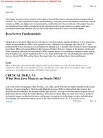
7,000 feet in length. The company demonstrated its Ampex-Mark
IV in April of 1956 at the National Association of Radio and Televi-
sion Broadcasters (NAB) convention. See Figure 13-1. Ampex sold
the fi rst VTR for $50,000 in 1956.
The lack of interchangeability among the very early VTRs
posed a serious problem. The same head assembly used to record
a program had to be used for playback, meaning that the recording
machine head assembly had to be shipped with the tape of evi-
dence in order to view the recorded contents. This problem still
exists in some systems today because many manufacturers use
proprietary compression codecs for their digital recorders.
Figure 13-1 Ampex-Mark IV VTR. Courtesy of Department of
Special Collections and University Archives, Stanford University
Libraries.
From VTRs to VCRs, DVRs, and NVRs 199
VIDEO CASSETTE RECORDERS—VCRS
Magnetic tape recording came into play near the end of World
War II. Though the size of the tape, the speed at which the tape
passed the recording heads, and the way video is written to the
magnetic tape have changed over the years, the basic principles
have remained the same.
The fi rst Betamax VCRs were sold by Sony in 1971. In 1976
Panasonic and JVC introduced its competitor, the Video Home
System (VHS). Originally standard VHS type video cassette record-
ers were used for CCTV applications. A VCR is a device that can
record images from a video camera onto magnetic tape; it can also
play pre-recorded tapes. It is helpful to understand the mechanics
of VCR recorders to also understand the shortcomings. Videotape
is a plastic ribbon impregnated with a magnetizable metal powder.
Before recording, the particles are oriented randomly. During
recording, the video heads create a magnetism that orients the
particles in certain directions converting video signals into mag-
netic patterns on the tape. When the tape is played back, video
heads again pass over the magnetic powder and sense the mag-
netic vibrations and convert these vibrations back into a video
signal.
Video signals consist of millions of electrical vibrations each
second. Each vibration represents a tiny piece of your picture.
Videotape is a ribbon of Mylar with billions of tiny magnets
glued to it with a sophisticated kind of glue called a binder. See
Figure 13-2.
The original magnet material was iron oxide, and so the side
of the tape with magnetic material on it is called the oxide side.
Notice the irregular surface of the oxide coating. When the tape is
being manufactured the mixture of magnetic material and binder
(glue), called slurry, is liquid. The slurry is spread over the Mylar
and allowed to cure or dry. When the slurry cures, some of the
magnetic material protrudes from the surface of the oxide side.
When the video is “written” to the magnetic tape, the video
heads are in intimate contact with tape. In fact, the heads actually
protrude into the surface of the tape, causing a “canoe” in the
Mylar surface. As a result of this contact, the video heads
200 Digital CCTV
experience wear from the friction of the tape rubbing the heads.
See Figure 13-3.
In addition, there is some oxide rubbed off from the tape.
Video headwear is especially high when most of the tape is brand
new because of the irregular surface of the oxide layer. As the
heads “burnish” new tape during recording, the oxide layer surface
is more abrasive than slightly used tape. The surface irregularities
Figure 13-2 Construction of Video Tape
Figure 13-3 Video Head Wear
From VTRs to VCRs, DVRs, and NVRs 201
are literally “sanded” off the oxide surface. As a result, the oxide
layer develops a very smooth surface. After many hours of use,
the worn out heads have to be replaced.
Debris from the oxide and head wear collects around all of
the guides. The result is that the tape transport mechanism must
be cleaned from time to time, or the oxide debris will build up and
cause the edge of the tape to be damaged. If the edge of a tape
becomes suffi ciently damaged, the tape will no longer yield a good
quality of recording and playback. Debris also can clog one or
more of the video heads. This results in loss of recording and large
snowy areas in the picture on playback.
The transport mechanism is complex for a thin, half-inch
ribbon of Mylar, as Figure 13-4 illustrates. Notice that from the
supply reel to the take-up reel, the tape must go through three 180
degree turns. This complex tape path results in a fair amount of
stress on the Mylar that, in turn, results in tape edge damage and
overall quality degradation.
Industrial video recorders differ from consumer recorders in
several ways. For example, they usually operate 24 hours a day
Figure 13-4 Transport Mechanism
202 Digital CCTV
and seven days a week in time lapse mode, which allows a record-
ing of extended periods on video cassettes. High grade video
cassettes are needed to avoid damaging video recording heads.
Industrial grade tapes should be replaced after multiple uses.
DIGITAL VIDEO RECORDERS—DVRS
The biggest selling feature for digital surveillance to date has been
the switch from the video cassette recorder storage to digital
storage. The combination of affordable image compression tech-
nology and large capacity hard disks made the development of
digital video recorders feasible. Digital video storage or digital
video recorders (DVRs) are a practical replacement for analog
VCRs because of the elimination of problems such as poor image
quality from the reuse of tapes, worn out heads, scratches, and
stretching from searching back and forth for a specifi c scene. Wear
and tear aside, no matter how many guidelines are set up for the
management of conventional video tape, one of its biggest down-
falls is the simple action of having to place a tape into the VCR.
A digital video recorder is a stand-alone unit capable of
saving images to a hard disk. DVRs look similar to a standard VCR
in some ways, but that’s where the similarity ends. Because digital
systems are not mechanical like VCRs, factors such as frame speed
and video quality are software adjustable. Unlike the VCR, a
digital video recording device provides clear, sharp images every
time it is played. There are no tapes to store and material does not
deteriorate over time. A digital system allows for auditing of activ-
ity through monitor screen menus and for images to be retrieved
as easily as opening a fi le, using criteria such as date, time, loca-
tion, or camera number. Whatever role the DVR plays, its very
existence declares a system to be digital even though the camera,
transmission, and display technologies may be analog. Digital
video storage allows particular images to be retrieved as easily as
opening a fi le based on criteria such as date, time, location, camera
number, special index numbers, etc. Digital video storage
eliminates the need to store hundreds of space consuming VCR
tapes, and archived material does not deteriorate with time.
From VTRs to VCRs, DVRs, and NVRs 203
The history of the DVR involved a wide variety of technolo-
gies and manufacturers. Costs and availability varied greatly as
well. One of the fi rst companies to deliver a successful product
was Dedicated Micros of Manchester, England. The Dedicated
Micros DVST (Digital Video Storage and Transmission) competed
closely with a Sensormatic remote transmission product.
In the 1990s, motion detection was added to the management
software of the camera or recorder, giving us the fi rst hint of “intel-
ligence” in the systems. There are now literally hundreds of DVR
manufacturers with a wide variety of products and features, many
specializing in solutions by size, location, lighting conditions, or
number of cameras. DVRs are usually scalable and upgradeable
utilizing specifi c software. They typically have video capture cir-
cuits or cards that can process 60, 120, 240, and 480 frames per
second. These numbers represent the total number of frames per
second that can be accommodated for all of the cameras or chan-
nels per system. For example, the 120 frames per second DVR with
16 cameras has an approximate frame rate of 7.5 frames per second.
This means that each camera can be converted at 120/16 or about
7.5 frames per second.
NVR—NETWORK VIDEO RECORDING
New video storage systems work with network attached cameras.
This new technology is very fl exible and provides excellent fea-
tures that allow you to create a complete video surveillance system.
Network Video Recording is a digital video recording solution
that works over a TCP/IP network. IP addressable network
cameras and/or video servers transmit images over a LAN, WAN,
or across the Internet. A NVR automatically receives data from
any IP cameras on a network and store it locally or on remote
storage media. The data can be any combination of video and
audio with hundreds of streams stored on a single server.
The frequently used term client/server describes the rela-
tionship between two computer programs or, in the case of net-
worked video, the NVR and the remote network cameras. The
client makes a service request and the server fulfi lls the request.