OPERATION, MAINTENANCE AND REPAIR OF AUXILIARY GENERATORS Episode 5 ppt
Bạn đang xem bản rút gọn của tài liệu. Xem và tải ngay bản đầy đủ của tài liệu tại đây (696.75 KB, 10 trang )
TM
5-685/NAVFAC
MO-912
0
I5
14
13
12
I
I
IO
9
8
?
6
5
4
3
2
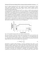
PLOT OF FUEL AND LUBE OIL CONSUMPTION VS. LOAD
ENGINE NO.
19-
Figure 3-l7. Performance data plots.
(c)
“C”
on the chart may indicate a
develop-
ing engine problem.
(d)
“D” on the chart indicates engine gover-
nor positions relative to
"A",
“B”, and
"C”.
b. Engine
overhaul.
An engine consists of struc-
tural parts and moving parts. Structural parts are
those having no movement relative to each other.
They do not involve clearances, adjustments, or lu-
brication. These parts consist of the following: foun-
dation, bedplate, foundation bolts, frames, cylinders
and block, cylinder heads, covers and associated
gaskets, and auxiliary housings. Moving parts are
those that normally require fitting and/or clearance
adjustment. These parts consist of the following:
crankshaft (including journal surfaces, counter-
weights, gears,and flywheels), main bearings,
thrust bearings, camshafts and bearings, connect-
ing rods and bearings, pistons (including rings and
pins), timing gear mechanisms, and auxiliary or
accessory drives. All of these parts are engineered
and designed by the engine manufacturer to per-
form a particular task. When the need to overhaul
an engine is indicated by operational malfunctions
(refer to the troubleshooting table) consult the spe-
cific manufacturer’s literature for instructions.
c.
Overhaul
procedure. Engine overhaul requires
disassembly of the engine. Verify that all engine
parts comply with the manufacturer’s specifications
and tolerances.
(1)
Inspect structural parts as follows:
(a) Foundations for deformation and cracks.
(b)
Bedplate
for cracks and distortion; bear-
ing supports for good condition.
(c) Foundation bolts for tightness and gen-
eral good condition including straightness.
(d)
Frames for cracks, distortion, and gen-
eral good condition.
(e) Cylinders and cylinder blocks for cracks;
water jacket areas for corrosion, scale, and rust;
machined surfaces for smoothness.
(f) Cylinder heads for cracks; water jacket
areas for corrosion, scale, and rust; valve seats for
cracks; machined surfaces for smoothness.
(g)
Covers and gaskets for distortion and
cracks; use satisfactory gaskets only after anneal-
ing; use new seals and gaskets other than copper.
3-25
TM
5-685/NAVFAC
MO-912
PLOT OF MONTHLY PRESSURE CHECKS
100
’
7
I
4
,o
.
’
X
90
I
,
z
60
1 1
I
I I
I
50 COMPRESSION
90
:
60
F
3;
10
2
60
SO
GOVERNOR
g
40
of
30
w
;
20
’
c3
IO
0
f
4
JAM.
FEB.
MAR.
APR.
MAY
JUN.
JUL.
AUG.
SEP.
OCT.
NOV.
OEC.
ENGINE NO._
AVER. LOAD DURING TEST._
KW
4
‘9-
A.
KEY
-
ALONG ENGINE C.L.
ACROSS ENGINE CL.
B.
Figure 3-18. Maintenance data plots.
A) ‘AS-FOUND” PRESSURES,
B)
MEASUREMENTS OF MECHANICAL WEAR INDICATORS.
“.__
(2) Inspect moving parts as follows:
(a) Crankshaft for out-of-alignment condi-
tion; journal surfaces for highly polished condition
and absence of scratches, nicks, etc.; and counter-
weights, gears, and flywheels for proper condition.
Verify that crankshaft complies with manufactur-
er’s requirements. An engine crankshaft is a costly
and vulnerable component. Special care in handling
is required. Accurate alignment is essential to good
engine operation. Removal or installation may re-
quire hoisting. Refer to the manufacturer’s instruc-
tions for details and proper procedures.
(b)
Main be
arings
for highly polished condi-
tion, cracks, deformation and absence of scratches,
nicks, etc.
(c) Thrust bearings for cracks and deforma-
tion; surfaces for smoothness and absence of
scratches and nicks.
(d)
Camshaft
cams and cam faces for worn or
deformed condition; journal surfaces and bearings
for highly polished condition and absence of
scratches, nicks, etc; and cam contours and cam
followers for good condition.
“-_
(e) Connecting rods for cracks or other flaws
by magnaflux or dye penetrant method and for
bending and for parallelism; bearings for highly pol-
ished condition and absence of scratches, nicks,
cracks, and deformation.
(f) Pistons for cracks and warped condition;
verify pistons, rings, and pins comply with manu-
facturer’s requirements; and rings and pins for gen-
eral good condition.
(g)
Timing gear mechanisms for good condi-
tion; backlash for manufacturer’s tolerance require-
ments; and gear teeth for general good condition.
(h) Auxiliary or accessory drives for good op-
erating condition. Consult the specific manufactur-
er’s literature for instructions.
d. Repair parts and supplies. Certain repair
parts and supplies must be available for immediate
use. Refer to specific manufacturer’s literature for
recommendations. The following information is a
general guide:
(1) The follo
wing parts should be renewed at
each: gaskets, rubber sleeves, and seals. Adequate
quantities should be maintained.
(2) The follo
wing parts have a reasonably pre-
dictable service life and require replacement at
pre-
dictable periods: fuel injectors, pumps, governors,
and valves. A one-year supply should be main-
tained.
(3) The follo
wing parts have a normally long
life and, if failure occurs, could disable the engine
for a long period of time: cylinder head, cylinder
liner, piston and connecting rod, gear and chain
drive parts, and oil pressure pump. One item of
TM
5-685/NAVFAC
MO-912
each part for an engine should be available.
e. Parts salvage. Certain parts may be replaced
prior to their failure due to a preventive mainte-
nance program. It may be possible to restore these
parts to specified tolerances. Refer to specific manu-
facturer’s literature for recommendations and in-
structions. The following information is a general
guide:
(1)
Worn pump shafts and cylinder liners may
be built up and machined to specified dimensions.
(2) Grooves in pistons may be machined and
l
oversize rings specified for use.
(3) Press-fitted bushings and bearings may
loosen. The related body part may be machined to a
new dimension and oversize bushings and bearings
fitted.
(4) Worn journals on crankshafts and cam-
shafts may be built up and machined to specified
dimensions.
3-13.
Gas turbine engines.
The following provides a general description of gas
turbine engines used for power generation. Informa-
tion is also provided in paragraph 3-lb of this
manual. For generating electric power, a turboshaft
(shaft turbine engine is used (see fig 3-19). In a
)
turboshaft engine, the turbine provides power in
excess of that required to drive the engine compres-
sor. The excess power is applied as rotary driving
torque available at an output shaft. The power to
drive the output shaft is extracted from the same
turbine that drives the compressor. The turbine is
usually connected through a gearbox to the genera-
tor. The gearbox is used for speed reduction.
3-14.
Gas turbine engine classifications.
a. Pressure and stages. Gas-turbine engines used
for auxiliary power generator sets are classified as
high-pressure-turbine (HPT) or
low-pressure-
turbine (LPT) types. Additionally, the engines are
classified by the number of stages employed in the
turbine design. In general, the more stages used in
the design, the greater the engine torque. All of the
turbine rotor stages in the multi-stage turbine are
connected to a common shaft.
b. Power requirement. For a specified prime
mover power requirement, the engine design can be
either a single-stage, large diameter turbine or an
equivalent small diameter multi-stage turbine.
c. Simple cycle. Most engines are designed to use
natural gas and/or liquid fuel similar to kerosene.
These are called simple-cycle engines.
”
d. Compressor and
combustor.
Most engines have
an axial flow compressor and a cannular or annular
combustion section (combustor).
3-27
TM 5-685/NAVFAC MO-912
3-15. Principles of operation.
a. Components. A typical gas turbine engine con-
sists of a compressor, combustor and turbine (see fig
3-20).
(1)
The compressor is driven by the turbine
through a common shaft. Air enters the compressor
via an inlet duct. The compressor increases the air
pressure and reduces the air volume as it pumps air
to the combustor and through the engine.
(2) Fuel (liq
uidd
and/or natural gas) is delivered
to the combustor by a fuel system consisting of a
manifold, tubes, and nozzles. Electrical igniters in
the combustor provide a spark to ignite the fuel/air
mixture for engine start-up. The igniters are deac-
tivated after start-up has been accomplished. Hot
combustion gases are expelled through the turbine.
(3)
The turbine extracts energy from the hot
-
gases, converting it to rotary power which drives
the compressor and any load, such as a generator.
Exhaust gases are vented via ductwork to the atmo-
sphere.
(4)
The air intake for a gas turbine engine usu-
ally consists of a plenum chamber with a screened
inlet duct opening. The plenum chamber and duct
INLET
DUCT
EXHAUST
I
DUCT
I
Kd
/
SHAFT
GEARBdX
TOR
-
Figure 3-19. Typical gas turbine engine for driving electric power generator.
Figure 3-20. Gas turbine engine,
turboshaft.
3-28
P
TM
5-685/NAVFAC
MO-912
are engine emplacement features that may vary at
connected by tubes to allow flame propagation dur-
different installations. Air entering the duct passes
ing ignition and operation.
3-16. Gas
turbine fuel system.
‘L
through a filter assembly. The filters remove debris
and other material that would otherwise be drawn
into the engine compressor and other operating
ar-
4
eas causing damage. Usually the lowest part of the
plenum is equipped with a drain for removal of
moisture.
z
b. Sequence of euents. Combustion causes an in-
crease in gas temperature proportionate to the
amount of fuel being injected, a moderate increase
in velocity, and a negligible decrease in pressure.
Approximately 25 percent of the compressor’s total
air flow is used for combustion at an air/fuel ratio of
about
15:l.
The remaining 75 percent of compressor
air output is fed to the combustor and to cool
com-
bustor
liners for cooling combustion gases before
they enter the turbine.
System components. The system provides the engine
with the proper amount of fuel to sustain operation.
System components include filters, a fuel manifold,
fuel tubes, and nozzles. Off-engine components in-
clude the fuel control equipment and a supply sys-
tem.
‘“_
(1) The sequence of events during turbine en-
gine start-up and operation is as follows:
(a) Air is drawn into the compressor by ro-
tating the engine. Rotation is accomplished by the
engine starter. The engine is rotated to the speed at
which it becomes self-sustaining.
(b) As the engine shaft is rotated and accel-
erated by the starter, fuel is fed to the combustor.
When the air pressure is high enough, the air/fuel
mixture is ignited by an electrical spark.
(c) The electrical spark is deactivated after
ignition occurs.Since the air/fuel mixture is con-
tinuously fed to the combustor by the turbine and
compressor, and since there is a flame in the
com-
bustor after ignition,engine operation is
self-
sustaining.
(d)
Rotation of th
e
engine by the starter is
necessary after combustion takes place to help ac-
celerate the engine to rated speed. Once the engine
speed has increased to approximately
60 percent of
rated speed, the starter is deactivated.
(e) Gas turbine engines have dual-fuel capa-
bility since they may use either liquid or gaseous
fuel. Generating units with these engines are reli-
able and virtually free of vibration.
(2) Types of combustors. Combustors for gas
turbine engines for generators are either cannular
or annular-type with newer engines usually having
an annular combustor. The annular-type engine is
described in this manual. See figure
3-21 for de-
tails. The annular combustor consists of a
continu-
ous
circular inner and outer casing or shell; the
space between the casings is open. The cannular
combustor consists of inner and outer combustion
casings mounted coaxially around the engine
compressor/rotor shaft. A cluster of burner cans are
located between the two casings. The cans are
inter-
a.
Fuel.
Fuel (liquid and/or natural gas) enters
the tubular fuel manifold ring via the supply sys-
tem. The fuel tubes direct the fuel from the mani-
fold to the fuel nozzles which are mounted in the
fuel swirlers (see fig 3-22 and 3-23). Compressor
discharge air flows radially inward through the
primary swirler in the combustion liner, which
rotates the air circumferentially and mixes it with
the fuel. Air entering radially inward through
the secondary swirler is caused to rotate in the
opposite direction. As the two counter-rotating mix-
tures join, the fuel mixes completely with the air.
This process promotes complete mixing of the fuel
and air and, therefore, more complete burning of
the mixture resulting in less smoke emission and
more uniform temperature distribution within the
combustor.
b. Ignition.
Ignition is accomplished by one or
two igniter plugs. At ignition, the igniters are acti-
vated and fuel is injected into the swirlers. After
ignition, the igniters are deactivated (refer to
para
3-15b( 1)).
3-17. Gas
turbine cooling system.
a. Approximately 25 percent of the air entering a
combustor is mixed with fuel and burned. The re-
maining air is mixed with the products of combus-
tion to reduce the temperature of gases entering the
turbine to a safe operating level. Cooling is accom-
plished by engine airflow.
.
(r
LL
b. Three forms of air cooling of the vanes and
blades are used, either separately or in combina-
tions. The types of cooling are convection, impinge-
ment, and film (see fig 3-24).
(1)
Convection.
For convection cooling, air
flows inside the vanes or blades through serpentine
paths and exits through the blade tip or holes in the
trailing edge. This form of cooling is used in the
area of lower gas temperature (see fig 3-25).
(2) Impingement.
Impingement cooling is a
form of convection cooling, accomplished by direct-
ing cooling air against the inside surface of the
airfoil through small internal high velocity air jets.
Cooling is concentrated at critical sections, such as
leading edges of vanes and blades (see fig 3-26).
3-29
TM
5-685/NAVFAC
MO-912
INNER
COMBUSTION
CASING
COMBUSTION SECTION
~~
CANNULAR
COMBUSTOR
COMBUSTION OUTER CASING
FUEL
DIFF'U
3-30
ANNULAR
COMBUSTOR
Figure 3-21. Typical types of combustors.
ABOVE:
CANNULAR
TYPE; BELOW: ANNULAR
TYPE
TM
5-685/NAVFAC
MO-912
HIGH PRESSURE
TURBINE OUTER CASING
Figure 3 22. Engine combustion section.
(3) Film. Film cooling is a process whereby a
layer of cooling air is maintained between high tem-
perature gases and the external surfaces of the tur-
bine blades and vanes. In general, film cooling is the
most effective type.
3-18. Lubrication system.
a. The lubrication system for a gas turbine en-
gine is usually self-contained with the engine and
supplies oil for lubrication and cooling during en-
gine operation (see fig 3-27). Engine bearings in the
compressor, combustor, and turbine areas (identi-
fied as areas A, B, and C, respectively) are supplied
by the system. System pressure is approximately 75
psi and is usually maintained by a supply and
scav-
enge pump (refer to scavenging in appendix
C).
Most systems include a heat exchanger to cool the
oil and an oil supply tank.
b. On-engine components usually include lubri-
cation supply and scavenge piping, a supply
tem-
perature RTD sensor (resistance temperature detec-
tor), and chip detectors at A, B, and/or C oil
collection sumps. Nozzles are provided for oil
distri-
bution
to bearings. Off-engine components include
flexible oil lines between on-engine and off-engine
components, oil cooler, oil tank, lubrication supply
differential pressure sensor, and lubrication pump.
Oil is supplied by jet or spray to bearings in other
areas via tubes. The engine starter is usually lo-
cated in an accessory gearbox.
(1) A-Sump. Oil for
A
sump components is usu-
ally piped from a gearbox into the sump. Internal
passages and manifolding carry the oil to the
A-sump housing. A double-headed nozzle supplies
oil to the forward bearing and the undercooled car-
bon seal runner for the bearing. The second bearing
is lubricated through oil nozzles mounted on a
power take-off housing. Oil is supplied to the rear
bearings through jets on the forward and aft sides of
the bearing. The carbon seal runner for the bearing
is cooled by oil which has lubricated the power take-
off unit and the compressor forward shaft, and is
then sprayed outward through holes in the shaft.
This oil is then passed through holes at the seal
runner where an oil slinger moves it away from the
carbon seal.
3-31
TM 5-685lNAVFAC MO-912
OUTER SHELL
Figure 3-23. Engine combustion liner.
(2)
B-Sump.
Oil enters the B-sump via a frame
strut and is directed through tubing in the housing
to the mid-engine bearing oil nozzles. Each nozzle
has two jets. One jet supplies oil to the bearing and
the other jet supplies oil to the carbon seal runner
for the bearing.
(3)
C-Sump.
Oil enters the C-sump through a
feed tube and is diverted internally through
manifolding and tubing to the oil nozzles. In many
engines, the
rearmost
nozzle has two heads with
two jets in each head. One set of jets sprays oil on
the bearing. The other set sprays oil on the bearing
locknut which causes the oil to spray on the rear
wall of the C-sump cover and vent collector to cool it
and reduce coking. The adjacent bearing oil nozzle
also usually has two heads with two jets in each.
Two jets direct oil onto the bearing and the others
direct oil to the carbon seal runner for the bearing.
3-32
SCHEMATIC OF TYPICAL
FIRST STAGE TURBINE
INLET STATIONARY VANES
CONVECTION
TM 5-685/NAVFAC MO-912
SC
FI
TU
Figure 3-24. Air cooling modes of turbine vanes and blades.
3-33
TM
5-685/NAVFAC
MO-912
NO
LEADING BLADE
EALER TIP
CAP
~-,
-
INLET HOLES
TRAILING BLADE
SQUEALER TIP
BLADE PLATFORM
CA
AIRFOIL AIR
INLET HOLES
AIR DISCHARGE
HOLES
TRAILING BLADE
MATING
SURFACE
Figure 3-25. Turbine blade cooling air flow.