OPERATION, MAINTENANCE AND REPAIR OF AUXILIARY GENERATORS Episode 7 ppt
Bạn đang xem bản rút gọn của tài liệu. Xem và tải ngay bản đầy đủ của tài liệu tại đây (463.07 KB, 10 trang )
TM
5-685/NAVFAC
MO-912
Frequency = (Speed in
rpm)
(Pairs of poles)
(60
Hertz)
60
e. Power. Power is the term used to describe the
rate at which electric energy is delivered by a gen-
erator and it is usually expressed in watts or kilo-
watts
(lo3 watts).
(1)
Watts. W tt
a s
are units of active or working
power, computed as follows: volts x measured or
apparent amperes x power factor.
(2)
Volt
amperes reactance (Mars). Vars are
units of reactive or nonworking power (1 var = 1
reactive volt-ampere).
(3)
Power factor. Power factor is the ratio of
active or working power divided by apparent power.
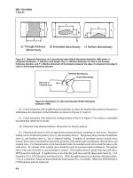
The relationship of apparent power, active power,
and reactive power is shown in figure 4-10. The
hypotenuse represents apparent power, the base
represents active power, and the altitude
power triangle represents reactive power.
of the
Power
factor (the cosine of angle
0)
is a
unitless
number
which can be expressed in per unit or in percentage.
For convenience, kilo
(103)
is often used with the
terms volt- amperes, watts and vars in order to
reduce the number of significant digits.
%
Power Factor =
kW
x 100
kVA
4-8. Exciters.
a. An AC or DC generator requires direct current
to energize its magnetic field. The DC field current
is obtained from a separate source called an exciter.
Either rotating or static-type exciters are used for
AC power generation systems. There are two types
of rotating exciters: brush and brushless. The pri-
mary difference between brush and brushless excit-
ers
ren
is the method used to
t to the generator field
transfer
s. Static
DC exciting
cur-
excitation for the
generator fields is provided in several forms includ-
ing field-flash voltage from storage batteries and
voltage from a system of solid-state components. DC
generators are either separately excited or
self-
excited.
b. Excitation systems in current use include
direct-connected or gear-connected shaft-driven DC
generators, belt-driven or separate prime mover or
motor-driven DC generators, and DC supplied
through static rectifiers.
c. The brush-type exciter can be mounted on the
same shaft as the AC generator armature or can be
housed separately from, but adjacent to, the genera-
tor (see fig 4-2). When it is housed separately, the
exciter is rotated by the AC generator through a
drive belt.
d. The distinguishing feature of the brush-type
generator is that stationary brushes are used to
transfer the DC exciting current to the rotating
generator field. Current transfer is made via rotat-
ing slip rings (collector rings) that are in contact
with the brushes.
e. Each collector ring is a hardened-steel forging
that is mounted on the exciter shaft. Two collector
rings are used on each exciter, each ring is fully
insulated from the shaft and each other. The inner
ring is usually wired for negative polarity, the outer
ring for positive polarity.
f. A rotating-rectifier exciter is one example of
brushless field excitation. In rotating-rectifier excit-
ers, the brushes and slip rings are replaced by a
rotating, solid-state rectifier assembly (see fig 4-4).
The exciter armature, generator rotating assembly,
and rectifier assembly are mounted on a common
shaft. The rectifier assembly rotates with, but is
ANGLE
0
Figure 4-10. Power triangle.
4-8
insulated from, the generator shaft as well as from
each winding.
g. Static exciters contain no moving parts. A por-
tion of the AC from each phase of generator output
is fed back to the field windings, as DC excitations,
through a system of transformers, rectifiers, and
reactors. An external source of DC is necessary for
initial excitation of the field windings. On
engine-
driven generators, the initial excitation may be ob-
tained from the storage batteries used to start the
engine or from control voltage at the switchgear.
4-9.
Characteristics of exciters.
a.
Voltage.
Exciter voltages in common use in-
clude 63 and 125 volts for small units and 250, 375,
or 500 volts for large units. Exciters with normal
self-excitation are usually rated at about 135 per-
cent of rated voltage and a rate buildup of about 125
volts per second. Working range is between 75 and
125 percent of rated exciter voltage.
b. Current. An exciter provides direct current to
energize the magnetic field of an AC generator. Any
DC generator or storage battery may be used as a
field current source.
c. Speed. Speed, in rotating exciters, is related to
generator output voltage. Usually, if magnetic field
intensity is increased (by higher rotating speed),
output voltage of the generator is also increased.
d. Power. Exciter voltage to the magnetic field of
an AC generator is usually set at a predetermined
value. A voltage regulator controls the generator
voltage by regulating the strength of the magnetic
field produced in the exciter.
4-1
0. Field flashing.
a. Field flashing is required when generator volt-
age does not build up and the generating system
(including the voltage regulator) does not have
field-
flash capability. This condition is usually caused by
insufficient residual magnetism in the exciter and
generator fields. In some cases, a generator that has
been out-of-service for an extended period may lose
its residual magnetism and require flashing. Re-
sidual magnetism can be restored by flashing the
field thereby causing a current surge in the genera-
tor. Refer to the voltage regulator manufacturer’s
literature for procedural instructions.
b.
Solid-state components may be included in the
voltage regulator. Perform field flashing according
to the manufacturer’s instructions to avoid equip-
ment damage.
4-1
1. Bearings and lubrication.
a. Location. Several types of bearings, each with
specific lubrication requirements, are used on the
generators. Usually, a generator has two bearings,
TM 5-685/NAVFAC MO-912
one to support each end of the armature shaft. On
some generators, one end of the shaft is supported
by the coupling to the prime mover and one bearing
is used at the other end. The selections of bearing
type and lubrication are based on generator size,
type of coupling to prime mover, and expected us-
age. A generator is usually equipped with either
sleeve or ball bearings which are mounted in end
shields attached to the generator frame.
b. Sleeve bearings. Sleeve bearings are usually
bronze and are lubricated with oil.
(1)
Most u
ni
t
s
with sleeve-type bearings have a
reservoir for the oil and a sight gauge to verify oil
level. Bearings and the reservoir are fully enclosed.
(2)
Distribution of oil to shaft and bearings
from the reservoir is by an oil-slinger ring mounted
on the generator shaft. Rotation of the slinger ring
throws the oil to the top of the bearing. Holes in the
bearing admit oil for lubrication.
(3)
Some units with sleeve-type bearings have
an absorbent fiber packing, saturated with oil,
which surrounds the bearing. Holes in the bearing
admit oil for lubrication.
c. Ball bearings.Ball bearings (or roller-type
bearings) are fully enclosed and lubricated with
grease.
(1) Most units with ball or roller-type bearings
are equipped with a fitting at each bearing to apply
fresh grease. Old grease is emitted from a hoie (nor-
mally closed by a plug or screw) in the bearing
enclosure.
(2) Some units are equipped with
prepacked,
lifetime lubricated bearings.
d. Bearing wear. Noise during generator opera-
tion may indicate worn bearings. If source of noise
is the generator bearing, replacement of the worn
bearing is recommended.
e. Service practices. Service practices for genera-
tors and exciters consist of a complete maintenance
program that is built around records and observa-
tions. The program is described in the
manufactur-
er’s literature furnished with the component. It in-
cludes appropriate analysis of these records.
f. Record keeping. Generator system log sheets
are an important part of record keeping. The sheets
must be developed to suit individual applications
(i.e., auxiliary use).
g. Log sheet data. Log sheets should include sys-
tem starts and stops and a cumulative record of
typical equipment operational items as follows:
(1)
Hours of operation since last bearing lubri-
cation.
(2) Hours ofoperation since last brush and
spring inspection or servicing.
(3) Days since last ventilating and cooling
screen and duct cleaning.
4-9
TM
5-685/NAVFAC
MO-912
h.
Industrial
practices.
Use recognized industrial
practices
as the general guide for generator system
servicing.
i. Reference Literature. The generator system user
should refer to manufacturer’s literature for specific
information on individual units.
4-1
2.
Generator maintenance.
a. Service and troubleshooting. Service consists of
performing basic and preventive maintenance
checks that are outlined below. If troubles develop
or if these actions do not correct a problem, refer to
the troubleshooting table 4-1. Maintenance person-
nel must remember that the manufacturer’s litera-
ture supersedes the information provided herein.
b. Operational check. Check the equipment dur-
ing operation and observe the following indications.
(1)
Unusual noises or noisy operation may in-
dicate excessive bearing wear or faulty bearing
alignment. Shut down and investigate.
(2) Equipment overheats or smokes. Shut
down and investigate.
(3) Equipment brushes spark frequently. Occa-
sional sparking is normal, but frequent sparking
indicates dirty commutator
and/or
brush or brush
spring defects. Shut down and investigate.
c. Preventive maintenance. Inspect the equipment
as described once a month. Maintenance personnel
should make a check list suited to their particular
needs. The actions listed in table 4-l are provided
as a guide and may be modified. Refer to manufac-
turer’s instructions.
Table 4-l. Generator inspection list.
Inspect Check For
Brushes
Commutator
Collector Rings
Insulation
Windings
Bearings
Bearing Housing
Ventilation and cooling
system
Amount of wear, Improper wear, Spring
Tension
Dirt, Amount of wear, Loose leads, Loose
bars
Grooves or wear. Dirt, carbon, and/or
copper accumulation.
(verdigris)
Greenish coating
Damaged insulation. Measure and record
insulation resistance.
Dust and dirt,
connections
Loose windings or
Loose shaft or excessive
endplay.
Vibration (defective bearing)
Lubricant leakage, Dirt or sludge in oil
(sleeve bearings)
Obstruction of air ducts or screens. Loose
or bent fan blades
d.
Troubleshooting.
Perform general trouble-
shooting of the equipment (as outlined in the follow-
ing table) if a problem develops. Refer to the manu-
facturer’s literature for repair information after
diagnosis.
Table 4-2. Generator trouble shooting.
NOISY OPERATION
Cause
Remedy
Unbalanced load or coupling
Balance load and check alignment
misalignment
Air gap not uniform
Center rotor by replacing or
shimming bearings
Coupling loose
Tighten coupling
OVERHEATING
Electrical load unbalanced
Balance load
Open line fuse
Replace line fuse
Restricted ventilation
Clean, remove obstructions
Rotor winding shorted. opened or
Repair or replace defective coil
grounded
Stator winding shorted, opened or
Repair or replace defective coil
grounded
Dry bearings
Lubricate
Insufficient heat transfer of cooler
Verify design flow rate: repair or
unit
replace
NO OUTPUT VOLTAGE
._
Stator coil open or shorted
Repair or replace coil
Rotor coils open or shorted
Repair or replace coils
Shorted sliprings
Repair as directed by manufacturer
Internal moisture (indicated by
Dry winding
low-resistance reading on megger)
Voltmeter defective
Replace
Ammeter shunt open
Replace ammeter and shunt
OUTPUT VOLTAGE UNSTEADY
Poor commutation
Clean slip rings and reseat
brushes
Loose terminal connections
Clean and tighten all contacts
Fluctuating load
Adjust voltage regulator and
governor speed
OUTPUT VOLTAGE TOO HIGH
Over-excited
Adjust voltage regulator
One leg of delta-connected
stator
Replace or repair defective coils
open
FREQUENCY INCORRECT OF FLUCTUATING
Speed incorrect or fluctuating
Adjust speed-governing
device
Table 4-2. Generator trouble shooting-Continued
“C4u
Cause
VOLTAGE HUNTING
Remedy
External
position
field resistance in out
Adjust resistance
Voltage regulator contacts dirty
Clean and reseat contacts
STATOR
OVERHEATS IN SPOTS
Open phase winding
Rotor not centered
Unbalanced circuits
Loose connections or wrong
polarity coil connections
Shorted coil
Cut open coil out of circuit and
replace at first opportunity. Cut and
replace the same coil from other
phases
Realign and replace bearings, if
necessary
Balance circuits
Tighten connections
wrong
connections
or
correct
Cut coil out of circuit and replace
at
first
opportunity
FIELD OVERHEATING
Replace or repair
Shorted
field
coil
Improper ventilation
Remove
ducts
obstruction,clean air
ALTERNATOR PRODUCES SHOCK WHEN TOUCHED
Reversed
field
coil
Static charge
Check polarity. Change coil leads
High-speed
charge
belts build up a static
Connect alternator
ground strip
frame to a
4-1
3.
Insulation testing.
I,
a. The failure of an insulation system is the most
common cause of problems in electrical equipment.
Insulation is subject to many effects which can
cause it to fail; such as mechanical damage, vibra-
tion, excessive heat or cold, dirt, oil, corrosive va-
pors, moisture from processes, or just the humidity
on a muggy day. As pin holes or cracks develop,
moisture and foreign matter penetrate the surfaces
of the insulation, providing a low resistance path for
leakage current. Sometimes the drop in insulation
resistance is sudden, as when equipment is flooded.
Usually, however, it drops gradually, giving plenty
of warning, if checked periodically. Such checks per-
mit planned reconditioning before service failure. If
there are no checks, a motor with poor insulation,
for example, may not only be dangerous to touch
when voltage is applied, but also be subject to burn-
out.
b. The electrical test most often conducted to de-
termine the quality of armature and alternator field
winding insulation is the insulation resistance test.
It is a simple, quick, convenient and nondestructive
TM
5-685/NAVFAC
MO-912
test that can indicate the contamination of insula-
tion by moisture, dirt or carbonization. There are
other tests available to determine the quality of
insulation, but they are not recommended because
they are generally too complex or destructive. An
insulation resistance test should be conducted im-
mediately following generator shutdown when the
windings are still hot and dry. A megohmmeter is
the recommended test equipment.
c. Before testing the insulation, adhere to the fol-
lowing:
(1)
Take th
e
equipment to be tested out of ser-
vice. This involves deenergizing the equipment and
disconnecting it from other equipment and circuits.
(2) If disco
nnecting the equipment from the cir-
cuit cannot be accomplished, then inspect the in-
stallation to determine what equipment is con-
nected and will be included in the test. Pay
particular attention to conductors that lead away
from the installation. This is very important be-
cause the more equipment that is included in a test,
the lower the reading will be, and the true insula-
tion resistance of the apparatus in question may be
masked by that of the associated equipment. It is
always possible, of course, that the insulation resis-
tance of the complete installation will be satisfac-
tory, especially for a spot check. Or, it may be higher
than the range of the megohmmeter, in which case
nothing would be gained by separating the compo-
nents because the insulation resistance of each part
would be still higher.
(3) Test for f
oreign
or induced voltages with a
volt-ohm-milliammeter. Pay particular attention
once again to conductors that lead away from the
circuit being tested and make sure they have been
properly disconnected from any source of voltage.
(4) Large electrical equipment and cables usu-
ally have sufficient capacitance to store a dangerous
amount of energy from the test current. Therefore,
discharge capacitance both before and after any
testing by short circuiting and grounding the equip-
ment and cables under test. Consult manufacturer’s
bulletins and pertinent references to determine,
prior to such shorting or grounding, if a specified
“discharge” or “bleed” or “grounding” resistor should
be used in the shorting/grounding circuit to limit
the magnitude of the discharge current.
(5) Generally, there is no fire hazard in the
normal use of a megohmmeter. There is, however, a
hazard when testing equipment located in inflam-
mable or explosive atmospheres. Slight sparking
may be encountered when attaching test leads to
equipment in which the capacitance has not been
completely discharged or when discharging capaci-
tance following a test. It is therefore suggested that
use of a megohmmeter in an explosive atmosphere
4-11
TM
5-685/NAVFAC
MO-912
be avoided if at all possible. If however testing must
be conducted in an explosive atmosphere, then it is
suggested that test leads not be disconnected for at
least 30 to 60 seconds following a test, so as to allow
time for capacitance discharge.
(6) Do not use a megohmmeter whose terminal
operating voltage exceeds that which is safe to ap-
ply to the equipment under test.
d. To take a spot insulation reading, connect the
megohmmeter across the insulation to be tested and
operate it for a short, specific timed period (60 sec-
onds usually is recommended). Bear in mind also
that temperature and humidity, as well as the con-
dition of your insulation, affect your reading. Your
very first spot reading on equipment, with no prior
test, can be only a rough guide as to how “good” or
“bad” the insulation is. By taking readings periodi-
cally and recording them, you have a better basis of
judging the actual insulation condition. Any persis-
tent downward trend is usually fair warning of
trouble ahead, even though the readings may be
higher than the suggested minimum safe values.
Equally true, as long as your periodic readings are
consistent, they may be OK, even though lower than
the recommended minimum values. You should
make these periodic tests in the same way each
time, with the same test. connections and with the
same test voltage applied for the same length of
time. Table 4-3 includes some general observations
about how you can interpret periodic insulation re-
sistance tests and what you should do with the
results.
e. Another insulation test method is the time re-
sistance method. It is fairly independent of tem-
perature and often can give you conclusive informa-
tion without records of past tests. You simply take
successive readings at specific times and note the
differences in readings. Tests by this method are
sometimes referred to as absorption tests. Test volt-
ages applied are the same as those for the spot
reading test. Note that good insulation shows a con-
tinual increase in resistance over a period of time. If
the insulation contains much moisture or contami-
nants’ the absorption effect is masked by a high
leakage current which stays at a fairly constant
value-keeping the resistance reading low. The
time resistance test is of value also because it is
independent of equipment size. The increase in re-
sistance for clean and dry insulation occurs in the
same manner whether a generator is large or small.
You can therefore compare several generators and
establish standards for new ones, regardless of their
kW ratings.
f. The ratio of two time resistance readings is
called a Dielectric Absorption Ratio. It is useful
in recording information about insulation. If the
ratio is a lo-minute reading divided by a l-minute
reading, the value is called the Polarization Index.
Table 4-4 gives values of the ratio and correspond-
ing relative conditions of the insulation that they
indicate.
Table 4-3. Interpreting insulation resistance test results.
Condition
TEST RESULTS
What to Do
1.
2.
3.
4.
5.
Fair to high values and
well-maintained
Fair to high values, but showing
a constant tendency towards
lower values
Low but well-maintained
So low as to be unsafe
Fair or high values, previously
well-maintained but showing
sudden lowering
No cause for concern
Locate and remedy the cause
check the downward trend
and
Condition is probably all right, but
cause of low values should be
checked
Clean, dry out or otherwise raise
the values before placing
equipment in service (Test wet
equipment while drying out)
Make tests at frequent intervals
until the cause of low values is
located and remedied; or until the
values have become steady at a
lower level but safe for operation;
or until values become so low that
it is unsafe to keep the equipment
in operation
Table
4-4.Condition of insulation indicated
absorption ratios.
*
bY
dielectric
Insulation
Condition
60/30-Second
Ratio
I
Oi
1
-Minute
Polarization
Ratio
Index
Dangerous
Questionable
Good
Excellent
-
1.0 to 1.25
1.4to1.6
Above
1.6**
Less than
1
1.0 to 2
2 to 4
Above
4**
*
These values must be considered tentative and relative; sub-
ject to experience with the time resistance method over a period
of time.
**
In some cases with motors, values approximately 20 percent
higher than shown here indicate a dry brittle winding which will
fail under shock conditions or during starts. For preventive
maintenance, the motor winding should be cleared, treated and
dried to restore winding flexibility.
4-12
TM
5-685/NAVFAC
MO-912
CHAPTER 5
SWITCHGEAR
5-1. Switchgear definition.
Switchgear is a general term covering switching
and interrupting devices that control, meter and
protect the flow of electric power. The component
parts include circuit breakers, instrument trans-
formers, transfer switches, voltage regulators, in-
struments, and protective relays and devices.
Switchgear includes associated interconnections
and supporting or enclosing structures. The various
configurations range in size from a single panel to
an assembly of panels and enclosures (see fig
5-l).
Figure 5-2 contains a diagram of typical switchgear
control circuitry. Switchgear subdivides large blocks
of electric
sions:
power
andperforms
the following
mis-
a. Distributes incoming power between technical
and non-technical loads.
b. Isolates the various loads.
c. Controls auxiliary power sources.
d. Provides the means to determine the quality
and status of electric power.
e. Protects the generation and distribution sys-
tems.
5-2. Types of switchgear.
Voltage classification. Low voltage and medium
voltage switchgear equipment are used in auxiliary
power generation systems. Switchgear at military
installations is usually in a grounded, metal enclo-
sure (see fig
5-l).
Per the Institute of Electrical and
Electronics Engineers (IEEE), equipment rated up
to 1000 volts AC is classed as low voltage. Equip-
ment equal to or greater than 1000 volts but less
than
100,000
volts AC is classed as medium voltage.
a. Low voltage. Major elements of low voltage
switchgear are circuit breakers, potential trans-
formers, current transformers, and control circuits,
refer to paragraph 5-3. Related elements of the
switchgear include the service entrance conductor,
main
ments
box, switches,
indicator lights, and i
.
The serviceentrance conductor
and
nstru-
main
bus (sized as required) are typical heavy duty con-
ductors used to carry heavy current loads.
b.
Medium voltage. Medium voltage switchgear
consists of major and related elements as in low
voltage switchgear. Refer to paragraph
5-4 for de-
tails. Construction of circuit breakers employed in
the two types of switchgear and the methods to
accomplish breaker tripping are the primary differ-
ences. The service entrance conductors and main
bus are typical heavy-duty conductors rated for use
between 601 volts AC and 38,000 volts AC, as re-
quired.
5-3. Low voltage elements.
a. Circuit breakers. Either molded-case or air cir-
cuit breakers are used with low voltage switchgear.
Usually the air circuit breakers have draw-out con-
struction. This feature permits removal of an indi-
vidual breaker from the switchgear enclosure for
inspection or maintenance without de-energizing
the main bus.
(1)
Air circuit breakers. Air circuit breakers are
usually used for heavy-duty, low voltage applica-
tions. Heavy-duty circuit breakers are capable of
handling higher power loads than molded-case
units and have higher current-interrupting capac-
ity. Air circuit breakers feature actuation of contacts
by stored energy which is either electrically or
manually applied. Accordingly, the mechanism is
powered to be put in a position where stored energy
can be released to close or open the contacts very
quickly. Closing or tripping action is applied man-
ually (by hand or foot power) or
electrically
(where
a solenoid provides mechanical force). The me-
chanical force may be applied magnetically. Air
circuit breakers contain power sensor overcurrent
trip devices that detect an overcurrent to the load
and initiate tripping or opening of the circuit
breaker.
(a) Manual circuit breakers employ
spring-
operated, stored-energy mechanisms for operation.
Release of the energy results in quick operation of
the mechanism to open or close the contacts. Oper-
ating speed is not dependent on the speed or force
used by the operator to store the energy.
(b) Fast andpositive action prevents unnec-
essary arcing between the movable and stationary
contacts. This results in longer contact and breaker
life.
(c)
Manual stored-energy circuit breakers
have springs which are charged (refer to the glos-
sary) by operation of the insulated handle. The
charging action energizes the spring prior to closing
or opening of the circuit breaker. The spring, when
fully charged, contains enough stored energy to pro-
vide at least one closing and one opening of the
circuit breaker. The charged spring provides quick
and positive operation of the circuit breaker. Part of
the stored energy, which is released during closing,
may be used to charge the opening springs.
5-1
TM
5-685/NAVFAC MO-912
Figure 5-l. Typical arrangement of metal enclosed switchgear.
(d) Some manual breakers require several
up-down strokes to fully charge. The springs are
released on the final downward stroke. In either of
the manual units, there is no motion of the contacts
until the springs are released.
(e) Electrical quick-make/quick-break break-
ers are operated by a motor or solenoid. In small
units, a solenoid is used to conserve space. In large
sizes, an AC/DC motor is used to keep control-power
requirements low (4 amps at 230 volts).
(f) When the solenoid is energized, the sole-
noid charges the closing springs and drives the
mechanism past the
central/neutral
point in one
continuous motion. Motor-operated mechanisms au-
tomatically charge the closing springs to a predeter-
mined level. When a signal to close is delivered, the
springs are released and the breaker contacts are
closed. The motor or solenoid does not aid in the
closing stroke; the springs supply all the closing
power. There is sufficient stored-energy to close the
contacts under short-circuit conditions. Energy for
opening the contacts is stored during the closing
action.
(g)
A second set of springs opens the contacts
when the breaker receives a trip impulse or signal.
The breaker can be operated manually for mainte-
nance by a detachable handle.
(h) Circuit breakers usually have two or
three sets of contacts: main; arcing; and
intermedi-
5-2
ate. Arcing and intermediate contacts are adjusted
to open after the main contacts open to reduce burn-
ing or pitting of the main contacts.
_-
(i) A typical power sensor for an air circuit
breaker precisely controls the breaker opening time
in response to a specified level of fault current. Most
units function as overcurrent trip devices and con-
sist of a solenoid tripper and solid-state compo-
nents. The solid-state components are part of the
power sensor and provide precise and sensitive trip
signals.
(2) Molded-case circuit breakers. Low current
and low energy power circuits are usually controlled
by molded-case circuit breakers. The trip elements
act directly to release the breaker latch when the
current exceeds the calibrated current magnitude.
Typical time-current characteristic curves for
molded-case circuit breakers are shown in figure
5-3.
(a) Thermal-magnetic circuit breakers have
a thermal bi-metallic element for an inverse
time-
current relationship to protect against sustained
overloads. This type also has an instantaneous mag-
netic trip element for short-circuit protection.
(b) Magnetic trip-only circuit breakers have
no thermal elements. This type has a magnetic trip-
ping arrangement to trip instantaneously, with no
purposely introduced time delay, at currents equal
to, or above, the trip setting. These are used only for
TM
5-685/NAVFAC
MO-912
450 VOLTS, 3PH 60 CPS
GENERATOR BUS
LEGEND
r;!
- AMMETER
- WATTMETER
VM
-
VOLTMETER
F^u
-
GEN. CKT BREAKER
-
FUSE
_
S$
-
FREOUENCY
HETER
- SYNCHROSCOPE
-
TEMPERATURE METER
B-
GE. CKT BREAKER
VR
-
VOLTAGE REGULATOR
PT
-
POTENTIAL TRANSFORMER
CT
-
CURRENT TRANSFORMER
QOV
-
GOVERNOR
Figure 5-2.
Typical
switchgear control circuitry, one-line diagram.
short-circuit protection of motor branch circuits
(1)
Ratings. A PT is rated for the primary volt-
where motor overload or running protection is pro-
age along with the turns (step down) ratio to secure
vided by other elements.
120 VAC across the secondary.
(c)
Non-automatic circuit interrupters have
no automatic overload or short circuit trip elements.
These are used for manual switching and isolation.
Other devices must be provided for short circuit and
overload protection.
b. Potential transformers. A potential trans-
former (PT) is an accurately wound, low voltage loss
instrument transformer having a fixed primary to
secondary “step down” voltage ratio. The PT is
mounted in the high voltage enclosure and only the
low voltage leads from the secondary winding are
brought out to the metering and control panel. The
PT isolates the high voltage primary from the me-
tering and control panel and from personnel. The
step down ratio produces about 120 VAC across the
secondary when rated voltage is applied to the pri-
mary. This permits the use of standard low voltage
meters (120 VAC full scale) for all high voltage cir-
cuit metering and control.
(2)
Application. The primary of potential trans-
formers is connected either line-to-line or
line-to-
neutral, and the current that flows through this
winding produces a flux in the core. Since the core
links the primary and secondary windings, a volt-
age is induced in the secondary circuit (see fig 5-4).
The ratio of primary to secondary voltage is in pro-
portion to the number of turns in the primary and
secondary windings. This proportion produces 120
volts at the secondary terminals when rated voltage
is applied to the primary.
(3) Dot convention. A dot convention is used in
figure 5-5. The dot convention makes use of a large
dot placed at one end of each of the two coils which
are mutually coupled. A current entering the dotted
terminal of one coil produces an open-circuit voltage
between the terminals of the second coil. The volt-
age measured with a positive voltage reference at
the dotted terminal of the second coil.
5-3
TM
5-685/NAVFAC
MO-912
1
CURRENT IN AMPERES AT-
~3.8bJOLTS
CURRENT IN AMPERES AT
13.8K
VOLTS
Figure
5-3. Typical time-current characteristic curve.
a
09
z
08
-
07 uA
r
06
G
01
c. Current transformers. A current transformer
(CT)
is an instrument transformer having low
losses whose purpose is to provide a
f’ixed
primary
to secondary step down current ratio. The primary
to secondary current ratio is in inverse proportion to
the primary to secondary turns ratio. The secondary
winding thus has multiple turns. The CT is usually
5-4
either a toroid (doughnut) winding with a primary
conductor wire passing through the “hole”, or a
sec-
tion of bus bar (primary) around which is wound the
secondary. The bus bar CT is inserted into the bus
being measured. The CT ratio is selected to result
in
a five ampere secondary current when primary
rated current is flowing (see fig 5-4).
-
TM
5-685/NAVFAC
MO-912
POTENT I AL CURRENT
TRANSFORMER
TRANSFORMER
LI
D
V-VOLTMETER
W-WATTMETER
A-AMMETER
Figure 5-4. Instrument transformers, typical applications.
(1)
Ratings. Toroidal
CTs
are rated for the size
of the primary conductor diameter to be surrounded
and the primary to secondary current
(5A)
ratio.
Bus bar type
CTs
are rated for the size of bus bar,
primary voltage and the primary to secondary cur-
rent
5A)
ratio.
(2)
Application. The primary of a CT is either
the line conductor or a section of the line bus. The
secondary current, up to
5A,
is directly proportional
to the line current. The ratio of the primary to
secondary current is inversely proportional to the
ratio of the primary turns to secondary turns.
(3) Safety. A CT, in stepping down the current,
also steps up voltage. The voltage across the second-
ary is at a dangerously high level when the primary
is energized. The secondary of a CT must either be
shorted or connected into the closed metering cir-
cuit. Never open a CT secondary while the primary
circuit is energized.
d. Polarities. When connection secondaries of
PTs
and Cts to metering circuits the correct polarities of
all leads and connections must be in accordance
with the metering circuit design and the devices
connected. Wrong polarity connections will give
false readings and result in inaccurate data, dam-
age and injury. All conductors and terminations
should carry identification that matches schemat-
ics, diagrams and plans used for construction and
maintenance.
e. Control circuits. Switchgear control circuits
provide control
power
for the starting circuit of the
prime movers and the closing and tripping of the
switchgear circuit breakers. Additionally, the con-
trol circuits provide control power to operate the
5-5