Process Planning Episode 5 potx
Bạn đang xem bản rút gọn của tài liệu. Xem và tải ngay bản đầy đủ của tài liệu tại đây (2.58 MB, 40 trang )
Material evaluation and process selection 155
Routing
sheet
Part name: Part no.: Drg. no.:
Quantity: Matl: Mild
steel
Planner: L.E. Hall
Revision
no.: Date: 16/08/01 Page 1 of 1 Order no.:
Op. no. Description Machine tool
10 Cast initial geometry
20 Face to •125 mm
30 Face shoulder
40 Bore Q 100 mm
50 Mill 40 mm wide slot
60 Drill 10 mm diameter, holes • 6
70 Deburr
80 Inspect
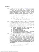
Figure 4.19 Outline process plan for Example 4.2
finished and the shoulder will be faced. The next step will be to mill the slot
and mill the shoulder to a finish. Finally, the holes will have to be drilled. As
there are no heat treatments specified or required and no finishing required,
the part requires no further processing. This outline process plan is illustrated
in the partially completed route sheet in Fig. 4.19.
4.13.3 General guidelines for operations sequencing
The task of operations sequencing cannot be fully addressed until the partic-
ular machine has been selected, which will be covered in Chapter 5. At this
level the number of cuts to produce a certain feature would also be consid-
ered but, again due to the influence of the equipment employed on the num-
ber of cuts required, it cannot be covered in any great detail. However,
general guidelines for operations sequencing developed by Marefat and
Britanik (1998) can be presented. These guidelines depend largely on the
features required to be manufactured and the relationship between them. The
relationships between features help to identify the accessibility of the fea-
tures and therefore the order in which they must be produced. What is meant
by accessibility is that some features may not be able to be produced to the
required specification, for example, size, surface finish, etc. until a related
156
Process Planning
feature is produced. In order to apply these feature-based guidelines, all
features must be categorized as either an external or internal feature:
External feature -
has at least one of their opening faces on the boundary
face of the component and can therefore be accessed directly.
Internal feature -
has all opening faces belonging to other features and
therefore can only be accessed after the production of one of these related
features.
Again, in order to apply these guidelines, the relationships between the
features must be classified as one of the following:
No relationship -
no interaction between features.
Parallel-
features are on the same boundary face.
Perpendicular-
features share a common area.
Contained in-
features are nested, that is, one within the other.
Intersecting-
features share a common volume.
Based on this, a general approach can be followed as follows:
1. Categorize all features as either external or internal features.
2. Address the external features.
3. Re-evaluate the internal features and re-assign them as external and
internal features.
4. Repeat Steps 2 and 3 until all features have been addressed.
In terms of the relationship between two features A and B, there are also a
number of rules that can be applied to determine the sequence in which they
must be produced:
1. If there is no relationship between feature A and B then the order in
which they are produced is not affected.
2. If feature A is external and feature B is internal, then produce feature A
first.
3. If feature A is parallel or perpendicular to feature B, then produce that
with the greatest area.
4. If feature A contains feature B (or vice versa), then produce feature A
first (or vice versa).
5. If the relationship between features A and B is intersecting, then produce
that with the greatest volume first.
Although not sufficient in themselves to help formulate a detailed operations
list that includes the number of cuts, these can be used in conjunction with any
equipment-specific information as a guide for the sequencing of operations for
process planning. The use of these is best illustrated by a worked example.
Material evaluation and process selection
157
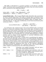
Example 4.3
Consider the simple component illustrated in Fig. 4.20. An
analysis of the geometry, based on the matrix in Fig. 4.6, indicates that this
type of component would be produced by milling the slots and drilling the
holes. The production of both the slots and the holes can be carried out on a
milling machine. Therefore, determine the sequence of operations to produce
these features on a milling machine if the billet is 200 X 120 X 65 mm.
II
200
BO
r Vl
I I
I I
L
I
-I
I-
I I I
I I
I I
I
~, I -,~
I
I
r
HOLES x
4-~
0
020
B5
|
"~q~e ~ f j
x
x$/
Figure 4.20
Orthographic and three-dimensional wire model of part for Example 4.3
158 Process Planning
Solution
The three-dimensional wireframe model illustrates the main features incor-
porated into the component for machining:
Slot 1 - which represents the clearance of material to form the 'step' and is
175 X 120 X 25 mm.
Slot 2- which is the rectangular slot 110 x 80 x 20 mm.
Hole 1 - two through holes 015 x 65 mm.
Hole 2 - two through holes 015 x 40 mm.
Hole 3 - one through hole 020 x 20 mm.
Using the approach outlined above, based on the initial billet size, Slot 1
and Hole 1 are the only external features while the others are internal. This
is because the rest will only be produced after Slot 1 has been produced. As
Slot 1 and Hole 1 are parallel, Slot 1 is produced first because it has the great-
est area of the two. Re-evaluating the features, this means that the Slot 2 and
Hole 2 can now be considered external features along with Hole 1. Again, the
relationship between all features is parallel, except the relationship between
Slot 2 and Hole 3, which is perpendicular. Therefore, this means Slot 2 will
be produced next as it has the greatest area. This now leaves all three holes,
Part name: Part no.:
Revision no.: Date: 17/18/01
Op.
no.
10
20
30
40
50
Description
Mill 175 • 175 x 120 • 25 mm slot
Mill 110 • 80 • 20 mm slot
Drill hole e20 • 20 mm
Drill 2 • holes O15 • 20 mm
Drill 2 • holes O15 • 40 mm
Operations list
Machine Tooling
tool
Drg. no:
Page 1 of 1 Planner: P. Scallan
Speed Feed Set-up Op. Remarks
(rev/min) (mm/min) time time
Figure 4.21 Operations sequence for Example 4.3
Material evaluation and process selection
159
which can now be considered as parallel. Based on this, Hole 3 would be
produced first as it has the greatest area. The remaining two features, Hole 1
and 2 can be produced in any order due to the fact that they have the same
surface area. Therefore, the operations sequence will be as shown in the
operations list in Fig. 4.21.
4.14 Summary
The selection of materials for a component or product is a complex process.
Although there a number of approaches employed, as detailed in Section 4.8,
there are no hard and fast rules that can be followed for optimum material
selection. Furthermore, in the course of this chapter it has been shown that
the material selection process is inextricably linked with process selection
and vice versa. Thus, more organizations take an integrated approach to
product and process design such as that employed in concurrent engineering
or simultaneous engineering.
In terms of process selection, it has been shown that any number of processes
may be used to produce a specific shape or feature. Once these have been iden-
tified there are numerous other factors which come into play and are used for
finxher material evaluation to help in the final process selection. Once selected,
the process then must be placed into some order or sequence for manufactur-
ing. The sequence of operations for each process must then be determined.
However, the process selection will have a bearing on the production equipment
used, the various operations required and the tooling required. Therefore, the
sequencing of specific operations cannot be finalized until the production equip-
ment used is identified, which is the focus for the next chapter.
Case study 4.1: Material
evaluation for a car
alternator*
Introduction
A company who specialize in the design and manufacture of automotive
components has decided to review the basic design of one of their car alter-
nators. As an alternator is a functional component, there is no need to con-
sider the design changes from an aesthetic perspective. In terms of the
materials selection process, the approach is one of modifying an existing
product. The main aim of this is to improve manufacturability and reduce
costs. The first part of this analysis is a thorough evaluation of the present
materials and parts used.
Evaluation of current product design
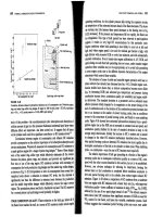
Considering the car altemator shown in Fig. 4.22(a), the parts and material
are assessed against three basic criteria:
Material performance -
there are no specific problems with the performance
of the materials in terms of operation/use and as such they are considered
satisfactory.
* Adapted from Mair (1993).
160
Process Planning
(a) Engine block~/6mm bolt (2 off)
/ Casing
Retainingplate ~ ~ /// ~Endplates(2off)
5mm bolt(3o,)~~~/~/~/'~Armature
Washer ~ ~~I ~ ~ Bearings (2 off)
Lock nuts ~_~_~1~~~_r,~.a.~ ~ \J ./I~Armature spindle
J /U/Ax,, N " " IN'NLJ 4ram bolt (3 off)
,u,,ey ~m,,a stee,) ~ ~'N~/////////////////~
Fan (Aluminium)
J it=IF ',' - ,, ,~- ; " i
,i-]
(b)
~/ ~ Casing and end
Standardized screws
~. ~r, ,
~ plate combined
~-11 ~ n)
~j///N\\I
Fan and pulley ~//'/~ - .~ .~
combined in single ~.,_,
,~ Z/"/~ | ~ ] " Clearance hole
polymer moulding
-
drilled through
Circlip ~ ~_~.~N~
l ~ | /to
ease machining
Splined shaft with ~ Chamfer on shaft
stepped diameters
~/~ ~ ~ ~ to ease assembly
r/'/~L\
\J
Figure 4.22
Alternator assembly (Mair,
1993): (a)
Prototype design,
simplified sketch; (b) assembly redesigned for ease of manufacture
Manufacturing process requirements -
there are three basic categories
of process currently being employed in the manufacture of the alternator.
The first of these is casting for the alternator casing. The second is forming
as the fan is pressed from an aluminium strip. Finally, the remaining parts
for the alternator are manufactured by a mixture of machining processes.
Cost- the
current manufacturing costs for the alternator are unacceptable on
three counts. Firstly, the diversity of materials and processes used is leading
to high manufacturing costs. In particular, the cost for the aluminium strip
and the press tools are unacceptably high. Secondly, the variation and
number of parts is leading to excessively high assembly costs and currently
account for approximately 70 per cent of the total manufacturing costs.
Material evaluation and process selection 161
Finally, also due to the variation and number of parts, the inventory costs are
unacceptably high.
From the above analysis, the focus for the modification of the car alternator
will be on reducing the diversity of materials and processes used and
reducing the number of parts. In summary, the approach will be one of
design simplification.
Evaluation of current product design
In trying to simplify the design as outlined above, three basic approaches can
be taken. These are parts count reduction through combining parts, using
standard parts and basic part design modification.
Parts count reduction
In trying to reduce the number of parts in the design, three basic criteria can
be applied to each part:
1. Does the part need to move relative to the rest of the assembly?
2. Does the part need to be a different material from the rest of the
assembly?
3. Does the part need to be separate for reasons of assembly access or
service and/or repair?
There are three areas where this approach can be employed successfully.
The first of these is the pulley/fan assembly. The pulley is machined from
mild steel and the fan is pressed from aluminium. However, they can be
successfully combined using the above criteria. This single part would be a
polymer moulding. Linked to this, the second area for combining parts is the
locking nuts and washer arrangement for the fan/pulley assembly. These can
be replaced by a single part in the form of a circlip. This will be used to retain
the combined pulley/fan part on a splined shaft as opposed to a threaded
one as at present. The use of the splined shaft/pulley/fan arrangement will
prevent slippage. Finally, the end plate to the right of the assembly
can be combined successfully with the casing assembly according to the
above criteria.
Standardization
All of the above changes will significantly reduce the number of parts
involved and therefore greatly simplify the assembly process. However, there
is a high variety of fasteners used in the design, although combining parts
as detailed above has already eliminated some. To further simplify the
assembly a process of standardization should be used similar to that used in
Case study 3.1. In this case, all remaining screws are standardized to 436 mm
screws of the same length.
The final step in the design simplification is to consider any further
simple design changes that can be made to improve manufacturability. In this
162
Process Planning
case, the part that can be redesigned further is the shaft. Already splined
instead of threaded, the use of a stepped shaft will eliminate the need for
spacers. Furthermore, adding a chamfer to the right-hand side will ease
assembly.
Benefits of design modifications
There are a number of benefits gained from implementing the above design
changes:
Pulley~fan combination -
by designing the pulley and fan as one item, as in
Fig. 4.22(b), a number of cost savings are made:
9 the costs of the mild steel bar and machining for the pulley are saved;
9 the aluminium strip and presswork tooling costs for stamping out the tans
are saved;
9 the costs of holding separate stocks of finished pulleys and fans are
reduced, as are the costs of transporting and assembling the parts since
only one component is now involved.
Lock nuts~washer combination - the
new arrangement reduces the number of
parts and makes assembly much quicker.
Casing/end plate combination -
as well as reducing the number of parts, this
type of design change also reduces the effect of tolerance build up, that is,
the mating faces of the end plate and casing no longer exist therefore machin-
ing of them to within specified sizes is no longer required. The 4 mm nut, bolt
and washer arrangement for holding the assembly together is also no longer
necessary. Thus, cheaper hexagonal-headed screws can be used for assembly,
again reducing material and labour costs. This principle is also applied to the
6 mm bolts holding the alternator to the engine block. From a functional per-
spective, the clamping forces will have to be checked to ensure they remain
adequate and that vibration will not loosen the screws.
Standardization -
by standardizing the size of all the screws to 6 mm dia-
meter and making the lengths the same, savings are again possible by intro-
ducing the opportunity for reduced costs due to high-quantity buying, and by
simplifying storage, material handling and assembly. An additional advan-
tage to the customer is that maintenance is easier since only one size of tool
is now necessary for removal and disassembly.
Shaft modifications -
the need for retaining the plate and associated bolts,
has been removed by adding stepped diameters to the shaft. As well as
removing the need for four parts, assembly of the whole product is much
improved since a 'stacking' sequence can now be followed. Previously the
left-hand end plate assembly would have to be completed as a 'sub-
assembly' before completing the final assembly of the product. Removal of
the retaining plate allows the right-hand section of the alternator to be used
as the 'base' for assembly into which the other components can be stacked
sequentially. This means that only one fixture need be used to hold the work,
and that automatic assembly of the product becomes economically attractive.
Material evaluation and process selection
163
The use of stepped diameters removes the need for the two spacers, again
reducing the number of parts, simplifying assembly, reducing assembly time,
and lowering handling and storage costs. A chamfer has been added to the
right-hand side of the armature spindle to ease assembly.
Summary
Considering the design in Fig. 4.22(a) with that of the re-design in
Fig. 4.22(b), they are very different. The diversity of processes and materials
has been reduced simplifying the manufacturing route. The approaches to the
design simplification will greatly ease assembly, with the parts count being
reduced from 31 to 13. Overall, the manufacturability of the alternator has
been greatly improved. Finally, the cost will be significantly reduced through
simpler assembly.
Discussion points
1. How does the approach taken to the modification of this existing
product compare to that presented in the chapter?
2. In terms of the manufacture of the product, how have the company made
improvements? Comment on the changes in processes and materials.
3. How will the improvements affect the manufacturability of the alternator?
4. In terms of process planning, what will be the result of the design
changes?
5. What kind of approach is the company taking towards the re-design of
this product?
Case study 4.2: Material
and process selection for
car bumpers*
Introduction
In the 1970s, legislation was introduced in the United States and Europe that
meant car manufacturers had to re-design bumper systems. The legislation
demanded that car bumpers be able to withstand collisions at low speeds
without sustaining any permanent damage. One way of meeting these new
legislative requirements, while still having an aesthetically pleasing design
solution, was to use a polymer material instead of the traditional chromium-
electroplated steel. This also was appealing to car manufacturers as they
were trying to introduce more polymers into their products in a bid to reduce
overall weight and therefore improve fuel economy.
As with all design and manufacture problems, the first step towards a
solution is to identify suitable materials that can be processed with existing
manufacturing facilities at the required volume. Therefore, let us consider
the material and process selection process for a typical polymer car bumper.
* Adapted from Edwards and Endean (1990).
164 Process Planning
Materials performance
The first step in developing a solution to the above problem is to specify the
performance parameters of the design in terms of the material performance
requirements. This is identifying the properties required of the material. In
summary, the main material properties of a material for a car bumper are:
9 impact resistance down to -30~
9 adequate rigidity to stay within the dimensional limit of the structure;
9 resistance to ultraviolet degradation and fuel spillage;
9 dimensional stability to prevent distortion over the expected operating
temperature range;
9 ability to be finished to match the surrounding painted metal parts (could
be self-coloured or paintable).
Manufacturing considerations
Once the materials performance has been specified, the manufacturing
parameters must be specified. These include quantity/batch size, weight and
complexity of part, dimensional and geometric accuracy, surface finish and
any other quality requirements. However, the fact that the type of material
has already been specified as a polymer limits the processes that can be used.
Considering this, only four candidate processes can be used:
9 injection moulding;
9 reaction injection moulding (RIM), which is a derivative of injection
moulding that uses reactive fluids;
9 compression moulding;
9 contact moulding.
The four candidates are then compared using the process selection tables
(Tables 4.4 and 4.5). However, to avoid going in to too much detail, the
processes will be compared using a list of general manufacturing considera-
tions derived from the process selection tables. These are cycle time, quality,
cost and production volume. Each of these has been given a rating, with 1 for
the highest value and 4 for the lowest, except for the production volume
which has been stated in units as given in Table 4.11.
Although there is very little difference between all four in terms of quality,
a pattern develops between the others. As the cycle time increases, the costs
increase and the production volume decreases. Therefore, a major factor in
selecting the most appropriate process will be the production volume required.
Material selection
Having gathered all the relevant data on the material property and manu-
facturing requirements, a shortlist of candidate materials can be drawn up.
Material evaluation and process selection
165
TABLE 4.11
Process performance ratings
Process Cycle time Quality
Mins. Rating
Costs Production
volume
E T Rating
Injection 3 4 3
moulding
R/M 6 3 2
Compression 6 2 2
moulding
Contact 60 1 2
moulding
Low
Low
Low-
medium
High
Medium-high High 1 > 10 000
Medium-high Medium 2 > 10 000
Medium-high Medium-high 3 >1000
Low Low 4 1-500
Numerous polymers meet the material performance requirements. However,
the principal commercial polymers are glass-reinforced polyesters and
polyurethanes (polyurethanes can be tailored to do just about anything),
rubber-modified polypropylene, and 'blends' of thermoplastic polyesters and
polycarbonates. From the shortlist, the most suitable material will depend on
the process being used, which in turn, will depend on the production volume
required. However, the best material/process combination can be identified
as follows:
9 contact moulding and polyester-glass-fibre composites;
9 compression moulding and polyester-glass-fibre composites. (The
material, known as sheet moulding compound or SMC, used in this way
consists of sheets of glass fibres of various orientations impregnated with
a low molecular mass polyester and other fillers. The sheets are cut to
size and placed in the mould, and the polymer cross-links rapidly when
heated.);
9 RIM and polyurethanes;
9 injection moulding and polyester-polycarbonate blends, rubber-modified
polypropylene.
Possible solutions
As stated above, the final material/process combination will depend very
much on the production volume required. Therefore, assuming material cost
to be the same, the most suitable solution will depend on the type of product
being manufactured. For example, as contact moulding is only suitable for
low production volumes, the combination of contact moulding and
polyester-glass-fibre composites is suitable only for prototypes and custom
or kit cars. The suitability of all the combinations for particular products is
summarized in Table 4.12.
166 Process Planning
TABLE 4.12 Process and materials for particular product types
Process Mate rial Production Product
volume
Injection
moulding
RIM
Compression
moulding
Contact
moulding
Polyester-glass-fibre High Mass produced
composites models
Polyester-glass-fibre High Mass produced
composites models
Polyurethanes Medium Limited edition and
prestige models
Polyester-polycarbonate Low Prototypes, custom
blends, rubber-modified cars and kit cars
polypropylene
Summary
It is clear from the above that the choice of material and process are inextricably
linked, regardless of which is selected first. What drives the entire material/
process selection is the material and manufacturing performance parameters.
However, with material selection, availability and costs are major considera-
tions and with manufacturing cost is equally important. It is also equally
clear that the type of product and the production volume required have a sig-
nificant influence on both material and process selection. In arriving at a
solution for a problem of the above nature, an iterative selection procedure
should be used. It may also be that a more complex problem may require
much iteration before a satisfactory solution is arrived at as the above prob-
lem has been greatly simplified.
Discussion questions
1. How would you classify the above approach to material and process
selection in terms of the approaches outlined in Section 4.9 in the
chapter?
2. How does this approach compare with that in Case study 4.1?
3. What are the main factors that drive the material/process selection in this
instance?
4. Although there was very little difference in this instance, what other fac-
tor may influence the material/process selection?
5. Can you identify any other factors not mentioned in the case study?
Chapter review
questions
1. What are the four main factors that influence the use of materials in
manufacturing?
Material evaluation and process selection 167
2. What are the four major classifications of material for manufacture?
3. Why are the properties of a material important for its use in
manufacturing?
4. Metals are generally classified as ferrous and non-ferrous. What is
meant by ferrous and non-ferrous metals?
5. Why are carbon steels not classified as an alloy of steel?
6. What are the two types of tool steel?
7. What are the main application areas for ceramics in manufacturing?
8. What are the three main types of polymers used in manufacturing and
how do they differ? Identify one application area for each type.
What are the two basic approaches to material selection?
What is the alternative to the approaches in question 9 and how does
this compare with these?
What are the three main areas focused upon during the material
evaluation? Identify at least three typical considerations for each area.
What is a composite material?
What are the five basic categories of manufacturing processes?
What are the main reasons for considering the use of casting?
What is meant by castability and what are the two major factors that
influence this characteristic?
How do forming and shaping processes compare in terms of
differences and similarities?
What is powder processing and how is it carried out?
What is meant by formability and what are the two major factors that
influence this characteristic?
Why are machining processes the most commonly used of the
manufacturing processes? Give specific reasons.
What are the disadvantages of using machining processes?
What are the main influences on machinability?
What are the three types of joining processes?
What is meant by weldability and what are the major factors that influ-
ence this characteristic?
Why are assembly processes so important to manufacturing?
What are the three classifications of assembly process?
What are the factors that are common to both materials and process
selection?
Manufacturability is also sometimes referred to as workabaility. What
does this mean and how does it relate to the material properties?
.
10.
11.
12.
13.
14.
15.
16.
17.
18.
19.
20.
21.
22.
23.
24.
25.
26.
27.
168 Process Planning
28. How does workability affect the quality of a part?
29. What are the general guidelines for process selection?
30. What are the three main influences on the critical processing factors?
31. When sequencing the manufacturing processes, what are the two
designations for surfaces?
32. What are the six basic stages that all machined parts go through during
manufacture?
33. What are the two classifications for features when sequencing
operations?
34. What are the five basic relationships used between features when
sequencing operations?
35. What are the rules that are applied in the feature-based approach to
operations sequencing?
Chapter review
problems
In Chapter 3, the Chapter review problems 2-5 asked you to identify the
manufacturing process parameters for given parts. Revisit these problems
and develop outline process plans, including operations sequencing, for these
parts using the methods given in Chapter 4. Use Examples 4.1 4.3 as guides
for these exercises.
References and further
reading
Amstead, B.H., Ostwald, EE and Begeman, M.L. (1987). Manufacturing
Processes, 8th edn, Wiley.
Andreasan, M.M., Kahler, S., Lund, T. and Swift, K. (1988). Design for
Assembly, 2nd edn, IFS.
DeGarmo, E.E, Black, J.T. and Kohser, R.A. (1988). Materials and Processes for
Manufacturing, 7th edn, MacMillan.
Demyanyuk, ES. (1963). Technological Principles of Flow Line and Automated
Production, Vol. 1, Pergamon Press.
Dieter, G.E. (1988). Introduction to workability, 'forming and forging', Vol. 14,
ASM Handbook, pp. 363-372, ASM International.
Dieter, G.E. (2000). Engineering Design, 3rd edn, McGraw-Hill.
Edwards, L. and Endean, M., eds (1990). Manufacturing with Materials,
Butterworths.
el Wakil, S.D. (1989). Processes and Design for Manufacturing, Prentice-Hall
International.
Farag, M.M. (1979). Materials and Process Selection in Engineering, Applied
Science Publishers.
Kalpakjian, S. (1995). Manufacturing Engineering and Technology, 3rd edn,
Addison-Wesley.
Ludema, K.C., Caddell, R.M. and Atkins, A.G. (1987). Manufacturing
Engineering - Economics & Processes, Prentice-Hall International.
Mair, G. (1993). Mastering Manufacturing, MacMillan.
Material evaluation and process selection
169
Marefat, M.M. and Britanik, J.M. (1998). Case-based reasoning for three-
dimensional machined components. In
Integrated Product and Process
Development- Methods, Tools and Technologies
(Usher, J.M., Roy, U. and
Parsaei, H.R., eds), Wiley-Interscience.
Schaffer, J.D., Saxena, A., Antolovich, S.D., Sanders, T.H. and Warner, S.B.
(1999).
The Science and Design of Materials,
2nd edn, McGraw-Hill.
Schey, J.A. (1987).
Introduction to Manufacturing Processes,
2nd edn,
McGraw-Hill.
Strong, A.B. (2000).
Plastics - Materials & Processes,
Prentice-Hall.
Swift, K.G. and Booker, J.D. (1997).
Process Selection- From Design to
Manufacture,
Arnold.
Zhang, H. and Alting, L. (1994).
Computerized Manufacturing Process Planning
Systems,
Chapman & Hall.
Relevant standards
International standards
ISO 83: Steel. Charpy impact test (U-notch).
ISO 148: Metallic materials. Charpy pendulum impact test.
ISO 783: Metallic materials. Tensile testing.
ISO 6508: Metallic materials. Rockwell hardness test.
ISO 945: Cast iron.
ISO 185: Grey cast iron. Classification.
ISO 1083: Spheroidal graphite cast iron.
ISO 5922: Malleable cast iron.
ISO 197: Copper and copper alloys.
ISO 209: Wrought aluminium and aluminium alloys. Chemical composition and
form of products.
ISO 6362: Wrought aluminium and aluminium alloys. Extruded rods/bars, tubes
and profiles.
IsofrR 15510: Stainless steel. Chemical composition.
BS EN ISO 4957: Tool steels.
ISO 3685: Tool life testing with single-point turning tools.
British standards
BS 131: Notched bar tests.
BS 860: Table for comparison of hardness scales.
BS 10002: Tensile testing of metallic materials.
BS 970: Specification for wrought steels for mechanical and allied engineering
purposes.
BS EN 10084: Case hardened steels.
BS EN 10085: Nitriding steels.
BS EN 10087: Free cutting steels.
BS EN 10088: Stainless steels.
BS EN 10095: Heat resisting steels and nickel alloys.
BS 1449: Steel plate, sheet and strips.
BS EN 10250: Open steel die forgings for general engineering purposes.
BS EN 1561: Founding. Grey cast iron.
BS EN 1563: Founding. Spheroidal graphite cast iron.
BS EN 12020: Aluminium and aluminium alloys.
BS EN 485: Aluminium and aluminium alloys. Sheet, strip and plate.
170
Process Planning
BS EN 515: Aluminium and aluminium alloys. Wrought products.
BS EN 573: Aluminium and aluminium alloys. Chemical composition for
wrought products.
BS EN 755: Aluminium and aluminium alloys. Extruded rod/bar, tube and
profiles.
BS EN 1652: Copper and copper alloys. Plate, sheet, strip and circles for general
purposes.
BS EN 1982: Specification for copper alloy ingots and copper alloy and
high-conductivity copper castings.
5
Production equipment
and tooling selection
5.1 Introduction
There are many factors to be considered when selecting production equip-
ment for a particular component. The factors considered in this chapter
include the machine's physical size, construction and power. These in turn
will be factors in determining the speeds and feeds available and the maxi-
mum depth of cut the machine is capable of. Another factor is the number
and type of tools available for the production equipment under consideration.
All of the aforementioned factors will ultimately have some effect on the
production rate, batch size and economic viability of the production equip-
ment. Therefore, most of these factors will be incorporated into a five-step
selection procedure for production equipment.
Once the equipment decision has been made, the tooling for the operations
identified previously during the process selection must be selected. In its
broadest sense, the word 'tooling' in manufacturing refers not only to cutting
tools, but also to workholders, jigs and fixtures (also known as durable tool-
ing). However, this chapter will focus firmly on the selection of cutting tools
(also known as consumable tooling) for manufacturing processes and work-
holders, jigs and fixtures will be covered in a subsequent chapter. The justi-
fication for this focus on cutting tools is that the majority of secondary
processing will be material removal processes, more commonly known as
machining. A successful machining process relies on the selection of the
proper cutting tools for the operation at hand and is in fact the most critical
element in the machining system. Among the factors to be considered in
selecting appropriate tooling include workpiece material, type of cut, part
geometry/size, lot size, machining data, machine tool characteristics, cutting
tool materials, tool holding and quality/capability requirements.
5.2 Aims and objectives
The main aim of this chapter is to present a systematic and logical approach to
the selection of the production equipment and tooling to be used for the
processes and operations identified using the approaches outlined in Chapter 4.
On completion of this chapter, you should be able to:
9 identify and describe the main factors in the selection of production
equipment;
9 select appropriate production equipment for a given problem;
9 identify and describe the main factors in the selection of tooling;
9 select appropriate tooling for a given problem.
172
Process Planning
5.3 Production
equipment for specific
processes
As already described in Chapter 4, manufacturing processes can be classified
in five categories, namely casting, shaping/forming, machining, joining and
surface processes. Although assembly processes were also considered in this
chapter, for the purposes of this chapter only the manufacturing processes,
where a part is formed from raw material, will be considered. These five cat-
egories will form the basis upon which to present a summary of the most
commonly used production equipment.
5.3.1 Casting
equipment
There are a large number of casting processes that can be used as highlighted
in the general classification in Chapter 4. However, for the purposes of this
chapter, the scope will be limited to the major casting techniques employed
with steel and aluminium alloys as these are the two most commonly
used engineering materials (Beddoes and Bibby, 1999). It should be noted
that the processes presented are not limited to use only with these materials.
According to the general classification previously presented, casting-
processes can be classified as one of two types, that is, expendable mould or
permanent mould processes.
Expendable mould processes
With expendable mould processes, the moulds are broken in order to remove
the casting. The most basic of these processes is sand casting. It is by far the
oldest and most widely used of all casting processes. A pattern is made in the
shape of the required casting in two halves. The top half (known as the cope)
and the bottom half (known as the drag) are then packed tightly with moist
bonded sand, usually silica sand (SiO2) (Kalpakjian, 1995). The patterns are
then removed and the cope and drag joined. Molten metal is then poured into
the mould via a sprue formed during the sand packing. Once solidified the
mould is broken to release the casting. The process and equipment are illus-
trated in Fig. 5.1. Although often used for producing simple shapes, it is also
widely used for more complex shapes such as engine blocks, manifolds,
machine tool bases, pump housing and cylinder heads.
Shell casting is increasingly being used as it can produce castings with a
high degree of accuracy at a relatively low cost. A metal pattern is made in two
halves. Each pattern is heated and clamped to a box (known as a dump box)
containing sand with a thermosetting resin binder. The dump box is then
inverted and the sand and thermosetting mixture takes the shape of the pattern.
The dump box is then placed in an oven to cure the resin. The oven in most
shell casting processes generally consists of gas-fired burners in a metal box
which swings over the dump box. Once the mixture has cured, the clamp
box is turned round again and the pattern and shell removed from it using the
built-in ejector pins. The two shells are then joined and filled with molten
metal to form the casting. The process and equipment are illustrated in Fig. 5.2.
The last of the expendable casting processes to be considered is invest-
ment casting, sometimes referred to as the lost wax process. A pattern is
formed by injecting wax or thermoplastic resin into a mould or die. The pat-
tern is then removed and coated with a refractory material slurry, usually
Production equipment and tooling selection
173
Figure 5.1
Sand casting process and equipment (Swift and Booker, 1997)
Figure 5.2
Shell casting process and equipment (Swift and Booker, 1997)
some sort of ceramic. Once this coating has been built up to a suitable thick-
ness and dried, the pattern is then melted out. The ceramic mould is then
filled with molten metal to form the casting. When solidification is com-
pleted, the mould is broken to remove the casting.
Permanent mould processes
The major disadvantage of expendable mould processes is the fact that
the mould is not re-used. Although this is acceptable for small quantifies,
174
Process Planning
Figure
5.3
Die casting process and equipment (Swift and Booker, 1997)
permanent mould processes are more suitable for high volume production.
One such process used for high volume production is die casting, also
referred to as pressure die casting. A mould or die is machined from metal.
Molten metal is then poured into the die under pressure. Once solidified, the
die is opened and the part removed. There are two basic variations of pres-
sure die casting, the hot-chamber and the cold-chamber process. The main
difference between them is that a piston is used to trap and force the molten
metal from the shot cylinder in the hot-chamber process, whereas in the cold-
chamber process the molten metal is poured into the shot cylinder (which is
cold) and a plunger used to force the molten metal into the die. Both of these
processes are illustrated in Fig. 5.3.
Another widely used permanent mould casting process is centrifugal cast-
ing. Molten metal is poured into a mould rotating between 300 and 3000rpm
(DeGarmo
et al.,
1988). The rotation forces the molten metal against the walls
of the mould allowing hollow castings to be produced. Finally, the axis of rota-
tion can be either horizontal or vertical. Both are illustrated in Fig. 5.4. In terms
of polymeric casting processes, injection moulding is used more than any other
process to produce thermoplastic products. Granules of raw material are fed
into a pressure chamber via a hopper. While in the hopper the granules are
heated up and forced under pressure into the die. The die remains cool and
therefore the plastic cools as soon as the die is filled. A variation on this is
reaction injection moulding (RIM) where two reactive fluids are forced under
pressure into the die and react to form a thermosetting polymer. The process
and equipment are illustrated in Fig. 5.5.
5.3.2 Shaping/forming equipment
As described in Chapter 4, shaping/forming processes can be broken down into
three categories, namely bulk forming, sheet forming and powder processing.
Production equipment and tooling selection
175
Figure 5.4
Centrifugal casting process and equipment (Swift and Booker, 1997)
Figure 5.5
Injection moulding process and equipment (Swift and Booker, 1997)
Bulk forming
The basic theory behind bulk forming processes was explained in Chapter 4
and, although cold forming is employed, generally hot forming is more com-
mon. The most widely used forming process is hot rolling where material
passes through a number of rollers until the desired shape is achieved.
Hot rolling is used to form steel sections and sheet from large ingots or
176
Process Planning
thick plate, which will generally undergo further processing. Roll-forming
machines, or rolling mills as they are also known, are generally classified
according to spindle support, station configuration and drive system
(Goetsch, 1991). For the purposes of this chapter, we will consider only the
station configuration. Rolling mills usually consist of a number of rollers and
the manner in which they are arranged determines the shape formed. There
are four basic types of roll mill:
Single duty machines-
used for rolling one profile using a particular set of
rollers, which are not easily changed.
Standard machines -
used for different profiles as the rollers are easily
changed.
Side-by-side machine -
used for multiple profiling and has more than one set
of rolling tools mounted at one time (see Fig. 5.6).
Double-high machines -
consists of two sets of rollers at two different levels
on the same frame (see Fig. 5.7).
Of the other hot forming processes, hot forging is probably the most com-
monly used. There are three types of forging namely closed-die, open-die
and impression forging. For open-die forging, equipment can range from a
simple anvil and hammer to huge computer-controlled presses capable of
producing huge forces. Only simple shapes can be produced with open-die
forging. Closed-die forging also uses presses but is capable of more complex
geometry. Particular importance must be paid to the die design to ensure that
it completely fills without creating pressure on the die due to over-filling.
This is overcome in impression forging by including a flash cavity in the die
as illustrated in Fig. 5.8.
Roll tooling
Figure
5.6
Side-by-side rolling machine (Goetsch, 1991)
Production equipment and tooling selection 177
Figure 5.7
Double-high rolling machine (Goetsch, 1991)
Figure 5.8 Forging processes and equipment (Swift and Booker, 1997)
Sheet forming
In terms of sheet metal forming, various processes are used to form
cold rolled sheet. The most common of these are deep drawing, bending and
stretch forming. Roll forming is also used but has been covered under
the heading of bulk processes. Die sets and formers are used and applied
with some force using a press machine of some type. Figure 5.9 illustrates a
typical brake press used for bending, while Fig. 5.10 illustrates roll forming,
deep drawing and stretch forming.
Of the forming processes used for polymers, vacuum forming is widely
used. Also known as thermoforming, the thermoplastic sheet is heated until
Figure 5.9
Brake press and tooling for bending (Swift and Booker, 1997)
Figure 5.10
Forming processes (Swift and Booker, 1997)
Production equipment and tooling selection 179
Figure 5.11 Vacuum forming (Swift and Booker, 1997)
soft. It is then drawn to the mould by means of a vacuum. The mould is usu-
ally at room temperature and this causes the sheet to set upon contacting the
mould as illustrated in Fig. 5.11.
Powder processing
The steps involved in powder processing were previously described in
Section 4.10.3 and these are powder blending, compacting, sintering and
finally secondary processing. In terms of equipment, the compacting requires
a press that can deliver forces in the region of 1.0-1.7 MN. However, most
applications will require a press capacity of less than 1 MN. However, for
large parts, presses with capacities as high as 45 MN may be used.
5.3.3 Machining equipment
Machining processes can be broken down into three types, namely cutting,
abrasive and non-traditional processes. The vast majority of those used will
fall into the cutting category. However, equipment will be considered for all
three categories, albeit briefly.
Cutting processes
Cutting processes can be further classified according to the primary motion,
that is, tool translates, tool rotates and/or workpiece rotates. The main cut-
ting processes where the tool translates are:
Shaping- as the tool translates, the workpiece is fed into the tool. The work-
piece is clamped to the worktable and the worktable feeds across the tool