Science of Everyday Things Vol. 2 - Physics Episode 4 doc
Bạn đang xem bản rút gọn của tài liệu. Xem và tải ngay bản đầy đủ của tài liệu tại đây (831.33 KB, 30 trang )
Torque
87
SCIENCE OF EVERYDAY THINGS
VOLUME 2: REAL-LIFE PHYSICS
case, there is also a place where force is being
applied. On the seesaw, it is the seats, each hold-
ing a child of differing weight. In the realm of
physics, weight is actually a variety of force.
Whereas force is equal to mass multiplied by
acceleration, weight is equal to mass multiplied
by the acceleration due to gravity. The latter is
equal to 32 ft (9.8 m)/sec
2
. This means that for
every second that an object experiencing gravita-
tional force continues to fall, its velocity increas-
es at the rate of 32 ft or 9.8 m per second. Thus,
the formula for weight is essentially the same as
that for force, with a more specific variety of
acceleration substituted for the generalized term
in the equation for force.
As for moment arm, this is the distance from
the pivot point to the vector on which force is
being applied. Moment arm is always perpendi-
cular to the direction of force. Consider a wrench
operating on a lug nut. The nut, as noted earlier,
is the pivot point, and the moment arm is the dis-
tance from the lug nut to the place where the per-
son operating the wrench has applied force. The
torque that the lug nut experiences is the product
of moment arm multiplied by force.
In English units, torque is measured in
pound-feet, whereas the metric unit is Newton-
meters, or N•m. (One newton is the amount of
force that, when applied to 1 kg of mass, will give
it an acceleration of 1 m/sec
2
). Hence if a person
were to a grip a wrench 9 in (23 cm) from the
pivot point, the moment arm would be 0.75 ft
(0.23 m.) If the person then applied 50 lb (11.24
N) of force, the lug nut would be experiencing
37.5 pound-feet (2.59 N•m) of torque.
The greater the amount of torque, the
greater the tendency of the object to be put into
rotation. In the case of a seesaw, its overall design,
in particular the fact that it sits on the ground,
means that its board can never undergo anything
close to 360° rotation; nonetheless, the board
does rotate within relatively narrow parameters.
The effects of torque can be illustrated by imag-
ining the clockwise rotational behavior of a see-
saw viewed from the side, with a child sitting on
the left and a teenager on the right.
Suppose the child weighs 50 lb (11.24 N)
and sits 3 ft (0.91 m) from the pivot point, giving
her side of the seesaw a torque of 150 pound-feet
(10.28 N•m). On the other side, her teenage sister
weighs 100 lb (22.48 N) and sits 6 ft (1.82 m)
from the center, creating a torque of 600 pound-
feet (40.91 N•m). As a result of the torque imbal-
ance, the side holding the teenager will rotate
clockwise, toward the ground, causing the child’s
side to also rotate clockwise—off the ground.
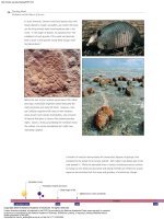
A SEESAW ROTATES ON AND OFF THE GROUND DUE TO TORQUE IMBALANCE
.
(Photograph by Dean Conger/Corbis. Reproduced
by permission.)
set_vol2_sec2 9/13/01 12:33 PM Page 87
Torque
88
SCIENCE OF EVERYDAY THINGS
VOLUME 2: REAL-LIFE PHYSICS
In order for the two to balance one another
perfectly, the torque on each side has to be
adjusted. One way would be by changing weight,
but a more likely remedy is a change in position,
and therefore, of moment arm. Since the teenag-
er weighs exactly twice as much as the child, the
moment arm on the child’s side must be exactly
twice as long as that on the teenager’s.
TORQUE, ALONG WITH ANGULAR MOMENTUM, IS THE LEADING FACTOR DICTATING THE MOTION OF A GYROSCOPE.
HERE, A WOMAN RIDES INSIDE A GIANT GYROSCOPE AT AN AMUSEMENT PARK. (Photograph by Richard Cummins/Corbis. Repro-
duced by permission.)
set_vol2_sec2 9/13/01 12:33 PM Page 88
Torque
Hence, a remedy would be for the two to
switch positions with regard to the pivot point.
The child would then move out an additional 3 ft
(.91 m), to a distance of 6 ft (1.83 m) from the
pivot, and the teenager would cut her distance
from the pivot point in half, to just 3 ft (.91 m). In
fact, however, any solution that gave the child a
moment arm twice as long as that of the teenager
would work: hence, if the teenager sat 1 ft (.3 m)
from the pivot point, the child should be at 2 ft (.61
m) in order to maintain the balance, and so on.
On the other hand, there are many situations
in which you may be unable to increase force, but
can increase moment arm. Suppose you were try-
ing to disengage a particularly stubborn lug nut,
and after applying all your force, it still would not
come loose. The solution would be to increase
moment arm, either by grasping the wrench fur-
ther from the pivot point, or by using a longer
wrench.
For the same reason, on a door, the knob is
placed as far as possible from the hinges. Here the
hinge is the pivot point, and the door itself is the
moment arm. In some situations of torque, how-
ever, moment arm may extend over “empty
space,” and for this reason, the handle of a
wrench is not exactly the same as its moment
arm. If one applies force on the wrench at a 90°-
angle to the handle, then indeed handle and
moment arm are identical; however, if that force
were at a 45° angle, then the moment arm would
be outside the handle, because moment arm and
force are always perpendicular. And if one were
to pull the wrench away from the lug nut, then
there would be 0° difference between the direc-
tion of force and the pivot point—meaning that
moment arm (and hence torque) would also be
equal to zero.
Gyroscopes
A gyroscope consists of a wheel-like disk, called a
flywheel, mounted on an axle, which in turn is
mounted on a larger ring perpendicular to the
plane of the wheel itself. An outer circle on the
same plane as the flywheel provides structural
stability, and indeed, the gyroscope may include
several such concentric rings. Its focal point,
however, is the flywheel and the axle. One end of
the axle is typically attached to some outside
object, while the other end is left free to float.
Once the flywheel is set spinning, gravity has
a tendency to pull the unattached end of the axle
downward, rotating it on an axis perpendicular to
that of the flywheel. This should cause the gyro-
scope to fall over, but instead it begins to spin a
third axis, a horizontal axis perpendicular both to
the plane of the flywheel and to the direction of
gravity. Thus, it is spinning on three axes, and as a
result becomes very stable—that is, very resistant
toward outside attempts to upset its balance.
This in turn makes the gyroscope a valued
instrument for navigation: due to its high degree
of gyroscopic inertia, it resists changes in orienta-
tion, and thus can guide a ship toward its destina-
tion. Gyroscopes, rather than magnets, are often
the key element in a compass. A magnet will point
to magnetic north, some distance from “true
north” (that is, the North Pole.) But with a gyro-
scope whose axle has been aligned with true north
before the flywheel is set spinning, it is possible to
possess a much more accurate directional indica-
tor. For this reason, gyroscopes are used on air-
planes—particularly those flying over the poles—
as well as submarines and even the Space Shuttle.
Torque, along with angular momentum, is
the leading factor dictating the motion of a gyro-
scope. Think of angular momentum as the
momentum (mass multiplied by velocity) that a
turning object acquires. Due to a principle
known as the conservation of angular momen-
tum, a spinning object has a tendency to reach a
constant level of angular momentum, and in
order to do this, the sum of the external torques
acting on the system must be reduced to zero.
Thus angular momentum “wants” or “needs” to
cancel out torque.
The “right-hand rule” can help you to
understand the torque in a system such as the
gyroscope. If you extend your right hand, palm
downward, your fingers are analogous to the
moment arm. Now if you curl your fingers
downward, toward the ground, then your finger-
tips point in the direction of g—that is, gravita-
tional force. At that point, your thumb (involun-
tarily, due to the bone structure of the hand)
points in the direction of the torque vector.
When the gyroscope starts to spin, the vec-
tors of angular momentum and torque are at
odds with one another. Were this situation to
persist, it would destabilize the gyroscope;
instead, however, the two come into alignment.
Using the right-hand rule, the torque vector on a
gyroscope is horizontal in direction, and the vec-
tor of angular momentum eventually aligns with
89
SCIENCE OF EVERYDAY THINGS
VOLUME 2: REAL-LIFE PHYSICS
set_vol2_sec2 9/13/01 12:33 PM Page 89
Torque
90
SCIENCE OF EVERYDAY THINGS
VOLUME 2: REAL-LIFE PHYSICS
it. To achieve this, the gyroscope experiences
what is known as gyroscopic precession, pivoting
along its support post in an effort to bring angu-
lar momentum into alignment with torque. Once
this happens, there is no net torque on the sys-
tem, and the conservation of angular momen-
tum is in effect.
Torque in Complex Machines
Torque is a factor in several complex machines
such as the electric motor that—with varia-
tions—runs most household appliances. It is
especially important to the operation of automo-
biles, playing a significant role in the engine and
transmission.
An automobile engine produces energy,
which the pistons or rotor convert into torque for
transmission to the wheels. Though torque is
greatest at high speeds, the amount of torque
needed to operate a car does not always vary pro-
portionately with speed. At moderate speeds and
on level roads, the engine does not need to pro-
vide a great deal of torque. But when the car is
starting, or climbing a steep hill, it is important
that the engine supply enough torque to keep the
car running; otherwise it will stall. To allocate
torque and speed appropriately, the engine may
decrease or increase the number of revolutions
per minute to which the rotors are subjected.
Torque comes from the engine, but it has to
be supplied to the transmission. In an automatic
transmission, there are two principal compo-
nents: the automatic gearbox and the torque con-
verter. It is the job of the torque converter to
transmit power from the flywheel of the engine
to the gearbox, and it has to do so as smoothly as
possible. The torque converter consists of three
elements: an impeller, which is turned by the
engine flywheel; a reactor that passes this motion
on to a turbine; and the turbine itself, which
turns the input shaft on the automatic gearbox.
An infusion of oil to the converter assists the
impeller and turbine in synchronizing move-
ment, and this alignment of elements in the
torque converter creates a smooth relationship
between engine and gearbox. This also leads to
an increase in the car’s overall torque—that is, its
turning force.
ACCELERATION: A change in veloci-
ty over a given time period.
EQUILIBRIUM: A situation in which
the forces acting upon an object are in
balance.
FORCE: The product of mass multi-
plied by acceleration.
INERTIA: The tendency of an object in
motion to remain in motion, and of an
object at rest to remain at rest.
MASS: A measure of inertia, indicating
the resistance of an object to a change in its
motion—including a change in velocity.
MOMENT ARM: For an object experi-
encing torque, moment arm is the distance
from the pivot or balance point to the vec-
tor on which force is being applied.
Moment arm is always perpendicular to
the direction of force.
SPEED: The rate at which the position
of an object changes over a given period of
time.
TORQUE: The product of moment
arm multiplied by force.
VECTOR: A quantity that possesses
both magnitude and direction. By contrast,
a scalar quantity is one that possesses only
magnitude, with no specific direction.
VELOCITY: The speed of an object in a
particular direction.
WEIGHT: A measure of the gravitation-
al force on an object; the product of mass
multiplied by the acceleration due to
gravity.
KEY TERMS
set_vol2_sec2 9/13/01 12:33 PM Page 90
Torque
Torque is also important in the operation of
electric motors, found in everything from vacu-
um cleaners and dishwashers to computer print-
ers and videocassette recorders to subway sys-
tems and water-pumping stations. Torque in the
context of electricity involves reference to a num-
ber of concepts beyond the scope of this discus-
sion: current, conduction, magnetic field, and
other topics relevant to electromagnetic force.
WHERE TO LEARN MORE
Beiser, Arthur. Physics, 5th ed. Reading, MA: Addison-
Wesley, 1991.
Macaulay, David. The New Way Things Work. Boston:
Houghton Mifflin, 1998.
“Rotational Motion.” Physics Department, University of
Guelph (Web site).
< />(March 4, 2001).
“Rotational Motion—Torque.” Lee College (Web site).
< />Courses/LabManual/2b/2b.html> (March 4, 2001).
Schweiger, Peggy E. “Torque” (Web site).
< />mot.html> (March 4, 2001).
“Torque and Rotational Motion” (Web site).
< />.asp> (March 4, 2001).
91
SCIENCE OF EVERYDAY THINGS
VOLUME 2: REAL-LIFE PHYSICS
set_vol2_sec2 9/13/01 12:33 PM Page 91
93
SCIENCE OF EVERYDAY THINGS
real-life Physics
FLUID MECHANICS
AERODYNAMICS
BERNOULLI’S PRINCIPLE
BUOYANCY
FLUID MECHANICS
FLUID MECHANICS
set_vol2_sec3 9/13/01 12:35 PM Page 93
95
SCIENCE OF EVERYDAY THINGS
VOLUME 2: REAL-LIFE PHYSICS
FLUID MECHANICS
Fluid Mechanics
CONCEPT
The term “fluid” in everyday language typically
refers only to liquids, but in the realm of physics,
fluid describes any gas or liquid that conforms to
the shape of its container. Fluid mechanics is the
study of gases and liquids at rest and in motion.
This area of physics is divided into fluid statics,
the study of the behavior of stationary fluids, and
fluid dynamics, the study of the behavior of mov-
ing, or flowing, fluids. Fluid dynamics is further
divided into hydrodynamics, or the study of
water flow, and aerodynamics, the study of air-
flow. Applications of fluid mechanics include a
variety of machines, ranging from the water-
wheel to the airplane. In addition, the study of
fluids provides an understanding of a number of
everyday phenomena, such as why an open win-
dow and door together create a draft in a room.
HOW IT WORKS
The Contrast Between Fluids
and Solids
To understand fluids, it is best to begin by con-
trasting their behavior with that of solids.
Whereas solids possess a definite volume and a
definite shape, these physical characteristics are
not so clearly defined for fluids. Liquids, though
they possess a definite volume, have no definite
shape—a factor noted above as one of the defin-
ing characteristics of fluids. As for gases, they
have neither a definite shape nor a definite vol-
ume.
One of several factors that distinguishes flu-
ids from solids is their response to compression,
or the application of pressure in such a way as to
reduce the size or volume of an object. A solid is
highly noncompressible, meaning that it resists
compression, and if compressed with a sufficient
force, its mechanical properties alter significant-
ly. For example, if one places a drinking glass in a
vise, it will resist a small amount of pressure, but
a slight increase will cause the glass to break.
Fluids vary with regard to compressibility,
depending on whether the fluid in question is a
liquid or a gas. Most gases tend to be highly com-
pressible—though air, at low speeds at least, is
not among them. Thus, gases such as propane
fuel can be placed under high pressure. Liquids
tend to be noncompressible: unlike a gas, a liquid
can be compressed significantly, yet its response
to compression is quite different from that of a
solid—a fact illustrated below in the discussion
of hydraulic presses.
One way to describe a fluid is “anything that
flows”—a behavior explained in large part by the
interaction of molecules in fluids. If the surface
of a solid is disturbed, it will resist, and if the
force of the disturbance is sufficiently strong, it
will deform—as for instance, when a steel plate
begins to bend under pressure. This deformation
will be permanent if the force is powerful
enough, as was the case in the above example of
the glass in a vise. By contrast, when the surface
of a liquid is disturbed, it tends to flow.
MOLECULAR BEHAVIOR OF
FLUIDS AND SOLIDS.
At the molecu-
lar level, particles of solids tend to be definite in
their arrangement and close to one another. In
the case of liquids, molecules are close in prox-
imity, though not as much so as solid molecules,
and the arrangement is random. Thus, with a
glass of water, the molecules of glass (which at
set_vol2_sec3 9/13/01 12:36 PM Page 95
Fluid
Mechanics
96
SCIENCE OF EVERYDAY THINGS
VOLUME 2: REAL-LIFE PHYSICS
relatively low temperatures is a solid) in the con-
tainer are fixed in place while the molecules of
water contained by the glass are not. If one por-
tion of the glass were moved to another place on
the glass, this would change its structure. On the
other hand, no significant alteration occurs in
the character of the water if one portion of it is
moved to another place within the entire volume
of water in the glass.
As for gas molecules, these are both random
in arrangement and far removed in proximity.
Whereas solid particles are slow-moving and
have a strong attraction to one another, liquid
molecules move at moderate speeds and exert a
moderate attraction on each other. Gas mole-
cules are extremely fast-moving and exert little or
no attraction.
Thus, if a solid is released from a container
pointed downward, so that the force of gravity
moves it, it will fall as one piece. Upon hitting a
floor or other surface, it will either rebound,
come to a stop, or deform permanently. A liquid,
on the other hand, will disperse in response to
impact, its force determining the area over which
the total volume of liquid is distributed. But for a
gas, assuming it is lighter than air, the downward
pull of gravity is not even required to disperse it:
once the top on a container of gas is released, the
molecules begin to float outward.
Fluids Under Pressure
As suggested earlier, the response of fluids to
pressure is one of the most significant aspects of
fluid behavior and plays an important role with-
in both the statics and dynamics subdisciplines
of fluid mechanics. A number of interesting prin-
ciples describe the response to pressure, on the
part of both fluids at rest inside a container, and
fluids which are in a state of flow.
Within the realm of hydrostatics, among the
most important of all statements describing the
behavior of fluids is Pascal’s principle. This law is
named after Blaise Pascal (1623-1662), a French
mathematician and physicist who discovered that
the external pressure applied on a fluid is trans-
mitted uniformly throughout its entire body. The
understanding offered by Pascal’s principle later
became the basis for one of the most important
machines ever developed, the hydraulic press.
HYDROSTATIC PRESSURE AND
BUOYANCY.
Some nineteen centuries before
Pascal, the Greek mathematician, physicist, and
inventor Archimedes (c. 287-212
B.C.) discovered
a precept of fluid statics that had implications at
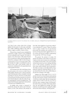
IN A WIDE, UNCONSTRICTED REGION, A RIVER FLOWS SLOWLY. HOWEVER, IF ITS FLOW IS NARROWED BY CANYON
WALLS
, AS WITH WYOMING’S BIGHORN RIVER, THEN IT SPEEDS UP DRAMATICALLY. (Photograph by Kevin R. Morris/Corbis.
Reproduced by permission.)
set_vol2_sec3 9/13/01 12:36 PM Page 96
Fluid
Mechanics
least as great as those of Pascal’s principle. This
was Archimedes’s principle, which explains the
buoyancy of an object immersed in fluid.
According to Archimedes’s principle, the buoyant
force exerted on the object is equal to the weight
of the fluid it displaces.
Buoyancy explains both how a ship floats on
water, and how a balloon floats in the air. The
pressures of water at the bottom of the ocean,
and of air at the surface of Earth, are both exam-
ples of hydrostatic pressure—the pressure that
exists at any place in a body of fluid due to the
weight of the fluid above. In the case of air pres-
sure, air is pulled downward by the force of
Earth’s gravitation, and air along the planet’s sur-
face has greater pressure due to the weight of the
air above it. At great heights above Earth’s sur-
face, however, the gravitational force is dimin-
ished, and thus the air pressure is much smaller.
Water, too, is pulled downward by gravity,
and as with air, the fluid at the bottom of the
ocean has much greater pressure due to the
weight of the fluid above it. Of course, water is
much heavier than air, and therefore, water at
even a moderate depth in the ocean has enor-
mous pressure. This pressure, in turn, creates a
buoyant force that pushes upward.
If an object immersed in fluid—a balloon in
the air, or a ship on the ocean—weighs less that
the fluid it displaces, it will float. If it weighs
more, it will sink or fall. The balloon itself may be
“heavier than air,” but it is not as heavy as the air
it has displaced. Similarly, an aircraft carrier con-
tains a vast weight in steel and other material, yet
it floats, because its weight is not as great as that
of the displaced water.
BERNOULLI’S PRINCIPLE. Ar-
chimedes and Pascal contributed greatly to what
became known as fluid statics, but the father of
fluid mechanics, as a larger realm of study, was
the Swiss mathematician and physicist Daniel
Bernoulli (1700-1782). While conducting exper-
iments with liquids, Bernoulli observed that
when the diameter of a pipe is reduced, the water
flows faster. This suggested to him that some
force must be acting upon the water, a force that
he reasoned must arise from differences in pres-
sure.
Specifically, the slower-moving fluid in the
wider area of pipe had a greater pressure than the
portion of the fluid moving through the narrow-
er part of the pipe. As a result, he concluded that
97
SCIENCE OF EVERYDAY THINGS
VOLUME 2: REAL-LIFE PHYSICS
pressure and velocity are inversely related—in
other words, as one increases, the other decreas-
es. Hence, he formulated Bernoulli’s principle,
which states that for all changes in movement,
the sum of static and dynamic pressure in a fluid
remains the same.
A fluid at rest exerts pressure—what
Bernoulli called “static pressure”—on its con-
tainer. As the fluid begins to move, however, a
portion of the static pressure—proportional to
the speed of the fluid—is converted to what
Bernoulli called dynamic pressure, or the pres-
sure of movement. In a cylindrical pipe, static
pressure is exerted perpendicular to the surface
of the container, whereas dynamic pressure is
parallel to it.
According to Bernoulli’s principle, the
greater the velocity of flow in a fluid, the greater
the dynamic pressure and the less the static pres-
sure. In other words, slower-moving fluid exerts
greater pressure than faster-moving fluid. The
discovery of this principle ultimately made pos-
sible the development of the airplane.
REAL-LIFE
APPLICATIONS
Bernoulli’s Principle in
Action
As fluid moves from a wider pipe to a narrower
one, the volume of the fluid that moves a given
distance in a given time period does not change.
But since the width of the narrower pipe is small-
er, the fluid must move faster (that is, with
greater dynamic pressure) in order to move the
same amount of fluid the same distance in the
same amount of time. Observe the behavior of a
river: in a wide, unconstricted region, it flows
slowly, but if its flow is narrowed by canyon walls,
it speeds up dramatically.
Bernoulli’s principle ultimately became the
basis for the airfoil, the design of an airplane’s
wing when seen from the end. An airfoil is
shaped like an asymmetrical teardrop laid on its
side, with the “fat” end toward the airflow. As air
hits the front of the airfoil, the airstream divides,
part of it passing over the wing and part passing
under. The upper surface of the airfoil is curved,
however, whereas the lower surface is much
straighter.
set_vol2_sec3 9/13/01 12:36 PM Page 97
Fluid
Mechanics
As a result, the air flowing over the top has a
greater distance to cover than the air flowing
under the wing. Since fluids have a tendency to
compensate for all objects with which they come
into contact, the air at the top will flow faster to
meet the other portion of the airstream, the air
flowing past the bottom of the wing, when both
reach the rear end of the airfoil. Faster airflow, as
demonstrated by Bernoulli, indicates lower pres-
sure, meaning that the pressure on the bottom of
the wing keeps the airplane aloft.
CREATING A DRAFT. Among the
most famous applications of Bernoulli’s princi-
ple is its use in aerodynamics, and this is dis-
cussed in the context of aerodynamics itself else-
where in this book. Likewise, a number of other
applications of Bernoulli’s principle are exam-
ined in an essay devoted to that topic. Bernoulli’s
principle, for instance, explains why a shower
curtain tends to billow inward when the water is
turned on; in addition, it shows why an open
window and door together create a draft.
Suppose one is in a hotel room where the
heat is on too high, and there is no way to adjust
the thermostat. Outside, however, the air is cold,
and thus, by opening a window, one can presum-
ably cool down the room. But if one opens the
window without opening the front door of the
room, there will be little temperature change.
The only way to cool off will be by standing next
to the window: elsewhere in the room, the air will
be every bit as stuffy as before. But if the door
leading to the hotel hallway is opened, a nice cool
breeze will blow through the room. Why?
With the door closed, the room constitutes
an area of relatively high pressure compared to
the pressure of the air outside the window.
Because air is a fluid, it will tend to flow into the
room, but once the pressure inside reaches a cer-
tain point, it will prevent additional air from
entering. The tendency of fluids is to move from
high-pressure to low-pressure areas, not the
other way around. As soon as the door is opened,
the relatively high-pressure air of the room flows
into the relatively low-pressure area of the hall-
way. As a result, the air pressure in the room is
reduced, and the air from outside can now enter.
Soon a wind will begin to blow through the
room.
A WIND TUNNEL. The above sce-
nario of wind flowing through a room describes
a rudimentary wind tunnel. A wind tunnel is a
chamber built for the purpose of examining the
characteristics of airflow in contact with solid
objects, such as aircraft and automobiles. The
wind tunnel represents a safe and judicious use
of the properties of fluid mechanics. Its purpose
is to test the interaction of airflow and solids in
relative motion: in other words, either the air-
craft has to be moving against the airflow, as it
does in flight, or the airflow can be moving
against a stationary aircraft. The first of these
choices, of course, poses a number of dangers; on
the other hand, there is little danger in exposing
a stationary craft to winds at speeds simulating
that of the aircraft in flight.
The first wind tunnel was built in England in
1871, and years later, aircraft pioneers Orville
(1871-1948) and Wilbur (1867-1912) Wright
used a wind tunnel to improve their planes. By
the late 1930s, the U.S. National Advisory Com-
mittee for Aeronautics (NACA) was building
wind tunnels capable of creating speeds equal to
300 MPH (480 km/h); but wind tunnels built
after World War II made these look primitive.
With the development of jet-powered flight, it
became necessary to build wind tunnels capable
of simulating winds at the speed of sound—760
MPH (340 m/s). By the 1950s, wind tunnels were
being used to simulate hypersonic speeds—that
is, speeds of Mach 5 (five times the speed of
sound) and above. Researchers today use helium
to create wind blasts at speeds up to Mach 50.
Fluid Mechanics for Per-
forming Work
HYDRAULIC PRESSES. Though
applications of Bernoulli’s principle are among
the most dramatic examples of fluid mechanics
in operation, the everyday world is filled with
instances of other ideas at work. Pascal’s princi-
ple, for instance, can be seen in the operation of
any number of machines that represent varia-
tions on the idea of a hydraulic press. Among
these is the hydraulic jack used to raise a car off
the floor of an auto mechanic’s shop.
Beneath the floor of the shop is a chamber
containing a quantity of fluid, and at either end
of the chamber are two large cylinders side by
side. Each cylinder holds a piston, and valves
control flow between the two cylinders through
the channel of fluid that connects them. In accor-
dance with Pascal’s principle, when one applies
force by pressing down the piston in one cylinder
98
SCIENCE OF EVERYDAY THINGS
VOLUME 2: REAL-LIFE PHYSICS
set_vol2_sec3 9/13/01 12:36 PM Page 98
Fluid
Mechanics
(the input cylinder), this yields a uniform pres-
sure that causes output in the second cylinder,
pushing up a piston that raises the car.
Another example of a hydraulic press is the
hydraulic ram, which can be found in machines
ranging from bulldozers to the hydraulic lifts
used by firefighters and utility workers to reach
heights. In a hydraulic ram, however, the charac-
teristics of the input and output cylinders are
reversed from those of a car jack. For the car jack,
the input cylinder is long and narrow, while the
output cylinder is wide and short. This is because
the purpose of a car jack is to raise a heavy object
through a relatively short vertical range of move-
ment—just high enough so that the mechanic
can stand comfortably underneath the car.
In the hydraulic ram, the input or master
cylinder is short and squat, while the output or
slave cylinder is tall and narrow. This is because
the hydraulic ram, in contrast to the car jack, car-
ries a much lighter cargo (usually just one per-
son) through a much greater vertical range—for
instance, to the top of a tree or building.
PUMPS. A pump is a device made for
moving fluid, and it does so by utilizing a pres-
sure difference, causing the fluid to move from
an area of higher pressure to one of lower pres-
sure. Its operation is based on aspects both of
Pascal’s and Bernoulli’s principles—though, of
course, humans were using pumps thousands of
years before either man was born.
A siphon hose used to draw gas from a car’s
fuel tank is a very simple pump. Sucking on one
end of the hose creates an area of low pressure
compared to the relatively high-pressure area of
the gas tank. Eventually, the gasoline will come
out of the low-pressure end of the hose.
The piston pump, slightly more complex,
consists of a vertical cylinder along which a pis-
ton rises and falls. Near the bottom of the cylin-
der are two valves, an inlet valve through which
fluid flows into the cylinder, and an outlet valve
through which fluid flows out. As the piston
moves upward, the inlet valve opens and allows
fluid to enter the cylinder. On the downstroke,
the inlet valve closes while the outlet valve opens,
and the pressure provided by the piston forces
the fluid through the outlet valve.
One of the most obvious applications of the
piston pump is in the engine of an automobile.
In this case, of course, the fluid being pumped is
gasoline, which pushes the pistons up and down
by providing a series of controlled explosions
created by the spark plug’s ignition of the gas. In
another variety of piston pump—the kind used
to inflate a basketball or a bicycle tire—air is the
fluid being pumped. Then there is a pump for
water. Pumps for drawing usable water from the
ground are undoubtedly the oldest known vari-
ety, but there are also pumps designed to remove
water from areas where it is undesirable; for
example, a bilge pump, for removing water from
a boat, or the sump pump used to pump flood
water out of a basement.
FLUID POWER. For several thousand
years, humans have used fluids—in particular
water—to power a number of devices. One of the
great engineering achievements of ancient times
was the development of the waterwheel, which
included a series of buckets along the rim that
made it possible to raise water from the river
below and disperse it to other points. By about 70
B.C., Roman engineers recognized that they could
use the power of water itself to turn wheels and
grind grain. Thus, the waterwheel became one of
the first mechanisms in which an inanimate
99
SCIENCE OF EVERYDAY THINGS
VOLUME 2: REAL-LIFE PHYSICS
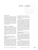
PUMPS FOR DRAWING USABLE WATER FROM THE
GROUND ARE UNDOUBTEDLY THE OLDEST PUMPS
KNOWN
. (Photograph by Richard Cummins/Corbis. Reproduced by
permission.)
set_vol2_sec3 9/13/01 12:36 PM Page 99
Fluid
Mechanics
100
SCIENCE OF EVERYDAY THINGS
VOLUME 2: REAL-LIFE PHYSICS
source (as opposed to the effort of humans or
animals) created power.
The water clock, too, was another ingenious
use of water developed by the ancients. It did not
use water for power; rather, it relied on gravity—
a concept only dimly understood by ancient peo-
ples—to move water from one chamber of the
clock to another, thus, marking a specific interval
of time. The earliest clocks were sundials, which
were effective for measuring time, provided the
Sun was shining, but which were less useful for
measuring periods shorter than an hour. Hence,
AERODYNAMICS: An area of fluid
dynamics devoted to studying the proper-
ties and characteristics of airflow.
ARCHIMEDES’S PRINCIPLE: A rule
of physics stating that the buoyant force of
an object immersed in fluid is equal to the
weight of the fluid displaced by the object.
It is named after the Greek mathematician,
physicist, and inventor, Archimedes (c.
287-212
B.C.), who first identified it.
BERNOULLI’S PRINCIPLE: A prop-
osition, credited to Swiss mathematician
and physicist Daniel Bernoulli (1700-
1782), which maintains that slower-mov-
ing fluid exerts greater pressure than faster-
moving fluid.
BUOYANCY: The tendency of an object
immersed in a fluid to float. This can be
explained by Archimedes’s principle.
COMPRESSION: To reduce in size or
volume by applying pressure.
FLUID: Any substance, whether gas or
liquid, that conforms to the shape of its
container.
FLUID DYNAMICS: An area of fluid
mechanics devoted to studying of the
behavior of moving, or flowing, fluids.
Fluid dynamics is further divided into
hydrodynamics and aerodynamics.
FLUID MECHANICS: The study of
the behavior of gases and liquids at rest
and in motion. The major divisions of
fluid mechanics are fluid statics and fluid
dynamics.
FLUID STATICS: An area of fluid
mechanics devoted to studying the behav-
ior of stationary fluids.
HYDRODYNAMICS: An area of fluid
dynamics devoted to studying the proper-
ties and characteristics of water flow.
HYDROSTATIC PRESSURE: The
pressure that exists at any place in a body of
fluid due to the weight of the fluid above.
PASCAL’S PRINCIPLE: A statement,
formulated by French mathematician and
physicist Blaise Pascal (1623-1662), which
holds that the external pressure applied on
a fluid is transmitted uniformly through-
out the entire body of that fluid.
PRESSURE: The ratio of force to sur-
face area, when force is applied in a direc-
tion perpendicular to that surface.
TURBINE: A machine that converts the
kinetic energy (the energy of movement)
in fluids to useable mechanical energy by
passing the stream of fluid through a series
of fixed and moving fans or blades.
WIND TUNNEL: A chamber built for
the purpose of examining the characteris-
tics of airflow in relative motion against
solid objects such as aircraft and auto-
mobiles.
KEY TERMS
set_vol2_sec3 9/13/01 12:36 PM Page 100
Fluid
Mechanics
the development of the hourglass, which used
sand, a solid that in larger quantities exhibits the
behavior of a fluid. Then, in about 270
B.C., Cte-
sibius of Alexandria (fl. c. 270-250
B.C.) used
gearwheel technology to devise a constant-flow
water clock called a “clepsydra.” Use of water
clocks prevailed for more than a thousand years,
until the advent of the first mechanical clocks.
During the medieval period, fluids provided
power to windmills and water mills, and at the
dawn of the Industrial Age, engineers began
applying fluid principles to a number of sophis-
ticated machines. Among these was the turbine, a
machine that converts the kinetic energy (the
energy of movement) in fluids to useable
mechanical energy by passing the stream of fluid
through a series of fixed and moving fans or
blades. A common house fan is an example of a
turbine in reverse: the fan adds energy to the
passing fluid (air), whereas a turbine extracts
energy from fluids such as air and water.
The turbine was developed in the mid-eigh-
teenth century, and later it was applied to the
extraction of power from hydroelectric dams, the
first of which was constructed in 1894. Today,
hydroelectric dams provide electric power to
millions of homes around the world. Among the
most dramatic examples of fluid mechanics in
action, hydroelectric dams are vast in size and
equally impressive in the power they can generate
using a completely renewable resource: water.
A hydroelectric dam forms a huge steel-and-
concrete curtain that holds back millions of tons
of water from a river or other body. The water
nearest the top—the “head” of the dam—has
enormous potential energy, or the energy that an
object possesses by virtue of its position. Hydro-
electric power is created by allowing controlled
streams of this water to flow downward, gather-
ing kinetic energy that is then transferred to
powering turbines, which in turn generate elec-
tric power.
WHERE TO LEARN MORE
Aerodynamics for Students (Web site).
< (April
8, 2001).
Beiser, Arthur. Physics, 5th ed. Reading, MA: Addison-
Wesley, 1991.
Chahrour, Janet. Flash! Bang! Pop! Fizz!: Exciting Science
for Curious Minds. Illustrated by Ann Humphrey
Williams. Hauppauge, N.Y.: Barron’s, 2000.
“Educational Fluid Mechanics Sites.” Virginia Institute of
Technology (Web site). < />ids/links/edulinks.htm> (April 8, 2001).
Fleisher, Paul. Liquids and Gases: Principles of Fluid
Mechanics. Minneapolis, MN: Lerner Publications,
2002.
Institute of Fluid Mechanics (Web site).
<> (April 8, 2001).
K8AIT Principles of Aeronautics Advanced Text (web site).
< />(February 19, 2001).
Macaulay, David. The New Way Things Work. Boston:
Houghton Mifflin, 1998.
Sobey, Edwin J. C. Wacky Water Fun with Science: Science
You Can Float, Sink, Squirt, and Sail. Illustrated by
Bill Burg. New York: McGraw-Hill, 2000.
Wood, Robert W. Mechanics Fundamentals. Illustrated by
Bill Wright. Philadelphia: Chelsea House, 1997.
101
SCIENCE OF EVERYDAY THINGS
VOLUME 2: REAL-LIFE PHYSICS
set_vol2_sec3 9/13/01 12:36 PM Page 101
102
SCIENCE OF EVERYDAY THINGS
VOLUME 2: REAL-LIFE PHYSICS
AERODYNAMICS
Aerodynamics
CONCEPT
Though the term “aerodynamics” is most com-
monly associated with airplanes and the overall
science of flight, in fact, its application is much
broader. Simply put, aerodynamics is the study of
airflow and its principles, and applied aerody-
namics is the science of improving manmade
objects such as airplanes and automobiles in light
of those principles. Aside from the obvious appli-
cation to these heavy forms of transportation,
aerodynamic concepts are also reflected in the
simplest of manmade flying objects—and in the
natural model for all studies of flight, a bird’s
wings.
HOW IT WORKS
All physical objects on Earth are subject to grav-
ity, but gravity is not the only force that tends to
keep them pressed to the ground. The air itself,
though it is invisible, operates in such a way as to
prevent lift, much as a stone dropped into the
water will eventually fall to the bottom. In fact,
air behaves much like water, though the down-
ward force is not as great due to the fact that air’s
pressure is much less than that of water. Yet both
are media through which bodies travel, and air
and water have much more in common with one
another than either does with a vacuum.
Liquids such as water and gasses such as air
are both subject to the principles of fluid dynam-
ics, a set of laws that govern the motion of liquids
and vapors when they come in contact with solid
surfaces. In fact, there are few significant differ-
ences—for the purposes of the present discus-
sion—between water and air with regard to their
behavior in contact with solid surfaces.
When a person gets into a bathtub, the water
level rises uniformly in response to the fact that a
solid object is taking up space. Similarly, air cur-
rents blow over the wings of a flying aircraft in
such a way that they meet again more or less
simultaneously at the trailing edge of the wing.
In both cases, the medium adjusts for the intru-
sion of a solid object. Hence within the parame-
ters of fluid dynamics, scientists typically use the
term “fluid” uniformly, even when describing the
movement of air.
The study of fluid dynamics in general, and
of air flow in particular, brings with it an entire
vocabulary. One of the first concepts of impor-
tance is viscosity, the internal friction in a fluid
that makes it resistant to flow and resistant to
objects flowing through it. As one might suspect,
viscosity is a far greater factor with water than
with air, the viscosity of which is less than two
percent that of water. Nonetheless, near a solid
surface—for example, the wing of an airplane—
viscosity becomes a factor because air tends to
stick to that surface.
Also significant are the related aspects of
density and compressibility. At speeds below 220
MPH (354 km/h), the compressibility of air is
not a significant factor in aerodynamic design.
However, as air flow approaches the speed of
sound—660 MPH (1,622 km/h)—compressibil-
ity becomes a significant factor. Likewise temper-
ature increases greatly when airflow is superson-
ic, or faster than the speed of sound.
All objects in the air are subject to two types
of airflow, laminar and turbulent. Laminar flow
is smooth and regular, always moving at the same
speed and in the same direction. This type of air-
flow is also known as streamlined flow, and
under these conditions every particle of fluid that
set_vol2_sec3 9/13/01 12:36 PM Page 102
Aero-
dynamics
passes a particular point follows a path identical
to all particles that passed that point earlier. This
may be illustrated by imagining a stream flowing
around a twig.
By contrast, in turbulent flow the air is sub-
ject to continual changes in speed and direc-
tion—as for instance when a stream flows over
shoals of rocks. Whereas the mathematical model
of laminar airflow is rather straightforward, con-
ditions are much more complex in turbulent
flow, which typically occurs in the presence
either of obstacles or of high speeds.
Absent the presence of viscosity, and thus in
conditions of perfect laminar flow, an object
behaves according to Bernoulli’s principle, some-
times known as Bernoulli’s equation. Named after
the Swiss mathematician and physicist Daniel
Bernoulli (1700-1782), this proposition goes to
the heart of that which makes an airplane fly.
While conducting experiments concerning
the conservation of energy in liquids, Bernoulli
observed that when the diameter of a pipe is
reduced, the water flows faster. This suggested to
him that some force must be acting upon the
water, a force that he reasoned must arise from
differences in pressure. Specifically, the slower-
moving fluid had a greater pressure than the por-
tion of the fluid moving through the narrower
part of the pipe. As a result, he concluded that
pressure and velocity are inversely related.
Bernoulli’s principle states that for all
changes in movement, the sum of static and
dynamic pressure in a fluid remain the same. A
fluid at rest exerts static pressure, which is the
same as what people commonly mean when they
say “pressure,” as in “water pressure.” As the fluid
begins to move, however, a portion of the static
pressure—proportional to the speed of the
fluid—is converted to what scientists call dynam-
ic pressure, or the pressure of movement. The
greater the speed, the greater the dynamic pres-
sure and the less the static pressure. Bernoulli’s
findings would prove crucial to the design of air-
craft in the twentieth century, as engineers
learned how to use currents of faster and slower
air for keeping an airplane aloft.
Very close to the surface of an object experi-
encing airflow, however, the presence of viscosity
plays havoc with the neat proportions of the
Bernoulli’s principle. Here the air sticks to the
object’s surface, slowing the flow of nearby air
and creating a “boundary layer” of slow-moving
103
SCIENCE OF EVERYDAY THINGS
VOLUME 2: REAL-LIFE PHYSICS
air. At the beginning of the flow—for instance, at
the leading edge of an airplane’s wing—this
boundary layer describes a laminar flow; but the
width of the layer increases as the air moves
along the surface, and at some point it becomes
turbulent.
These and a number of other factors con-
tribute to the coefficients of drag and lift. Simply
put, drag is the force that opposes the forward
motion of an object in airflow, whereas lift is a
force perpendicular to the direction of the wind,
which keeps the object aloft. Clearly these con-
cepts can be readily applied to the operation of
an airplane, but they also apply in the case of an
automobile, as will be shown later.
REAL-LIFE
APPLICATIONS
How a Bird Flies—and Why a
Human Being Cannot
Birds are exquisitely designed (or adapted) for
flight, and not simply because of the obvious fact
A TYPICAL PAPER AIRPLANE HAS LOW ASPECT RATIO
WINGS
, A TERM THAT REFERS TO THE SIZE OF THE
WINGSPAN COMPARED TO THE CHORD
. IN SUBSONIC
FLIGHT, HIGHER ASPECT RATIOS ARE USUALLY PRE-
FERRED. (Photograph by Bruce Burkhardt/Corbis. Reproduced by per-
mission.)
set_vol2_sec3 9/13/01 12:36 PM Page 103
BIRDS LIKE THESE FAIRY TERNS ARE SUPREME EXAMPLES OF AERODYNAMIC PRINCIPLES, FROM THEIR LOW BODY
WEIGHT AND LARGE STERNUM AND PECTORALIS MUSCLES TO THEIR LIGHTWEIGHT FEATHERS
. (Corbis. Reproduced by per-
mission.)
Aero-
dynamics
When a bird beats its wings, its downstrokes
propel it, and as it rises above the ground, the
force of aerodynamic lift helps push its wings
upward in preparation for the next downstroke.
However, to reduce aerodynamic drag during the
upstroke, the bird folds its wings, thus decreasing
its wingspan. Another trick that birds execute
instinctively is the moving of their wings forward
and backward in order to provide balance. They
also “know” how to flap their wings in a direction
almost parallel to the ground when they need to
fly slowly or hover.
Witnessing the astonishing aerodynamic
feats of birds, humans sought the elusive goal of
flight from the earliest of times. This was sym-
bolized by the Greek myth of Icarus and
Daedalus, who escaped from a prison in Crete by
constructing a set of bird-like wings and flying
away. In the world of physical reality, however,
the goal would turn out to be unattainable as
long as humans attempted to achieve flight by
imitating birds.
As noted earlier, a bird’s physiology is quite
different from that of a human being. There is
simply no way that a human can fly by flapping
his arms—nor will there ever be a man strong
enough to do so, no matter how apparently well-
104
SCIENCE OF EVERYDAY THINGS
VOLUME 2: REAL-LIFE PHYSICS
that they have wings. Thanks to light, hollow
bones, their body weight is relatively low, giving
them the advantage in overcoming gravity and
remaining aloft. Furthermore, a bird’s sternum
or breast bone, as well as its pectoralis muscles
(those around the chest) are enormous in pro-
portion to its body size, thus helping it to achieve
the thrust necessary for flight. And finally, the
bird’s lightweight feathers help to provide opti-
mal lift and minimal drag.
A bird’s wing is curved along the top, a cru-
cial aspect of its construction. As air passes over
the leading edge of the wing, it divides, and
because of the curve, the air on top must travel a
greater distance before meeting the air that
flowed across the bottom. The tendency of air-
flow, as noted earlier, is to correct for the presence
of solid objects. Therefore, in the absence of out-
side factors such as viscosity, the air on top “tries”
to travel over the wing in the same amount of
time that it takes the air below to travel under the
wing. As shown by Bernoulli, the fast-moving air
above the wing exerts less pressure than the slow-
moving air below it; hence there is a difference in
pressure between the air below and the air above,
and this keeps the wing aloft.
set_vol2_sec3 9/13/01 12:36 PM Page 104
Aero-
dynamics
105
SCIENCE OF EVERYDAY THINGS
VOLUME 2: REAL-LIFE PHYSICS
designed his mechanical wings are. Indeed, to be
capable of flying like a bird, a man would have to
have a chest so enormous in proportion to his
body that he would be hideous in appearance.
Not realizing this, humans for centuries
attempted to fly like birds—with disastrous
results. An English monk named Eilmer (b. 980)
attempted to fly off the tower of Malmesbury
Abbey with a set of wings attached to his arms
and feet. Apparently Eilmer panicked after glid-
ing some 600 ft (about 200 m) and suddenly
plummeted to earth, breaking both of his legs. At
least he lived; more tragic was the case of Abul
Qasim Ibn Firnas (d. 873), an inventor from Cor-
doba in Arab Spain who devised and demon-
strated a glider. Much of Cordoba’s population
came out to see him demonstrate his flying
machine, but after covering just a short distance,
the craft fell to earth. Severely wounded, Ibn Fir-
nas died shortly afterward.
The first real progress in the development of
flying machines came when designers stopped
trying to imitate birds and instead used the prin-
ciple of buoyancy. Hence in 1783, the French
brothers Jacques-Etienne and Joseph-Michel
Montgolfier constructed the first practical bal-
loon.
Balloons and their twentieth-century
descendant, the dirigible, had a number of obvi-
ous drawbacks, however. Without a motor, a bal-
loon could not be guided, and even with a motor,
dirigibles proved highly dangerous. At that stage,
most dirigibles used hydrogen, a gas that is cheap
and plentiful, but extremely flammable. After the
Hindenburg exploded in 1937, the age of passen-
ger travel aboard airships was over.
However, the German military continued to
use dirigibles for observation purposes, as did the
United States forces in World War II. Today air-
ships, the most famous example being the
Goodyear Blimp, are used not only for observa-
tion but for advertising. Scientists working in
rain forests, for instance, use dirigibles to glide
above the forest canopy; as for the Goodyear
Blimp, it provides television networks with “eye
in the sky” views of large sporting events.
The first man to make a serious attempt at
creating a heavier-than-air flying machine (as
opposed to a balloon, which uses gases that are
lighter than air) was Sir George Cayley (1773-
1857), who in 1853 constructed a glider. It is
interesting to note that in creating this, the fore-
runner of the modern airplane, Cayley went back
to an old model: the bird. After studying the
physics of birds’ flight for many years, he
equipped his glider with an extremely wide
wingspan, used the lightest possible materials in
its construction, and designed it with exception-
ally smooth surfaces to reduce drag.
The only thing that in principle differentiat-
ed Cayley’s craft from a modern airplane was its
lack of an engine. In those days, the only possible
source of power was a steam engine, which
would have added far too much weight to his air-
craft. However, the development of the internal-
combustion engine in the nineteenth century
overcame that obstacle, and in 1903 Orville and
Wilbur Wright achieved the dream of flight that
had intrigued and eluded human beings for cen-
turies.
Airplanes: Getting Aloft,
Staying Aloft, and Remaining
Stable
Once engineers and pilots took to the air, they
encountered a number of factors that affect
flight. In getting aloft and staying aloft, an air-
craft is subject to weight, lift, drag, and thrust.
As noted earlier, the design of an airplane
wing takes advantage of Bernoulli’s principle to
give it lift. Seen from the end, the wing has the
shape of a long teardrop lying on its side, with
the large end forward, in the direction of airflow,
and the narrow tip pointing toward the rear.
(Unlike a teardrop, however, an airplane’s wing is
asymmetrical, and the bottom side is flat.) This
cross-section is known as an airfoil, and the
greater curvature of its upper surface in compar-
ison to the lower side is referred to as the air-
plane’s camber. The front end of the airfoil is also
curved, and the chord line is an imaginary
straight line connecting the spot where the air
hits the front—known as the stagnation point—
to the rear, or trailing edge, of the wing.
Again in accordance with Bernoulli’s princi-
ple, the shape of the airflow facilitates the spread
of laminar flow around it. The slower-moving
currents beneath the airfoil exert greater pressure
than the faster currents above it, giving lift to the
aircraft.
Another parameter influencing the lift coef-
ficient (that is, the degree to which the aircraft
experiences lift) is the size of the wing: the longer
the wing, the greater the total force exerted
set_vol2_sec3 9/13/01 12:36 PM Page 105
Aero-
dynamics
beneath it, and the greater the ratio of this pres-
sure to that of the air above. The size of a mod-
ern aircraft’s wing is actually somewhat variable,
due to the presence of flaps at the trailing edge.
With regard to the flaps, however, it should
be noted that they have different properties at
different stages of flight: in takeoff, they provide
lift, but in stable flight they increase drag, and for
that reason the pilot retracts them. In preparing
for landing, as the aircraft slows and descends,
the extended flaps then provide stability and
assist in the decrease of speed.
Speed, too, encourages lift: the faster the
craft, the faster the air moves over the wing. The
pilot affects this by increasing or decreasing the
power of the engine, thus regulating the speed
with which the plane’s propellers turn. Another
highly significant component of lift is the airfoil’s
angle of attack—the orientation of the airfoil
with regard to the air flow, or the angle that the
chord line forms with the direction of the air
stream.
Up to a point, increasing the angle of attack
provides the aircraft with extra lift because it
moves the stagnation point from the leading
edge down along the lower surface; this increases
the low-pressure area of the upper surface. How-
ever, if the pilot increases the angle of attack too
much, this affects the boundary layer of slow-
moving air, causing the aircraft to go into a stall.
Together the engine provides the propellers
with power, and this gives the aircraft thrust, or
propulsive force. In fact, the propeller blades
constitute miniature wings, pivoted at the center
and powered by the engine to provide rotational
motion. As with the wings of the aircraft, the
blades have a convex forward surface and a nar-
row trailing edge. Also like the aircraft wings,
their angle of attack (or pitch) is adjusted at dif-
ferent points for differing effects. In stable flight,
the pilot increases the angle of attack for the pro-
peller blades sharply as against airflow, whereas
at takeoff and landing the pitch is dramatically
reduced. During landing, in fact, the pilot actual-
ly reverses the direction of the propeller blades,
turning them into a brake on the aircraft’s for-
ward motion—and producing that lurching sen-
sation that a passenger experiences as the aircraft
slows after touching down.
By this point there have been several exam-
ples regarding the use of the same technique
alternately to provide lift or—when slowing or
preparing to land—drag. This apparent inconsis-
tency results from the fact that the characteristics
of air flow change drastically from situation to
situation, and in fact, air never behaves as per-
fectly as it does in a textbook illustration of
Bernoulli’s principle.
Not only is the aircraft subject to air viscosi-
ty—the air’s own friction with itself—it also
experiences friction drag, which results from the
fact that no solid can move through a fluid with-
out experiencing a retarding force. An even
greater drag factor, accounting for one-third of
that which an aircraft experiences, is induced
drag. The latter results because air does not flow
in perfect laminar streams over the airfoil; rather,
it forms turbulent eddies and currents that act
against the forward movement of the plane.
In the air, an aircraft experiences forces that
tend to destabilize flight in each of three dimen-
sions. Pitch is the tendency to rotate forward or
backward; yaw, the tendency to rotate on a hori-
zontal plane; and roll, the tendency to rotate ver-
tically on the axis of its fuselage. Obviously, each
of these is a terrifying prospect, but fortunately,
pilots have a solution for each. To prevent pitch-
ing, they adjust the angle of attack of the hori-
zontal tail at the rear of the craft. The vertical rear
tail plays a part in preventing yawing, and to pre-
vent rolling, the pilot raises the tips of the main
wings so that the craft assumes a V-shape when
seen from the front or back.
The above factors of lift, drag, thrust, and
weight, as well as the three types of possible
destabilization, affect all forms of heavier-than-
air flying machines. But since the 1944 advent of
jet engines, which travel much faster than piston-
driven engines, planes have flown faster and
faster, and today some craft such as the Concorde
are capable of supersonic flight. In these situa-
tions, air compressibility becomes a significant
issue.
Sound is transmitted by the successive com-
pression and expansion of air. But when a plane
is traveling at above Mach 1.2—the Mach num-
ber indicates the speed of an aircraft in relation
to the speed of sound—there is a significant dis-
crepancy between the speed at which sound is
traveling away from the craft, and the speed at
which the craft is moving away from the sound.
Eventually the compressed sound waves build up,
resulting in a shock wave.
106
SCIENCE OF EVERYDAY THINGS
VOLUME 2: REAL-LIFE PHYSICS
set_vol2_sec3 9/13/01 12:36 PM Page 106
Aero-
dynamics
Down on the ground, the shock wave mani-
fests as a “sonic boom”; meanwhile, for the air-
craft, it can cause sudden changes in pressure,
density, and temperature, as well as an increase in
drag and a loss of stability. To counteract this
effect, designers of supersonic and hypersonic
(Mach 5 and above) aircraft are altering wing
design, using a much narrower airfoil and swept-
back wings.
One of the pioneers in this area is Richard
Whitcomb of the National Aeronautics and
Space Administration (NASA). Whitcomb has
designed a supercritical airfoil for a proposed
hypersonic plane, which would ascend into outer
space in the course of a two-hour flight—all the
time needed for it to travel from Washington,
D.C., to Tokyo, Japan. Before the craft can
become operational, however, researchers will
have to figure out ways to control temperatures
and keep the plane from bursting into flame as it
reenters the atmosphere.
Much of the research for improving the
aerodynamic qualities of such aircraft takes place
in wind tunnels. First developed in 1871, these
use powerful fans to create strong air currents,
and over the years the top speed in wind tunnels
has been increased to accommodate testing on
supersonic and hypersonic aircraft. Researchers
today use helium to create wind blasts at speeds
up to Mach 50.
Thrown and Flown: The Aero-
dynamics of Small Objects
Long before engineers began to dream of sending
planes into space for transoceanic flight—about
14,000 years ago, in fact—many of the features
that make an airplane fly were already present in
the boomerang. It might seem backward to move
from a hypersonic jet to a boomerang, but in
fact, it is easier to appreciate the aerodynamics of
small objects, including the kite and even the
paper airplane, once one comprehends the larger
picture.
There is a certain delicious irony in the fact
that the first manmade object to take flight was
constructed by people who never advanced
beyond the Stone Age until the nineteenth centu-
ry, when the Europeans arrived in Australia. As
the ethnobotanist Jared Diamond showed in his
groundbreaking work Guns, Germs, and Steel:
The Fates of Human Societies (1997), this was not
because the Aborigines of Australia were less
intelligent than Europeans. In fact, as Diamond
showed, an individual would actually have to be
smarter to figure out how to survive on the lim-
ited range of plants and animals available in Aus-
tralia prior to the introduction of Eurasian flora
and fauna. Hence the wonder of the boomerang,
one of the most ingenious inventions ever fash-
ioned by humans in a “primitive” state.
Thousands of years before Bernoulli, the
boomerang’s designers created an airfoil consis-
tent with Bernoulli’s principle. The air below
exerts more pressure than the air above, and this,
combined with the factors of gyroscopic stability
and gyroscopic precession, gives the boomerang
flight.
Gyroscopic stability can be illustrated by
spinning a top: the action of spinning itself keeps
the top stable. Gyroscopic precession is a much
more complex process: simply put, the leading
wing of the boomerang—the forward or upward
edge as it spins through the air—creates more lift
than the other wing. At this point it should be
noted that, contrary to the popular image, a
boomerang travels on a plane perpendicular to
that of the ground, not parallel. Hence any
thrower who knows what he or she is doing toss-
es the boomerang not with a side-arm throw, but
overhand.
And of course a boomerang does not just
sail through the air; a skilled thrower can make it
come back as if by magic. This is because the
force of the increased lift that it experiences in
flight, combined with gyroscopic precession,
turns it around. As noted earlier, in different sit-
uations the same force that creates lift can create
drag, and as the boomerang spins downward the
increasing drag slows it. Certainly it takes great
skill for a thrower to make a boomerang come
back, and for this reason, participants in
boomerang competitions often attach devices
such as flaps to increase drag on the return cycle.
Another very early example of an aerody-
namically sophisticated humanmade device—
though it is quite recent compared to the
boomerang—is the kite, which first appeared in
China in about 1000
B.C. The kite’s design bor-
rows from avian anatomy, particularly the bird’s
light, hollow bones. Hence a kite, in its simplest
form, consists of two crossed strips of very light
wood such as balsa, with a lightweight fabric
stretched over them.
107
SCIENCE OF EVERYDAY THINGS
VOLUME 2: REAL-LIFE PHYSICS
set_vol2_sec3 9/13/01 12:36 PM Page 107
Aero-
dynamics
Kites can come in a variety of shapes, though
for many years the well-known diamond shape
has been the most popular, in part because its
aerodynamic qualities make it easiest for the
novice kite-flyer to handle. Like birds and
boomerangs, kites can “fly” because of the physi-
cal laws embodied in Bernoulli’s principle: at the
best possible angle of attack, the kite experiences
a maximal ratio of pressure from the slower-
moving air below as against the faster-moving air
above.
For centuries, when the kite represented the
only way to put a humanmade object many hun-
dreds of feet into the air, scientists and engineers
used them for a variety of experiments. Of
course, the most famous example of this was
Benjamin Franklin’s 1752 experiment with elec-
tricity. More significant to the future of aerody-
namics were investigations made half a century
later by Cayley, who recognized that the kite,
rather than the balloon, was an appropriate
model for the type of heavier-than-air flight he
intended.
In later years, engineers built larger kites
capable of lifting men into the air, but the advent
of the airplane rendered kites obsolete for this
purpose. However, in the 1950s an American
engineer named Francis Rogallo invented the
flexible kite, which in turn spawned the delta
wing kite used by hang gliders. During the 1960s,
Domina Jolbert created the parafoil, an even
more efficient device, which took nonmecha-
nized human flight perhaps as far as it can go.
Akin to the kite, glider, and hang glider is
that creation of childhood fancy, the paper air-
plane. In its most basic form—and paper air-
plane enthusiasts are capable of fairly complex
designs—a paper airplane is little more than a set
of wings. There are a number or reasons for this,
not least the fact that in most cases, a person fly-
ing a paper airplane is not as concerned about
pitch, yaw, and roll as a pilot flying with several
hundred passengers on board would be.
However, when fashioning a paper airplane
it is possible to add a number of design features,
for instance by folding flaps upward at the tail.
These become the equivalent of the elevator, a
control surface along the horizontal edge of a real
aircraft’s tail, which the pilot rotates upward to
provide stability. But as noted by Ken Blackburn,
author of several books on paper airplanes, it is
not necessarily the case that an airplane must
have a tail; indeed, some of the most sophisticat-
ed craft in the sky today—including the fearsome
B-2 “Stealth” bomber—do not have tails.
A typical paper airplane has low aspect ratio
wings, a term that refers to the size of the
wingspan compared to the chord line. In subson-
ic flight, higher aspect ratios are usually pre-
ferred, and this is certainly the case with most
“real” gliders; hence their wings are longer, and
their chord lines shorter. But there are several
reasons why this is not the case with a paper air-
plane.
First of all, as Blackburn noted wryly on his
Web site, “Paper is a lousy building material.
There is a reason why real airplanes are not made
of paper.” He stated the other factors governing
paper airplanes’ low aspect ratio in similarly
whimsical terms. First, “Low aspect ratio wings
are easier to fold ”; second, “Paper airplane
gliding performance is not usually very impor-
tant ”; and third, “Low-aspect ratio wings look
faster, especially if they are swept back.”
The reason why low-aspect ratio wings look
faster, Blackburn suggested, is that people see
them on jet fighters and the Concorde, and
assume that a relatively narrow wing span with a
long chord line yields the fastest speeds. And
indeed they do—but only at supersonic speeds.
Below the speed of sound, high-aspect ratio
wings are best for preventing drag. Furthermore,
as Blackburn went on to note, low-aspect ratio
wings help the paper airplane to withstand the
relatively high launch speeds necessary to send
them into longer glides.
In fact, a paper airplane is not subject to any-
thing like the sort of design constraints affecting
a real craft. All real planes look somewhat similar,
because the established combinations, ratios, and
dimensions of wings, tails, and fuselage work
best. Certainly there is a difference in basic
appearance between subsonic and supersonic
aircraft—but again, all supersonic jets have more
or less the same low-aspect, swept wing. “With
paper airplanes,” Blackburn wrote, “it’s easy to
make airplanes that don’t look like real airplanes”
since “The mission of a paper airplane is [simply]
to provide a good time for the pilot.”
Aerodynamics on the Ground
The preceding discussions of aerodynamics in
action have concerned the behavior of objects off
the ground. But aerodynamics is also a factor in
108
SCIENCE OF EVERYDAY THINGS
VOLUME 2: REAL-LIFE PHYSICS
set_vol2_sec3 9/13/01 12:36 PM Page 108
Aero-
dynamics
109
SCIENCE OF EVERYDAY THINGS
VOLUME 2: REAL-LIFE PHYSICS
wheeled transport on Earth’s surface, whether by
bicycle, automobile, or some other variation.
On a bicycle, the rider accounts for 65-80%
of the drag, and therefore his or her position with
regard to airflow is highly important. Thus, from
as early as the 1890s, designers of racing bikes
have favored drop handlebars, as well as a seat
and frame that allow a crouched position. Since
the 1980s, bicycle designers have worked to elim-
inate all possible extra lines and barriers to air-
flow, including the crossbar and chainstays.
A typical bicycle’s wheel contains 32 or 36
cylindrical spokes, and these can affect aerody-
namics adversely. As the wheel rotates, the air-
flow behind the spoke separates, creating turbu-
lence and hence drag. For this reason, some of
the most advanced bicycles today use either aero-
dynamic rims, which reduce the length of the
spokes, three-spoke aerodynamic wheels, or even
solid wheels.
The rider’s gear can also serve to impede or
enhance his velocity, and thus modern racing
helmets have a streamlined shape—rather like
that of an airfoil. The best riders, such as those
who compete in the Olympics or the Tour de
France, have bikes custom-designed to fit their
own body shape.
One interesting aspect of aerodynamics
where it concerns bicycle racing is the phenome-
non of “drafting.” Riders at the front of a pack,
like riders pedaling alone, consume 30-40%
more energy than do riders in the middle of a
pack. The latter are benefiting from the efforts of
bicyclists in front of them, who put up most
of the wind resistance. The same is true for
bicyclists who ride behind automobiles or
motorcycles.
The use of machine-powered pace vehicles
to help in achieving extraordinary speeds is far
from new. Drafting off of a railroad car with spe-
cially designed aerodynamic shields, a rider in
1896 was able to exceed 60 MPH (96 km/h), a
then unheard-of speed. Today the record is just
under 167 MPH (267 km/h). Clearly one must be
a highly skilled, powerful rider to approach any-
thing like this speed; but design factors also come
into play, and not just in the case of the pace
vehicle. Just as supersonic jets are quite different
from ordinary planes, super high-speed bicycles
are not like the average bike; they are designed in
such a way that they must be moving faster than
60 MPH before the rider can even pedal.
With regard to automobiles, as noted earlier,
aerodynamics has a strong impact on body
design. For this reason, cars over the years have
become steadily more streamlined and aerody-
namic in appearance, a factor that designers bal-
ance with aesthetic appeal. Today’s Chrysler PT
Cruiser, which debuted in 2000, may share out-
ward features with 1930s and 1940s cars, but the
PT Cruiser’s design is much more sound aerody-
namically—not least because a modern vehicle
can travel much, much faster than the cars driv-
en by previous generations.
Nowhere does the connection between aero-
dynamics and automobiles become more crucial
than in the sport of auto racing. For race-car
drivers, drag is always a factor to be avoided and
counteracted by means ranging from drafting to
altering the body design to reduce the airflow
under the vehicle. However, as strange as it may
seem, a car—like an airplane—is also subject to
lift.
It was noted earlier that in some cases lift
can be undesirable in an airplane (for instance,
when trying to land), but it is virtually always
undesirable in an automobile. The greater the
speed, the greater the lift force, which increases
A PROFESSIONAL BICYCLE RACER’S STREAMLINED HEL-
MET AND CROUCHED POSITION HELP TO IMPROVE AIR
-
FLOW, THUS INCREASING SPEED. (Photograph by Ronnen
Eshel/Corbis. Reproduced by permission.)
set_vol2_sec3 9/13/01 12:36 PM Page 109
Aero-
dynamics
110
SCIENCE OF EVERYDAY THINGS
VOLUME 2: REAL-LIFE PHYSICS
the threat of instability. For this reason, builders
of race cars design their vehicles for negative lift:
hence a typical family car has a lift coefficient of
about 0.03, whereas a race car is likely to have a
coefficient of -3.00.
Among the design features most often used
to reduce drag while achieving negative lift is a
rear-deck spoiler. The latter has an airfoil shape,
but its purpose is different: to raise the rear stag-
nation point and direct air flow so that it does
not wrap around the vehicle’s rear end. Instead,
the spoiler creates a downward force to stabilize
the rear, and it may help to decrease drag by
reducing the separation of airflow (and hence the
creation of turbulence) at the rear window.
Similar in concept to a spoiler, though some-
what different in purpose, is the aerodynamically
curved shield that sits atop the cab of most mod-
ern eighteen-wheel transport trucks. The pur-
pose of the shield becomes apparent when the
AERODYNAMICS: The study of air
flow and its principles. Applied aerody-
namics is the science of improving man-
made objects in light of those principles.
AIRFOIL: The design of an airplane’s
wing when seen from the end, a shape
intended to maximize the aircraft’s
response to airflow.
ANGLE OF ATTACK: The orientation of
the airfoil with regard to the airflow, or the
angle that the chord line forms with the
direction of the air stream.
BERNOULLI’S PRINCIPLE: A proposi-
tion, credited to Swiss mathematician and
physicist Daniel Bernoulli (1700-1782),
which maintains that slower-moving fluid
exerts greater pressure than faster-moving
fluid.
CAMBER: The enhanced curvature on the
upper surface of an airfoil.
CHORD LINE: The distance, along an
imaginary straight line, from the stagna-
tion point of an airfoil to the rear, or trail-
ing edge.
DRAG: The force that opposes the forward
motion of an object in airflow.
LAMINAR: A term describing a stream-
lined flow, in which all particles move at
the same speed and in the same direction.
Its opposite is turbulent flow.
LIFT: An aerodynamic force perpendicu-
lar to the direction of the wind. For an air-
craft, lift is the force that raises it off the
ground and keeps it aloft.
PITCH: The tendency of an aircraft in
flight to rotate forward or backward; see
also yaw and roll.
ROLL: The tendency of an aircraft in
flight to rotate vertically on the axis of its
fuselage; see also pitch and yaw.
STAGNATION POINT: The spot where
airflow hits the leading edge of an airfoil.
SUPERSONIC: Faster than Mach 1, or
the speed of sound—660 MPH (1,622
km/h). Speeds above Mach 5 are referred to
as hypersonic.
TURBULENT: A term describing a highly
irregular form of flow, in which a fluid is
subject to continual changes in speed and
direction. Its opposite is laminar flow.
VISCOSITY: The internal friction in a
fluid that makes it resistant to flow.
YAW: The tendency of an aircraft in flight
to rotate on a horizontal plane; see also
Pitch and Roll.
KEY TERMS
set_vol2_sec3 9/13/01 12:36 PM Page 110
Aero-
dynamics
truck is moving at high speeds: wind resistance
becomes strong, and if the wind were to hit the
truck’s trailer head-on, it would be as though the
air were pounding a brick wall. Instead, the shield
scoops air upward, toward the rear of the truck.
At the rear may be another panel, patented by
two young engineers in 1994, that creates a drag-
reducing vortex between panel and truck.
WHERE TO LEARN MORE
Cockpit Physics (Department of Physics, United States
Air Force Academy web site.).
< (Febru-
ary 19, 2001).
K8AIT Principles of Aeronautics Advanced Text. (web
site). < />html> (February 19, 2001).
Macaulay, David. The New Way Things Work. Boston:
Houghton Mifflin, 1998.
Blackburn, Ken. Paper Airplane Aerodynamics. (web site).
< />paero.html> (February 19, 2001).
Schrier, Eric and William F. Allman. Newton at the Bat:
The Science in Sports. New York: Charles Scribner’s
Sons, 1984.
Smith, H. C. The Illustrated Guide to Aerodynamics. Blue
Ridge Summit, PA: Tab Books, 1992.
Stever, H. Guyford, James J. Haggerty, and the Editors of
Time-Life Books. Flight. New York: Time-Life Books,
1965.
Suplee, Curt. Everyday Science Explained. Washington,
D.C.: National Geographic Society, 1996.
111
SCIENCE OF EVERYDAY THINGS
VOLUME 2: REAL-LIFE PHYSICS
set_vol2_sec3 9/13/01 12:36 PM Page 111
112
SCIENCE OF EVERYDAY THINGS
VOLUME 2: REAL-LIFE PHYSICS
BERNOULLI’S PRINCIPLE
Bernoulli’s Principle
CONCEPT
Bernoulli’s principle, sometimes known as
Bernoulli’s equation, holds that for fluids in an
ideal state, pressure and density are inversely
related: in other words, a slow-moving fluid
exerts more pressure than a fast-moving fluid.
Since “fluid” in this context applies equally to liq-
uids and gases, the principle has as many appli-
cations with regard to airflow as to the flow of
liquids. One of the most dramatic everyday
examples of Bernoulli’s principle can be found in
the airplane, which stays aloft due to pressure dif-
ferences on the surface of its wing; but the truth
of the principle is also illustrated in something as
mundane as a shower curtain that billows
inward.
HOW IT WORKS
The Swiss mathematician and physicist Daniel
Bernoulli (1700-1782) discovered the principle
that bears his name while conducting experi-
ments concerning an even more fundamental
concept: the conservation of energy. This is a law
of physics that holds that a system isolated from
all outside factors maintains the same total
amount of energy, though energy transforma-
tions from one form to another take place.
For instance, if you were standing at the top
of a building holding a baseball over the side, the
ball would have a certain quantity of potential
energy—the energy that an object possesses by
virtue of its position. Once the ball is dropped, it
immediately begins losing potential energy and
gaining kinetic energy—the energy that an object
possesses by virtue of its motion. Since the total
energy must remain constant, potential and
kinetic energy have an inverse relationship: as the
value of one variable decreases, that of the other
increases in exact proportion.
The ball cannot keep falling forever, losing
potential energy and gaining kinetic energy. In
fact, it can never gain an amount of kinetic ener-
gy greater than the potential energy it possessed
in the first place. At the moment before the ball
hits the ground, its kinetic energy is equal to the
potential energy it possessed at the top of the
building. Correspondingly, its potential energy is
zero—the same amount of kinetic energy it pos-
sessed before it was dropped.
Then, as the ball hits the ground, the energy
is dispersed. Most of it goes into the ground, and
depending on the rigidity of the ball and the
ground, this energy may cause the ball to bounce.
Some of the energy may appear in the form of
sound, produced as the ball hits bottom, and
some will manifest as heat. The total energy,
however, will not be lost: it will simply have
changed form.
Bernoulli was one of the first scientists to
propose what is known as the kinetic theory of
gases: that gas, like all matter, is composed of tiny
molecules in constant motion. In the 1730s, he
conducted experiments in the conservation of
energy using liquids, observing how water flows
through pipes of varying diameter. In a segment
of pipe with a relatively large diameter, he
observed, water flowed slowly, but as it entered a
segment of smaller diameter, its speed increased.
It was clear that some force had to be acting
on the water to increase its speed. Earlier, Robert
Boyle (1627-1691) had demonstrated that pres-
sure and volume have an inverse relationship,
set_vol2_sec3 9/13/01 12:36 PM Page 112
Bernoulli’s
Principle
113
SCIENCE OF EVERYDAY THINGS
VOLUME 2: REAL-LIFE PHYSICS
and Bernoulli seems to have applied Boyle’s find-
ings to the present situation. Clearly the volume
of water flowing through the narrower pipe at
any given moment was less than that flowing
through the wider one. This suggested, according
to Boyle’s law, that the pressure in the wider pipe
must be greater.
As fluid moves from a wider pipe to a nar-
rower one, the volume of that fluid that moves a
given distance in a given time period does not
change. But since the width of the narrower pipe
is smaller, the fluid must move faster in order to
achieve that result. One way to illustrate this is to
observe the behavior of a river: in a wide, uncon-
stricted region, it flows slowly, but if its flow is
narrowed by canyon walls (for instance), then it
speeds up dramatically.
The above is a result of the fact that water is
a fluid, and having the characteristics of a fluid, it
adjusts its shape to fit that of its container or
other solid objects it encounters on its path.
Since the volume passing through a given length
of pipe during a given period of time will be the
same, there must be a decrease in pressure. Hence
Bernoulli’s conclusion: the slower the rate of
flow, the higher the pressure, and the faster the
rate of flow, the lower the pressure.
Bernoulli published the results of his work
in Hydrodynamica (1738), but did not present his
ideas or their implications clearly. Later, his
friend the German mathematician Leonhard
Euler (1707-1783) generalized his findings
in the statement known today as Bernoulli’s
principle.
The Venturi Tube
Also significant was the work of the Italian physi-
cist Giovanni Venturi (1746-1822), who is credit-
ed with developing the Venturi tube, an instru-
ment for measuring the drop in pressure that
takes place as the velocity of a fluid increases. It
consists of a glass tube with an inward-sloping
area in the middle, and manometers, devices for
measuring pressure, at three places: the entrance,
the point of constriction, and the exit. The Ven-
turi meter provided a consistent means of
demonstrating Bernoulli’s principle.
Like many propositions in physics,
Bernoulli’s principle describes an ideal situation
in the absence of other forces. One such force is
viscosity, the internal friction in a fluid that
makes it resistant to flow. In 1904, the German
physicist Ludwig Prandtl (1875-1953) was con-
ducting experiments in liquid flow, the first
effort in well over a century to advance the find-
ings of Bernoulli and others. Observing the flow
of liquid in a tube, Prandtl found that a tiny
portion of the liquid adheres to the surface of
the tube in the form of a thin film, and does not
continue to move. This he called the viscous
boundary layer.
Like Bernoulli’s principle itself, Prandtl’s
findings would play a significant part in aerody-
namics, or the study of airflow and its principles.
They are also significant in hydrodynamics, or
the study of water flow and its principles, a disci-
pline Bernoulli founded.
Laminar vs. Turbulent Flow
Air and water are both examples of fluids, sub-
stances which—whether gas or liquid—conform
to the shape of their container. The flow patterns
of all fluids may be described in terms either of
laminar flow, or of its opposite, turbulent flow.
Laminar flow is smooth and regular, always
moving at the same speed and in the same direc-
tion. Also known as streamlined flow, it is char-
acterized by a situation in which every particle of
fluid that passes a particular point follows a path
identical to all particles that passed that point
earlier. A good illustration of laminar flow is
what occurs when a stream flows around a twig.
By contrast, in turbulent flow, the fluid is
subject to continual changes in speed and direc-
tion—as, for instance, when a stream flows over
shoals of rocks. Whereas the mathematical model
of laminar flow is rather straightforward, condi-
tions are much more complex in turbulent flow,
which typically occurs in the presence of obsta-
cles or high speeds.
Turbulent flow makes it more difficult for
two streams of air, separated after hitting a barri-
er, to rejoin on the other side of the barrier; yet
that is their natural tendency. In fact, if a single
air current hits an airfoil—the design of an air-
plane’s wing when seen from the end, a stream-
lined shape intended to maximize the aircraft’s
response to airflow—the air that flows over the
top will “try” to reach the back end of the airfoil
at the same time as the air that flows over the
set_vol2_sec3 9/13/01 12:36 PM Page 113