Network Administration for the Solaris 9 Operating Environment SA-399 Student Guide phần 4 potx
Bạn đang xem bản rút gọn của tài liệu. Xem và tải ngay bản đầy đủ của tài liệu tại đây (676.18 KB, 60 trang )
Introducing Routing Protocol Types
Configuring Routing 7-7
Copyright 2002 Sun Microsystems, Inc. All Rights Reserved. Enterprise Services, Revision A
Interior Routing Protocols
IGP is a route table protocol within an autonomous system.
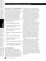
IGPs are used within an organization or an organization’s site. Exterior
Gateway Protocols (EGPs, as shown in Figure 7-5) are used between
organizations or sites, for example, a large wide area network (WAN),
such as the Internet or a large corporation’s intranet.
Figure 7-5 shows the role of EGP in Internet routing.
Figure 7-5 Role of EGP in Internet Routing
Many routing protocols pass route table information within an
autonomous system. Two popular protocols are the RIP and the Open
Shortest Path First (OSPF) Protocol.
RIP is a distance-vector protocol that exchanges route information
between IP routers. Distance-vector algorithms obtain their name from the
fact that they compute the least-cost path by using information that is
exchanged with other routers that describes reachable networks with their
distances in the form of hop counts.
Introducing Routing Protocol Types
7-8 Network Administration for the Solaris™ 9 Operating Environment
Copyright 2002 Sun Microsystems, Inc. All Rights Reserved. Enterprise Services, Revision A
OSPF is a link-state protocol. OSPF maintains a map of the network
topology instead of computing route paths that are based on distance
vectors in the way that RIP computes the route paths.
OSPF provides a global view of the network and provides the shortest
path choices on routes. The map on each OSPF router is updated
regularly.
Exterior Routing Protocols
An exterior routing protocol is a routing protocol that communicates
routes between autonomous systems. EGP and the Border Gateway
Protocol (BGP) are the two principal protocols that exchange route table
information among autonomous systems.
EGP was developed in the early 1980s. The concept of an autonomous
system developed out of the research and development of EGP.
BGP was developed in the mid 1990s to replace EGP. BGP replaces the
distance-vector algorithm of EGP with a path-vector algorithm. The path
vector that is implemented by BGP causes the route table information to
include a complete path (all autonomous system numbers) from the
source to the destination. This eliminates the possibility of looping
problems that might arise from complex network topologies, such as the
Internet. A loop is detected by BGP when the path it receives has an
autonomous system listed twice. If this occurs, BGP generates an error
condition.
Introducing the Route Table
Configuring Routing 7-9
Copyright 2002 Sun Microsystems, Inc. All Rights Reserved. Enterprise Services, Revision A
Introducing the Route Table
A system’s route table acts as a dynamic environment for storing route
entries for the system. The route table is referenced when a path to
another computer is required. The route table is often interrogated by
utilities when you troubleshoot connectivity issues.
Displaying the Route Table
To display the contents of a system’s route table without interpreting the
names of the systems, use the netstat utility with the -r and -n options.
The -r option causes the route table to be displayed. The -n option causes
the IP addresses to be displayed instead of resolving them to names.
sys11# netstat -rn
Routing Table: IPv4
Destination Gateway Flags Ref Use Interface
192.168.9.0 192.168.1.3 UG 1 0
192.168.1.0 192.168.1.1 U 1 51 qfe0
192.168.1.0 192.168.1.45 U 1 51 qfe1
192.168.1.0 192.168.1.1 U 1 0 qfe0:1
192.168.1.0 192.168.1.1 U 1 0 qfe1:1
192.168.2.0 192.168.1.3 UG 1 0
192.168.30.0 192.168.30.31 U 1 54 hme0
224.0.0.0 192.168.1.1 U 1 0 qfe0
127.0.0.1 127.0.0.1 UH 3 132 lo0
sys11#
Note – The 192.168.9.0 network was configured in Module 6,
‘‘Configuring Multipathing.”
Introducing the Route Table
7-10 Network Administration for the Solaris™ 9 Operating Environment
Copyright 2002 Sun Microsystems, Inc. All Rights Reserved. Enterprise Services, Revision A
Introducing Route Table Entries
Table 7-1 shows the route table fields and descriptions.
Table 7-1 Route Table Entries
Field Description
Destination The destination network or host address.
Gateway The system that delivers or forwards the datagram.
Flags The status of this route. This field uses the following
flags:
● U–The interface is up.
● H–The destination is a system, not a network.
● G–The delivery system is another system (an
indirect path).
● D–The entry was added dynamically by an
ICMP redirect.
Ref The current number of routes that share the same
network interface (Ethernet) address.
Use The number of datagrams that are using this route. For
the localhost entry, it is a snapshot of the number of
datagrams that are received.
Interface The local interface that reaches the destination.
Introducing the Route Table
Configuring Routing 7-11
Copyright 2002 Sun Microsystems, Inc. All Rights Reserved. Enterprise Services, Revision A
Figure 7-6 shows the network used in this module.
Figure 7-6 Classroom Network Diagram
Introducing the Route Table
7-12 Network Administration for the Solaris™ 9 Operating Environment
Copyright 2002 Sun Microsystems, Inc. All Rights Reserved. Enterprise Services, Revision A
Introducing Route Table Search Order
The kernel routing algorithm searches route table entries in the following
order:
1. The kernel routing algorithm checks the LAN for destination hosts.
The kernel extracts the destination IP address from the IP datagram
and computes the destination network number. The destination
network number is then compared with the network numbers of all
of the local interfaces (interfaces that are physically attached to the
system) for a match. If the destination network number matches that
of a local interface network number, the kernel encapsulates the IP
datagram inside an Ethernet frame and sends it through the
matching local interface for delivery.
2. The kernel routing algorithm checks the route table for a matching
host IP address.
The kernel searches the route table entries for a matching host IP
address. If an entry that matches the host IP address is found, the
kernel encapsulates the IP datagram inside an Ethernet frame and
sends the frame to the router that is associated with that destination.
3. The kernel routing algorithm checks the route table for a matching
network number.
The kernel searches the route table entries for a matching network
number. If a matching number is found, the kernel sets the
destination Ethernet address to that of the corresponding router and
delivers the frame to that router. The router that receives the frame
repeats the execution of the route algorithm, but leaves the
destination IP address unchanged.
4. The kernel routing algorithm checks for a default entry in the route
table.
The kernel searches the route table entries for a default entry. If a
default entry is found, the kernel encapsulates the datagram, sets
the destination Ethernet address to that of the default router, leaves
the destination IP address unchanged, and delivers the datagram
through the interface that is local to the default router.
5. If there is no route to the destination, the kernel routing algorithm
check generates an ICMP error message.
The kernel cannot forward the datagram, and an error message
from ICMP is generated. The error message states No route to
host or network is unreachable.
Introducing the Route Table
Configuring Routing 7-13
Copyright 2002 Sun Microsystems, Inc. All Rights Reserved. Enterprise Services, Revision A
Figure 7-7 shows the kernel routing process.
Figure 7-7 Kernel Routing Algorithm
Introducing the Route Table
7-14 Network Administration for the Solaris™ 9 Operating Environment
Copyright 2002 Sun Microsystems, Inc. All Rights Reserved. Enterprise Services, Revision A
Associating Network Name and Network Number
To associate a network name to a network number, edit the
/etc/inet/networks file.
The fields in the networks file are under the columns organized by
network name, network number, and nicknames.
sys11# tail -2 /etc/inet/networks
one 192.168.1 one
two 192.168.2 two
sys11#
When the networks file is modified, you can use the defined network
name in a command instead of a network address.
To add a route to the three network that is not defined in the
/etc/inet/networks file, perform a command similar to the following:
sys11# route add net 192.168.3.0 192.168.30.31
add net 192.168.3.0: gateway 192.168.30.31
sys11#
Note – Use of the metric argument in the route command is no longer
supported.
To add a route to the defined two network, perform a command similar to
the following:
sys11# route add net two 192.168.30.31
add net two: gateway 192.168.30.31
sys11#
Introducing the Route Table
Configuring Routing 7-15
Copyright 2002 Sun Microsystems, Inc. All Rights Reserved. Enterprise Services, Revision A
To view how defined networks are displayed in the output from the
netstat utility, use the netstat utility with the -r option:
sys11# netstat -r
Routing Table: IPv4
Destination Gateway Flags Ref Use Interface
192.168.9.0 sys13 UG 1 0
one sys11 U 1 53 qfe0
one sys11-dat-qfe1 U 1 53 qfe1
one sys11 U 1 0 qfe0:1
one sys11 U 1 0 qfe1:1
two sys13 UG 1 0
two sys11ext UG 1 0
192.168.3.0 sys11ext UG 1 0
192.168.30.0 sys11ext U 1 56 hme0
224.0.0.0 sys11 U 1 0 qfe0
localhost localhost UH 3 132 lo0
sys11#
Observe how the destination networks are now displayed by name
instead of by network address.
Configuring Static Routes
7-16 Network Administration for the Solaris™ 9 Operating Environment
Copyright 2002 Sun Microsystems, Inc. All Rights Reserved. Enterprise Services, Revision A
Configuring Static Routes
You can configure a route that does not change or time-out. This type of
route is called a static route.
Configuring Static Direct Routes
You can use the route utility to define a static direct route. A static route
is a route that is not automatically removed by the in.routed process if a
more efficient route is identified. The ifconfig utility initially builds the
direct route entries when the network interface is configured during
system startup. To view the results of the utility, perform the command:
sys11# netstat -r
Routing Table: IPv4
Destination Gateway Flags Ref Use Interface
sys12 sys11 UH 1 0 qfe0
one sys11 U 1 75 qfe0
one sys11-dat-qfe1 U 1 75 qfe1
one sys11 U 1 0 qfe0:1
one sys11 U 1 0 qfe1:1
192.168.30.0 sys11ext U 1 77 hme0
224.0.0.0 sys11 U 1 0 qfe0
localhost localhost UH 3 132 lo0
sys11#
The localhost entry in the local routing table is a loopback route to the
local host that is created when the lo0 pseudo interface is configured.
Configuring the /etc/defaultrouter File
A default route is a route table entry that defines the default routers to use
if no other specific route is available. Default route entries can be either
static entries or dynamic entries. The default routers must be reliable. You
do not need to define every reachable network because datagrams that are
addressed to non-local destinations use a default router in the absence of
an explicit route.
Configuring Static Routes
Configuring Routing 7-17
Copyright 2002 Sun Microsystems, Inc. All Rights Reserved. Enterprise Services, Revision A
You can define default routers by creating the /etc/defaultrouter file
that contains host name entries or IP address entries that identify one or
more routers. You must use host names that exist in the system’s
/etc/inet/hosts file because no name-resolution services are available
at the time that this file is initially read at system boot time. This file
prevents the startup of the in.routed and in.rdisc dynamic router
processes. The in.rdisc process adds default route table entries
dynamically.
Some advantages of default routing are:
● The /etc/defaultrouter file prevents unneeded routing processes
from starting.
● The default entries result in a smaller route table, which reduces the
processing time spent on each IP datagram.
● Multiple default routers can be identified, which eliminate single
points-of-failure within a network.
● Systems that use default route entries do not depend on actual
routing protocols.
Some disadvantages of default routing are:
● The default entries created by the /etc/defaultrouter file or the
route utility are always present, even when the default router is not
available. The system does not learn about other possible routes.
● All systems must have a local /etc/defaultrouter file properly
configured because this file cannot be administered by a name
service. This can be an administrative problem on large, evolving
networks.
Configuring the /etc/gateways File
The in.routed router process reads the optional /etc/gateways file at
initialization to possibly add additional static routes. This is another way
to add a static (passive) route. The fields in the /etc/gateways file are:
net|host
destination
gateway
gateway
metric
hops
passive|active
For example:
sys11# cat /etc/gateways
net 192.168.4.0 gateway sys41ext metric 2 passive
sys11#
Configuring Static Routes
7-18 Network Administration for the Solaris™ 9 Operating Environment
Copyright 2002 Sun Microsystems, Inc. All Rights Reserved. Enterprise Services, Revision A
Note – It is a better practice to use the IP address rather than the host
name, which might not be able to be resolved.
Use directives in the gateways file to prevent RIP (in.routed process)
datagrams from either going in to or going out of the specified interface.
Use the noripin directive when you want your system to ignore route
information that can be received on a specific interface. For example, to
ignore route information received on the qfe3 interface, use the following
noripin directive in the gateways file:
noripin qfe3
Use the noripout directive if you have a multihomed system (system
with multiple physical interfaces) and do not want your system to act as a
router and advertise routes. For example, to ensure that no route
information is sent out of the qfe3 interface, use the following noripout
directive in the gateways file:
noripout qfe3
You can choose to use both the noripin and noripout directives or
replace them with a single norip directive. For example, to ignore route
information and to not allow route information to be sent out of the qfe3
interface, use the following norip directive in the gateways file:
norip qfe3
Refer to the in.routed man page for more information on the gateways
file.
Configuring Manual Static Routes
The route utility enables manual manipulation of the route table. Its basic
format is:
route add|delete
destination gateway
To add a direct static route between the sys11 and sys12 systems,
perform a command similar to the following:
sys11# route add sys12 sys11
add host sys12: gateway sys11
sys11#
Configuring Static Routes
Configuring Routing 7-19
Copyright 2002 Sun Microsystems, Inc. All Rights Reserved. Enterprise Services, Revision A
To delete the route between sys12 and sys11, perform a command
similar to the following:
sys11# route delete sys12 sys11
delete host sys12: gateway sys11
sys11#
To define a default route using the instructor system, perform a
command similar to the following:
sys11# route add default instructor
add net default: gateway instructor
sys11#
To retrieve information about a specific route, use the route utility. For
example, to retrieve information about the default route, perform a
command similar to the following:
sys11# route get default
route to: default
destination: default
mask: default
gateway: instructor
interface: hme0
flags: <UP,GATEWAY,DONE,STATIC>
recvpipe sendpipe ssthresh rtt,ms rttvar,ms hopcount mtu expire
0 0 0 0 0 0 1500 0
sys11#
To change the route table, use the change option with the route utility.
For example, to change the default route from instructor to sys41,
perform a command similar to the following:
sys11# route change default sys41
change net default: gateway sys41
sys11#
To continuously report any changes to the route table, route lookup
misses, or suspected network partitionings, use the route utility. For
example, when a route is deleted, to receive the following output, perform
the route monitor command:
sys11# route monitor
got message of size 124
RTM_DELETE: Delete Route: len 124, pid: 633, seq 1, errno 0,
flags:<UP,GATEWAY,DONE,STATIC>
locks: inits:
sockaddrs: <DST,GATEWAY,NETMASK>
192.168.3.0 sys11ext 255.255.255.0
Configuring Static Routes
7-20 Network Administration for the Solaris™ 9 Operating Environment
Copyright 2002 Sun Microsystems, Inc. All Rights Reserved. Enterprise Services, Revision A
To flush (remove) the route table of all gateway entries, use the flush
option with the route utility. For example, to flush the route table,
perform the route flush command:
sys11# route flush
192.168.9 sys13 done
two sys13 done
two sys11ext done
default 172.20.4.248 done
sys11#
To cause the route table to flush before the remaining options are
evaluated, use the flush option in combination with other options. For
example, to flush the route table of gateways and to add a route to the
192.168.4.0 network, perform a command similar to the following:
sys11# route -f add net 192.168.4.0 sys11ext
add net 192.168.4.0: gateway sys11ext
sys11#
To manually add a route to the multicast address range of 224 through
239, perform the command:
sys11# route add 224.0/4 ‘uname -n‘
Note – You can find the command syntax in the /etc/rc2.d/S72inetsvc
startup file.
To define a route that uses a specific netmask to support a network, use
the netmask option with the route utility. For example, to add a route to
the 192.168.3.0 network that uses a netmask of 255.255.255.224,
perform the command:
sys11# route add net 192.168.3.0 sys31ext -netmask 255.255.255.224
add net 192.168.3.0: gateway sys31ext
sys11#
Configuring Static Routes
Configuring Routing 7-21
Copyright 2002 Sun Microsystems, Inc. All Rights Reserved. Enterprise Services, Revision A
To achieve the same results in a more concise way, specify the length of
the subnet mask after the destination. For example, enter:
192.168.3.0/27
The 255.255.255.224 netmask for the 192.168.3.0 network is
11111111.11111111.11111111.11100000 in binary format. There are
twenty-seven 1s in the binary netmask, hence the /27 after the network
address. A command similar to the following is identical to the preceding
command example:
sys11# route add net 192.168.3.0/27 sys31ext
add net 192.168.3.0/27: gateway sys31ext
sys11#
Note – The in.routed process does not detect any route table changes
that are performed by other programs on the machine, for example, routes
that are added, deleted, or flushed as a result of the route utility.
Therefore, do not perform these types of changes while the in.routed
process is running. Instead, shut down the in.routed process, make the
required changes, and then restart the in.routed process. This ensures
that the in.routed process learns of any changes.
Using the RDISC Protocol
The RDISC Protocol sends and receives router advertisement messages
pertaining to default routes. RFC 1256 specifies the format of related
ICMP messages. The in.rdisc process implements the RDISC Protocol.
Routers that run the in.rdisc process with the -r option advertise their
presence using the 224.0.0.1 multicast address every 600 seconds
(10 minutes). Non-routers, running the in.rdisc process that is started
with the -s option, listen to the 224.0.0.1 multicast address for these
router advertisement messages. The in.rdisc process builds a default
route entry for each router from which an advertisement is received.
Some advantages of the RDISC Protocol are that it:
● Is routing protocol independent
● Uses a multicast address
● Results in small route tables
● Provides redundancy through multiple default route entries
Configuring Static Routes
7-22 Network Administration for the Solaris™ 9 Operating Environment
Copyright 2002 Sun Microsystems, Inc. All Rights Reserved. Enterprise Services, Revision A
Some disadvantages of the RDISC protocol are:
● An advertisement period of 10 minutes can result in a black hole. A
black hole is the time period in which a router path is present in the
table, but the router is not actually available. The default lifetime for
a non-advertised route is 30 minutes (three times the advertising
time interval).
● Routers must still run a routing protocol, such as RIP, to learn about
other networks. The RDISC (in.rdisc) Protocol provides a default
route from hosts to routers, not between routers.
The basic syntax for the in.rdisc process is:
/usr/sbin/in.rdisc [-s]
/usr/sbin/in.rdisc -r [-T
interval
]
The first syntax example is used by non-router systems and is called the
host mode. The -s option causes the process to solicit input from routers.
The second syntax example is used by routers and is called the router
mode. The -r options causes the in.rdisc process to advertise the
system as a router.
The in.rdisc process sends three solicitation messages when it starts to
quickly discover available routers.
To change the interval for router advertisements to 100 seconds from the
default of 600 seconds, use the following command:
sys11# /usr/sbin/in.rdisc -r -T 100
Configuring Dynamic Routing
Configuring Routing 7-23
Copyright 2002 Sun Microsystems, Inc. All Rights Reserved. Enterprise Services, Revision A
Configuring Dynamic Routing
RIP is a routing protocol that is commonly used on computer systems to
provide dynamic routing. RIP version 1 is bundled with the Solaris OE.
RIP is an Application layer protocol.
RIP Version 1
RIP version 1 is a distance-vector protocol that exchanges route
information between IP routers. RIP version 1 does not support VLSM.
Distance-Vector Protocols
Distance-vector algorithms compute the least-cost path of a route by using
information that is exchanged with other routers. This information
describes how far away (in distance) reachable networks are from the
sending or receiving system. This distance is measured by a metric known
as a hop. The total number of hops is called the hop count. The efficiency
of a route is determined by its distance from the source to the destination.
RIP maintains only the best route to a destination. When multiple paths to
a destination exist, only the first path with the lowest hop count is
maintained. Figure 7-8 shows the least hop count between a source host
and a destination host.
Figure 7-8 Least Hop Count
RIP specifies a number of features that make its operation more stable in
the face of rapid network topology changes. These stability features
include a hop-count limit, hold-down states, split horizons, triggered
updates, and route poisoning.
Configuring Dynamic Routing
7-24 Network Administration for the Solaris™ 9 Operating Environment
Copyright 2002 Sun Microsystems, Inc. All Rights Reserved. Enterprise Services, Revision A
Hop-Count Limits
RIP permits a maximum hop count of 15. A destination greater than
15 hops away is tagged as unreachable. The maximum hop count of RIP
greatly restricts its use in large networks but prevents a problem called
“count to infinity” from causing endless network routing loops.
Hold-Down States
Hold-down states prevent regular update messages from inappropriately
reinstating a route that has gone bad. When a route goes down,
neighboring routers detect this condition. These routers then calculate
new routes and send route update messages to inform their neighbors of
the route change. This activity begins a wave of route updates that filter
through the network. These updates do not instantly arrive at every
network device. It is possible that a device that has yet to be informed of
a network failure can send a regular update message (indicating that a
route that has just gone down is still available) to a device that has just
been notified of the network failure. In this case, the latter device now
contains (and potentially advertises) incorrect route information.
Hold-down states tell routers to hold down any changes that can affect
recently removed routes for a specified period of time. The hold-down
period is usually calculated to be just greater than the period of time that
is necessary to update the entire network with a route change.
Split Horizons
Split horizons derive from the fact that it is never useful to send
information about a route back in the direction from which it came. The
split-horizon rule prohibits this from happening. This helps prevent
two-node routing loops.
Triggered Updates
Triggered updates quickly propagate changing route information
throughout the network. As the router becomes aware that new routes are
available or that existing routes are not available, it immediately
advertises this information rather than waiting until the next 30-second
(default) advertisement interval occurs.
Configuring Dynamic Routing
Configuring Routing 7-25
Copyright 2002 Sun Microsystems, Inc. All Rights Reserved. Enterprise Services, Revision A
Route Poisoning
When a router learns that a destination is no longer available, it issues a
triggered update for that destination. This update includes a hop-count
advertisement of 16. All other hosts and routers consider the destination
as unreachable, and the hosts and routers remove the route entry. This is
to ensure that other systems do not attempt to use the “bad” route.
The in.routed Process
The RIP daemon is implemented by the /usr/sbin/in.routed process.
The /usr/sbin/in.routed process causes a system to broadcast its own
route information if more than one external interface exists. A router
broadcasts to the networks to which it is directly connected every
30 seconds. You cannot change this time interval. All hosts receive the
broadcast, but only those hosts that run the in.routed process access the
information. Routers run the in.routed process with the -s option, while
non-routers run the in.routed process with the -q option.
The in.routed Options
The basic syntax for starting the in.routed process includes:
/usr/sbin/in.routed [ -qstv ] [ logfile ]
The in.routed process is started at boot time by the
/etc/init.d/inetinit script.
To start the in.routed process in the quiet mode to stop it from
broadcasting updates every 30 seconds, use the -q option:
# /usr/sbin/in.routed -q
To force the in.routed process to broadcast every 30 seconds, use the
-s option:
# /usr/sbin/in.routed -s
To log the actions of the in.routed process, perform the command:
# /usr/sbin/in.routed -s -v /var/adm/routelog
Configuring Dynamic Routing
7-26 Network Administration for the Solaris™ 9 Operating Environment
Copyright 2002 Sun Microsystems, Inc. All Rights Reserved. Enterprise Services, Revision A
The /var/adm/routelog file is not created or cleared out automatically.
To log the actions of the in.routed process to the standard output, use
the -t option in combination with either the -s or the -q options:
# /usr/sbin/in.routed -s -t
ICMP (Routing) Redirect
ICMP provides control and error messages. ICMP on a router or gateway
attempts to send reports of problems to the original source. ICMP
datagrams are always encapsulated in IP.
ICMP redirects occur when a system uses more than one default route. If
the router determines a more efficient route, or if there is only one way to
forward the datagram, it redirects the datagram using the better or only
route and reports that route to the sender. Figure 7-9 on page 7-27 shows
an ICMP redirect process where the sys21 system needs to communicate
with the server1 system and has a default route of sys11. The
information does reach the server1 system and the sys11 system sends
an ICMP redirect to the sys21 system, telling it that the best route to the
server1 system is through the instructor system.
The sending system’s route table is updated with the new information.
The drawback to this method of routing is that for every ICMP redirect,
there is a separate entry in the sending system’s route table. This action
can lead to a large route table. However, this method of routing also
ensures that the datagrams that are going to all reachable hosts are taking
the shortest route.
Caution – An attacker might forge redirect errors to install false routes,
which might initiate a denial of service attack if the newly specified router
is not a router at all. There are rules governing valid redirect errors, all of
which can be spoofed easily. Use this ndd command to ignore IPv4 ICMP
redirect errors: ndd -set /dev/ip ip_ignore_redirect 1.
Refer to the Sun BluePrints™ document Solaris Operating Environment
Network Settings for Security, available at:
/>network-updt1.pdf.
Configuring Dynamic Routing
Configuring Routing 7-27
Copyright 2002 Sun Microsystems, Inc. All Rights Reserved. Enterprise Services, Revision A
Figure 7-9 ICMP Redirect
Introducing CIDR
7-28 Network Administration for the Solaris™ 9 Operating Environment
Copyright 2002 Sun Microsystems, Inc. All Rights Reserved. Enterprise Services, Revision A
Introducing CIDR
The rapid growth of the Internet in the early 1990s created concerns about
the ability to scale and support future growth. The most severe problems
are:
● Impending depletion of Class B networks
● Increasing the size of route tables
Depletion of Class B networks creates a problem for large organizations
because Class C addresses with 254 as their maximum number of host
addresses are not large enough. Assigning multiple Class C networks to
companies will, over time, dramatically increase the number of routes in
the route table. Large route tables cause poor router performance because
the router spends excessive time performing address lookups.
Purpose of CIDR
A task force was created by the Internet Engineering Task Force (IETF) to
develop a solution to these problems. That solution became known as
CIDR, or supernetting, and is a way to more efficiently use the IP address
space. CIDR is documented in RFC 1517, RFC 1518, RFC 1519, and
RFC 1520. Three important features of CIDR that address scalability and
growth issues for the Internet are:
● Elimination of network classes (Class A, Class B, and Class C)
● Block address allocation
● Hierarchical routing
Operation of CIDR
CIDR uses classless addresses in that it uses netmasks that are referred to
as network prefixes to create varying network sizes. The network prefix is
expressed in the following notation: X.X.X.X/18, which is equivalent to
the netmask of 255.255.192.0. The first 18 bits identify the network, and
the remaining 14 bits identify the host.
Introducing CIDR
Configuring Routing 7-29
Copyright 2002 Sun Microsystems, Inc. All Rights Reserved. Enterprise Services, Revision A
Figure 7-10 shows an example of a CIDR prefix.
Figure 7-10 CIDR Prefix
This use of netmasks means addresses can be supernetted as well as
subnetted. Supernetting is the combining of two or more contiguous
network addresses. CIDR and VLSM are similar because they both allow a
portion of the IP address space to be recursively divided into successively
smaller pieces. With VLSM, the recursion occurs on an address space that
is assigned to an organization and is invisible to the Internet. CIDR occurs
at the Internet service provider (ISP) level and applies VLSM concepts to
the Internet. With CIDR, the largest ISPs are allocated blocks of address
space, which they then assign in subset address blocks to smaller ISPs.
These smaller ISPs can then supply a even smaller subset of addresses to
a customer or private organization.
The route table entry for each ISP or organization reflects the first address
in the block assigned to it, for example, 204.106.8.0/22, even though
there can be additional network addresses that are associated with the
block. A range of CIDR addresses is known as a CIDR block. This support
of network addresses eliminates the number of entries required in the
backbone route tables.
Introducing CIDR
7-30 Network Administration for the Solaris™ 9 Operating Environment
Copyright 2002 Sun Microsystems, Inc. All Rights Reserved. Enterprise Services, Revision A
Consider an ISP that requires IP addresses for 1000 clients. Based on
254 clients per Class C network, the ISP requires four Class C networks.
You can supernet the four Class C networks as:
● 204.106.8.0
● 204.106.9.0
● 204.106.10.0
● 204.106.11.0
Supernetting these addresses works because all four address ranges begin
with the same 22-bit prefix of 1100110001101010000010. Therefore, a
single route to this prefix can reach all four address ranges.
Figure 7-11 shows an example of supernetting.
Figure 7-11 Supernetting Example
Introducing CIDR
Configuring Routing 7-31
Copyright 2002 Sun Microsystems, Inc. All Rights Reserved. Enterprise Services, Revision A
Figure 7-12 shows the network addresses that result from applying
different network prefixes.
Figure 7-12 CIDR Network Addresses