Operating Systems Design and Implementation, Third Edition phần 5 potx
Bạn đang xem bản rút gọn của tài liệu. Xem và tải ngay bản đầy đủ của tài liệu tại đây (2.27 MB, 93 trang )
[Page 374 (continued)]
4.1. Basic Memory Management
Memory management systems can be divided into two basic classes: those that move processes back and forth
between main memory and disk during execution (swapping and paging), and those that do not. The latter are
simpler, so we will study them first. Later in the chapter we will examine swapping and paging. Throughout
this chapter the reader should keep in mind that swapping and paging are largely artifacts caused by the lack
of sufficient main memory to hold all programs and data at once. If main memory ever gets so large that there
is truly enough of it, the arguments in favor of one kind of memory management scheme or another may
become obsolete.
On the other hand, as mentioned above, software seems to grow as fast as memory, so efficient memory
management may always be needed. In the 1980s, there were many universities that ran a timesharing system
with dozens of (more-or-less satisfied) users on a 4 MB VAX. Now Microsoft recommends having at least
128 MB for a single-user Windows XP system. The trend toward multimedia puts even more demands on
memory, so good memory management is probably going to be needed for the next decade at least.
4.1.1. Monoprogramming without Swapping or Paging
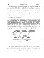
The simplest possible memory management scheme is to run just one program at a time, sharing the memory
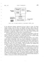
between that program and the operating system. Three variations on this theme are shown in Fig. 4-1. The
operating system may be at the bottom of memory in RAM (Random Access Memory), as shown in Fig.
4-1(a), or it may be in ROM (Read-Only Memory) at the top of memory, as shown in Fig. 4-1(b), or the
device drivers may be at the top of memory in a ROM and the rest of the system in RAM down below, as
shown in Fig. 4-1(c). The first model was formerly used on mainframes and minicomputers but is rarely used
any more. The second model is used on some palmtop computers and embedded systems. The third model
was used by early personal computers (e.g., running MS-DOS), where the portion of the system in the ROM is
called the BIOS (Basic Input Output System).
[Page 375]
Figure 4-1. Three simple ways of organizing memory with an operating system and one user process. Other
possibilities also exist.
1
1
Simpo PDF Merge and Split Unregistered Version -
When the system is organized in this way, only one process at a time can be running. As soon as the user
types a command, the operating system copies the requested program from disk to memory and executes it.
When the process finishes, the operating system displays a prompt character and waits for a new command.
When it receives the command, it loads a new program into memory, overwriting the first one.
4.1.2. Multiprogramming with Fixed Partitions
Except on very simple embedded systems, monoprogramming is hardly used any more. Most modern systems
allow multiple processes to run at the same time. Having multiple processes running at once means that when
one process is blocked waiting for I/O to finish, another one can use the CPU. Thus multiprogramming
increases the CPU utilization. Network servers always have the ability to run multiple processes (for different
clients) at the same time, but most client (i.e., desktop) machines also have this ability nowadays.
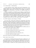
The easiest way to achieve multiprogramming is simply to divide memory up into n (possibly unequal)
partitions. This partitioning can, for example, be done manually when the system is started up.
When a job arrives, it can be put into the input queue for the smallest partition large enough to hold it. Since
the partitions are fixed in this scheme, any space in a partition not used by a job is wasted while that job runs.
In Fig. 4-2(a) we see how this system of fixed partitions and separate input queues looks.
Figure 4-2. (a) Fixed memory partitions with separate input queues for each partition. (b) Fixed memory partitions
with a single input queue. (This item is displayed on page 376 in the print version)
[View full size image]
The disadvantage of sorting the incoming jobs into separate queues becomes apparent when the queue for a
large partition is empty but the queue for a small partition is full, as is the case for partitions 1 and 3 in Fig.
4-2(a). Here small jobs have to wait to get into memory, even though plenty of memory is free. An alternative
organization is to maintain a single queue as in Fig. 4-2(b). Whenever a partition becomes free, the job closest
to the front of the queue that fits in it could be loaded into the empty partition and run. Since it is undesirable
to waste a large partition on a small job, a different strategy is to search the whole input queue whenever a
2
2
Simpo PDF Merge and Split Unregistered Version -
partition becomes free and pick the largest job that fits. Note that the latter algorithm discriminates against
small jobs as being unworthy of having a whole partition, whereas usually it is desirable to give the smallest
jobs (often interactive jobs) the best service, not the worst.
[Page 376]
One way out is to have at least one small partition around. Such a partition will allow small jobs to run
without having to allocate a large partition for them.
Another approach is to have a rule stating that a job that is eligible to run may not be skipped over more than
k times. Each time it is skipped over, it gets one point. When it has acquired k points, it may not be skipped
again.
This system, with fixed partitions set up by the operator in the morning and not changed thereafter, was used
by OS/360 on large IBM mainframes for many years. It was called MFT (Multiprogramming with a Fixed
number of Tasks or OS/MFT). it is simple to understand and equally simple to implement: incoming jobs are
queued until a suitable partition is available, at which time the job is loaded into that partition and run until it
terminates. However, nowadays, few, if any, operating systems, support this model, even on mainframe batch
systems.
[Page 377]
4.1.3. Relocation and Protection
Multiprogramming introduces two essential problems that must be solved relocation and protection. Look at
Fig. 4-2. From the figure it is clear that different jobs will be run at different addresses. When a program is
linked (i.e., the main program, user-written procedures, and library procedures are combined into a single
address space), the linker must know at what address the program will begin in memory.
For example, suppose that the first instruction is a call to a procedure at absolute address 100 within the binary
file produced by the linker. If this program is loaded in partition 1 (at address 100K), that instruction will
jump to absolute address 100, which is inside the operating system. What is needed is a call to 100K + 100. If
the program is loaded into partition 2, it must be carried out as a call to 200K + 100, and so on. This problem
is known as the relocation problem.
One possible solution is to actually modify the instructions as the program is loaded into memory. Programs
loaded into partition 1 have 100K added to each address, programs loaded into partition 2 have 200K added to
addresses, and so forth. To perform relocation during loading like this, the linker must include in the binary
program a list or bitmap telling which program words are addresses to be relocated and which are opcodes,
constants, or other items that must not be relocated. OS/MFT worked this way.
Relocation during loading does not solve the protection problem. A malicious program can always construct a
new instruction and jump to it. Because programs in this system use absolute memory addresses rather than
addresses relative to a register, there is no way to stop a program from building an instruction that reads or
writes any word in memory. In multiuser systems, it is highly undesirable to let processes read and write
memory belonging to other users.
The solution that IBM chose for protecting the 360 was to divide memory into blocks of 2-KB bytes and
assign a 4-bit protection code to each block. The PSW (Program Status Word) contained a 4-bit key. The 360
hardware trapped any attempt by a running process to access memory whose protection code differed from the
PSW key. Since only the operating system could change the protection codes and key, user processes were
3
3
Simpo PDF Merge and Split Unregistered Version -
prevented from interfering with one another and with the operating system itself.
An alternative solution to both the relocation and protection problems is to equip the machine with two special
hardware registers, called the base and limit registers. When a process is scheduled, the base register is loaded
with the address of the start of its partition, and the limit register is loaded with the length of the partition.
Every memory address generated automatically has the base register contents added to it before being sent to
memory. Thus if the base register contains the value 100K, a CALL 100 instruction is effectively turned into a
CALL 100K + 100 instruction, without the instruction itself being modified. Addresses are also checked
against the limit register to make sure that they do not attempt to address memory outside the current partition.
The hardware protects the base and limit registers to prevent user programs from modifying them.
[Page 378]
A disadvantage of this scheme is the need to perform an addition and a comparison on every memory
reference. Comparisons can be done fast, but additions are slow due to carry propagation time unless special
addition circuits are used.
The CDC 6600the world's first supercomputerused this scheme. The Intel 8088 CPU used for the original
IBM PC used a slightly weaker version of this schemebase registers, but no limit registers. Few computers use
it now.
4
4
Simpo PDF Merge and Split Unregistered Version -
[Page 378 (continued)]
4.2. Swapping
With a batch system, organizing memory into fixed partitions is simple and effective. Each job is loaded into
a partition when it gets to the head of the queue. It stays in memory until it has finished. As long as enough
jobs can be kept in memory to keep the CPU busy all the time, there is no reason to use anything more
complicated.
With timesharing systems or graphics-oriented personal computers, the situation is different. Sometimes there
is not enough main memory to hold all the currently active processes, so excess processes must be kept on
disk and brought in to run dynamically.
Two general approaches to memory management can be used, depending (in part) on the available hardware.
The simplest strategy, called swapping, consists of bringing in each process in its entirety, running it for a
while, then putting it back on the disk. The other strategy, called virtual memory, allows programs to run even
when they are only partially in main memory. Below we will study swapping; in Sec. 4.3 we will examine
virtual memory.
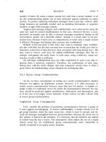
The operation of a swapping system is illustrated in Fig. 4-3. Initially, only process A is in memory. Then
processes B and C are created or swapped in from disk. In Fig. 4-3(d) A is swapped out to disk. Then D
comes in and B goes out. Finally A comes in again. Since A is now at a different location, addresses contained
in it must be relocated, either by software when it is swapped in or (more likely) by hardware during program
execution.
Figure 4-3. Memory allocation changes as processes come into memory and leave it. The shaded regions are
unused memory. (This item is displayed on page 379 in the print version)
[View full size image]
The main difference between the fixed partitions of Fig. 4-2 and the variable partitions of Fig. 4-3 is that the
number, location, and size of the partitions vary dynamically in the latter as processes come and go, whereas
they are fixed in the former. The flexibility of not being tied to a fixed number of partitions that may be too
large or too small improves memory utilization, but it also complicates allocating and deallocating memory,
as well as keeping track of it.
When swapping creates multiple holes in memory, it is possible to combine them all into one big one by
1
1
Simpo PDF Merge and Split Unregistered Version -
moving all the processes downward as far as possible. This technique is known as memory compaction. It is
usually not done because it requires a lot of CPU time. For example, on a 1-GB machine that can copy at a
rate of 2 GB/sec (0.5 nsec/byte) it takes about 0.5 sec to compact all of memory. That may not seem like much
time, but it would be noticeably disruptive to a user watching a video stream.
[Page 379]
A point that is worth making concerns how much memory should be allocated for a process when it is created
or swapped in. If processes are created with a fixed size that never changes, then the allocation is simple: the
operating system allocates exactly what is needed, no more and no less.
If, however, processes' data segments can grow, for example, by dynamically allocating memory from a heap,
as in many programming languages, a problem occurs whenever a process tries to grow. If a hole is adjacent
to the process, it can be allocated and the process can be allowed to grow into the hole. On the other hand, if
the process is adjacent to another process, the growing process will either have to be moved to a hole in
memory large enough for it, or one or more processes will have to be swapped out to create a large enough
hole. If a process cannot grow in memory and the swap area on the disk is full, the process will have to wait or
be killed.
If it is expected that most processes will grow as they run, it is probably a good idea to allocate a little extra
memory whenever a process is swapped in or moved, to reduce the overhead associated with moving or
swapping processes that no longer fit in their allocated memory. However, when swapping processes to disk,
only the memory actually in use should be swapped; it is wasteful to swap the extra memory as well. In Fig.
4-4(a) we see a memory configuration in which space for growth has been allocated to two processes.
Figure 4-4. (a) Allocating space for a growing data segment. (b) Allocating space for a growing stack and a
growing data segment. (This item is displayed on page 380 in the print version)
[View full size image]
If processes can have two growing segments, for example, the data segment being used as a heap for variables
that are dynamically allocated and released and a stack segment for the normal local variables and return
2
2
Simpo PDF Merge and Split Unregistered Version -
addresses, an alternative arrangement suggests itself, namely that of Fig. 4-4(b). In this figure we see that each
process illustrated has a stack at the top of its allocated memory that is growing downward, and a data
segment just beyond the program text that is growing upward. The memory between them can be used for
either segment. If it runs out, either the process will have to be moved to a hole with sufficient space, swapped
out of memory until a large enough hole can be created, or killed.
[Page 380]
4.2.1. Memory Management with Bitmaps
When memory is assigned dynamically, the operating system must manage it. In general terms, there are two
ways to keep track of memory usage: bitmaps and free lists. In this section and the next one we will look at
these two methods in turn.
With a bitmap, memory is divided up into allocation units, perhaps as small as a few words and perhaps as
large as several kilobytes. Corresponding to each allocation unit is a bit in the bitmap, which is 0 if the unit is
free and 1 if it is occupied (or vice versa). Figure 4-5 shows part of memory and the corresponding bitmap.
Figure 4-5. (a) A part of memory with five processes and three holes. The tick marks show the memory allocation
units. The shaded regions (0 in the bitmap) are free. (b) The corresponding bitmap. (c) The same information as a
list. (This item is displayed on page 381 in the print version)
[View full size image]
The size of the allocation unit is an important design issue. The smaller the allocation unit, the larger the
bitmap. However, even with an allocation unit as small as 4 bytes, 32 bits of memory will require only 1 bit of
the map. A memory of 32n bits will use n map bits, so the bitmap will take up only 1/33 of memory. If the
allocation unit is chosen large, the bitmap will be smaller, but appreciable memory may be wasted in the last
unit of the process if the process size is not an exact multiple of the allocation unit.
[Page 381]
A bitmap provides a simple way to keep track of memory words in a fixed amount of memory because the
size of the bitmap depends only on the size of memory and the size of the allocation unit. The main problem
with it is that when it has been decided to bring a k unit process into memory, the memory manager must
search the bitmap to find a run of k consecutive 0 bits in the map. Searching a bitmap for a run of a given
length is a slow operation (because the run may straddle word boundaries in the map); this is an argument
against bitmaps.
3
3
Simpo PDF Merge and Split Unregistered Version -
4.2.2. Memory Management with Linked Lists
Another way of keeping track of memory is to maintain a linked list of allocated and free memory segments,
where a segment is either a process or a hole between two processes. The memory of Fig. 4-5(a) is
represented in Fig. 4-5(c) as a linked list of segments. Each entry in the list specifies a hole (H) or process (P),
the address at which it starts, the length, and a pointer to the next entry.
In this example, the segment list is kept sorted by address. Sorting this way has the advantage that when a
process terminates or is swapped out, updating the list is straightforward. A terminating process normally has
two neighbors (except when it is at the very top or very bottom of memory). These may be either processes or
holes, leading to the four combinations shown in Fig. 4-6. In Fig. 4-6(a) updating the list requires replacing a
P by an H. In Fig. 4-6(b) and also in Fig. 4-6(c), two entries are coalesced into one, and the list becomes one
entry shorter. In Fig. 4-6(d), three entries are merged and two items are removed from the list. Since the
process table slot for the terminating process will normally point to the list entry for the process itself, it may
be more convenient to have the list as a double-linked list, rather than the single-linked list of Fig. 4-5(c). This
structure makes it easier to find the previous entry and to see if a merge is possible.
[Page 382]
Figure 4-6. Four neighbor combinations for the terminating process, X.
When the processes and holes are kept on a list sorted by address, several algorithms can be used to allocate
memory for a newly created process (or an existing process being swapped in from disk). We assume that the
memory manager knows how much memory to allocate. The simplest algorithm is first fit. The process
manager scans along the list of segments until it finds a hole that is big enough. The hole is then broken up
into two pieces, one for the process and one for the unused memory, except in the statistically unlikely case of
an exact fit. First fit is a fast algorithm because it searches as little as possible.
A minor variation of first fit is next fit. It works the same way as first fit, except that it keeps track of where it
is whenever it finds a suitable hole. The next time it is called to find a hole, it starts searching the list from the
place where it left off last time, instead of always at the beginning, as first fit does. Simulations by Bays
(1977) show that next fit gives slightly worse performance than first fit.
Another well-known algorithm is best fit. Best fit searches the entire list and takes the smallest hole that is
adequate. Rather than breaking up a big hole that might be needed later, best fit tries to find a hole that is close
to the actual size needed.
4
4
Simpo PDF Merge and Split Unregistered Version -
As an example of first fit and best fit, consider Fig. 4-5 again. If a block of size 2 is needed, first fit will
allocate the hole at 5, but best fit will allocate the hole at 18.
Best fit is slower than first fit because it must search the entire list every time it is called. Somewhat
surprisingly, it also results in more wasted memory than first fit or next fit because it tends to fill up memory
with tiny, useless holes. First fit generates larger holes on the average.
To get around the problem of breaking up nearly exact matches into a process and a tiny hole, one could think
about worst fit, that is, always take the largest available hole, so that the hole broken off will be big enough to
be useful. Simulation has shown that worst fit is not a very good idea either.
[Page 383]
All four algorithms can be speeded up by maintaining separate lists for processes and holes. In this way, all of
them devote their full energy to inspecting holes, not processes. The inevitable price that is paid for this
speedup on allocation is the additional complexity and slowdown when deallocating memory, since a freed
segment has to be removed from the process list and inserted into the hole list.
If distinct lists are maintained for processes and holes, the hole list may be kept sorted on size, to make best fit
faster. When best fit searches a list of holes from smallest to largest, as soon as it finds a hole that fits, it
knows that the hole is the smallest one that will do the job, hence the best fit. No further searching is needed,
as it is with the single list scheme. With a hole list sorted by size, first fit and best fit are equally fast, and next
fit is pointless.
When the holes are kept on separate lists from the processes, a small optimization is possible. Instead of
having a separate set of data structures for maintaining the hole list, as is done in Fig. 4-5(c), the holes
themselves can be used. The first word of each hole could be the hole size, and the second word a pointer to
the following entry. The nodes of the list of Fig. 4-5(c), which require three words and one bit (P/H), are no
longer needed.
Yet another allocation algorithm is quick fit, which maintains separate lists for some of the more common
sizes requested. For example, it might have a table with n entries, in which the first entry is a pointer to the
head of a list of 4-KB holes, the second entry is a pointer to a list of 8-KB holes, the third entry a pointer to
12-KB holes, and so on. Holes of say, 21 KB, could either be put on the 20-KB list or on a special list of
odd-sized holes. With quick fit, finding a hole of the required size is extremely fast, but it has the same
disadvantage as all schemes that sort by hole size, namely, when a process terminates or is swapped out,
finding its neighbors to see if a merge is possible is expensive. If merging is not done, memory will quickly
fragment into a large number of small holes into which no processes fit.
5
5
Simpo PDF Merge and Split Unregistered Version -
6
6
Simpo PDF Merge and Split Unregistered Version -
[Page 383 (continued)]
4.3. Virtual Memory
Many years ago people were first confronted with programs that were too big to fit in the
available memory. The solution usually adopted was to split the program into pieces,
called overlays. Overlay 0 would start running first. When it was done, it would call
another overlay. Some overlay systems were highly complex, allowing multiple overlays
in memory at once. The overlays were kept on the disk and swapped in and out of
memory by the operating system, dynamically, as needed.
Although the actual work of swapping overlays in and out was done by the system, the
decision of how to split the program into pieces had to be done by the programmer.
Splitting up large programs into small, modular pieces was time consuming and boring.
It did not take long before someone thought of a way to turn the whole job over to the
computer.
[Page 384]
The method that was devised has come to be known as virtual memory (Fotheringham,
1961). The basic idea behind virtual memory is that the combined size of the program,
data, and stack may exceed the amount of physical memory available for it. The
operating system keeps those parts of the program currently in use in main memory, and
the rest on the disk. For example, a 512-MB program can run on a 256-MB machine by
carefully choosing which 256 MB to keep in memory at each instant, with pieces of the
program being swapped between disk and memory as needed.
Virtual memory can also work in a multiprogramming system, with bits and pieces of
many programs in memory at once. While a program is waiting for part of itself to be
brought in, it is waiting for I/O and cannot run, so the CPU can be given to another
process, the same way as in any other multiprogramming system.
4.3.1. Paging
Most virtual memory systems use a technique called paging, which we will now
describe. On any computer, there exists a set of memory addresses that programs can
produce. When a program uses an instruction like
MOV REG,1000
it does this to copy the contents of memory address 1000 to REG (or vice versa,
depending on the computer). Addresses can be generated using indexing, base registers,
segment registers, and other ways.
[Page 385]
1
1
Simpo PDF Merge and Split Unregistered Version -
These program-generated addresses are called virtual addresses and form the virtual
address space. On computers without virtual memory, the virtual address is put directly
onto the memory bus and causes the physical memory word with the same address to be
read or written. When virtual memory is used, the virtual addresses do not go directly to
the memory bus. Instead, they go to an MMU (Memory Management Unit) that maps
the virtual addresses onto the physical memory addresses as illustrated in Fig. 4-7.
Figure 4-7. The position and function of the MMU. Here the MMU is shown as being a part of
the CPU chip because it commonly is nowadays. However, logically it could be a separate
chip and was in years gone by. (This item is displayed on page 384 in the print version)
A very simple example of how this mapping works is shown in Fig. 4-8. In this example,
we have a computer that can generate 16-bit addresses, from 0 up to 64K. These are the
virtual addresses. This computer, however, has only 32 KB of physical memory, so
although 64-KB programs can be written, they cannot be loaded into memory in their
entirety and run. A complete copy of a program's memory image, up to 64 KB, must be
present on the disk, however, so that pieces can be brought in as needed.
Figure 4-8. The relation between virtual addresses and physical memory addresses is given
by the page table. (This item is displayed on page 386 in the print version)
2
2
Simpo PDF Merge and Split Unregistered Version -
The virtual address space is divided up into units called pages. The corresponding units
in the physical memory are called page frames. The pages and page frames are always
the same size. In this example they are 4 KB, but page sizes from 512 bytes to 1 MB
have been used in real systems. With 64 KB of virtual address space and 32 KB of
physical memory, we get 16 virtual pages and 8 page frames. Transfers between RAM
and disk are always in units of a page.
When the program tries to access address 0, for example, using the instruction
MOV REG,0
virtual address 0 is sent to the MMU. The MMU sees that this virtual address falls in
page 0 (0 to 4095), which according to its mapping is page frame 2 (8192 to 12287). It
thus transforms the address to 8192 and outputs address 8192 onto the bus. The memory
knows nothing at all about the MMU and just sees a request for reading or writing
address 8192, which it honors. Thus, the MMU has effectively mapped all virtual
addresses between 0 and 4095 onto physical addresses 8192 to 12287.
Similarly, an instruction
MOV REG,8192
3
3
Simpo PDF Merge and Split Unregistered Version -
is effectively transformed into
MOV REG,24576
because virtual address 8192 is in virtual page 2 and this page is mapped onto physical
page frame 6 (physical addresses 24576 to 28671). As a third example, virtual address
20500 is 20 bytes from the start of virtual page 5 (virtual addresses 20480 to 24575) and
maps onto physical address 12288 + 20 = 12308.
By itself, this ability to map the 16 virtual pages onto any of the eight page frames by
setting the MMU's map appropriately does not solve the problem that the virtual address
space is larger than the physical memory. Since we have only eight physical page
frames, only eight of the virtual pages in Fig. 4-8 are mapped onto physical memory.
The others, shown as crosses in the figure, are not mapped. In the actual hardware, a
present/absent bit keeps track of which pages are physically present in memory.
[Page 386]
What happens if the program tries to use an unmapped page, for example, by using the
instruction
MOV REG,32780
which is byte 12 within virtual page 8 (starting at 32768)? The MMU notices that the
page is unmapped (indicated by a cross in the figure) and causes the CPU to trap to the
operating system. This trap is called a page fault. The operating system picks a
little-used page frame and writes its contents back to the disk. It then fetches the page
just referenced into the page frame just freed, changes the map, and restarts the trapped
instruction.
For example, if the operating system decided to evict page frame 1, it would load virtual
page 8 at physical address 4K and make two changes to the MMU map. First, it would
mark virtual page 1's entry as unmapped, to trap any future accesses to virtual addresses
between 4K and 8K. Then it would replace the cross in virtual page 8's entry with a 1, so
that when the trapped instruction is re-executed, it will map virtual address 32780 onto
physical address 4108.
[Page 387]
Now let us look inside the MMU to see how it works and why we have chosen to use a
page size that is a power of 2. In Fig. 4-9 we see an example of a virtual address, 8196
(0010000000000100 in binary), being mapped using the MMU map of Fig. 4-8. The
incoming 16-bit virtual address is split into a 4-bit page number and a 12-bit offset. With
4 bits for the page number, we can have 16 pages, and with 12 bits for the offset, we can
address all 4096 bytes within a page.
4
4
Simpo PDF Merge and Split Unregistered Version -
Figure 4-9. The internal operation of the MMU with 16 4-KB pages.
The page number is used as an index into the page table, yielding the number of the page
frame corresponding to that virtual page. If the present/absent bit is 0, a trap to the
operating system is caused. If the bit is 1, the page frame number found in the page table
is copied to the high-order 3 bits of the output register, along with the 12-bit offset,
which is copied unmodified from the incoming virtual address. Together they form a
15-bit physical address. The output register is then put onto the memory bus as the
physical memory address.
[Page 388]
4.3.2. Page Tables
In the simplest case, the mapping of virtual addresses onto physical addresses is as we
have just described it. The virtual address is split into a virtual page number (high-order
bits) and an offset (low-order bits). For example, with a 16-bit address and a 4-KB page
size, the upper 4 bits could specify one of the 16 virtual pages and the lower 12 bits
would then specify the byte offset (0 to 4095) within the selected page. However a split
with 3 or 5 or some other number of bits for the page is also possible. Different splits
imply different page sizes.
5
5
Simpo PDF Merge and Split Unregistered Version -
The virtual page number is used as an index into the page table to find the entry for that
virtual page. From the page table entry, the page frame number (if any) is found. The
page frame number is attached to the high-order end of the offset, replacing the virtual
page number, to form a physical address that can be sent to the memory.
The purpose of the page table is to map virtual pages onto page frames. Mathematically
speaking, the page table is a function, with the virtual page number as argument and the
physical frame number as result. Using the result of this function, the virtual page field
in a virtual address can be replaced by a page frame field, thus forming a physical
memory address.
Despite this simple description, two major issues must be faced:
1. The page table can be extremely large.
2. The mapping must be fast.
The first point follows from the fact that modern computers use virtual addresses of at
least 32 bits. With, say, a 4-KB page size, a 32-bit address space has 1 million pages,
and a 64-bit address space has more than you want to contemplate. With 1 million pages
in the virtual address space, the page table must have 1 million entries. And remember
that each process needs its own page table (because it has its own virtual address space).
The second point is a consequence of the fact that the virtual-to-physical mapping must
be done on every memory reference. A typical instruction has an instruction word, and
often a memory operand as well. Consequently, it is necessary to make one, two, or
sometimes more page table references per instruction. If an instruction takes, say, 1 nsec,
the page table lookup must be done in under 250 psec to avoid becoming a major
bottleneck.
The need for large, fast page mapping is a significant constraint on the way computers
are built. Although the problem is most serious with top-of-the-line machines that must
be very fast, it is also an issue at the low end as well, where cost and the
price/performance ratio are critical In this section and the following ones, we will look at
page table design in detail and show a number of hardware solutions that have been used
in actual computers.
[Page 389]
The simplest design (at least conceptually) is to have a single page table consisting of an
array of fast hardware registers, with one entry for each virtual page, indexed by virtual
page number, as shown in Fig. 4-9. When a process is started up, the operating system
loads the registers with the process' page table, taken from a copy kept in main memory.
During process execution, no more memory references are needed for the page table.
The advantages of this method are that it is straightforward and requires no memory
references during mapping. A disadvantage is that it is potentially expensive (if the page
table is large). Also, having to load the full page table at every context switch hurts
performance.
At the other extreme, the page table can be entirely in main memory. All the hardware
needs then is a single register that points to the start of the page table. This design allows
the memory map to be changed at a context switch by reloading one register. Of course,
6
6
Simpo PDF Merge and Split Unregistered Version -
it has the disadvantage of requiring one or more memory references to read page table
entries during the execution of each instruction. For this reason, this approach is rarely
used in its most pure form, but below we will study some variations that have much
better performance.
Multilevel Page Tables
To get around the problem of having to store huge page tables in memory all the time,
many computers use a multilevel page table. A simple example is shown in Fig. 4-10. In
Fig. 4-10(a) we have a 32-bit virtual address that is partitioned into a 10-bit PT1 field, a
10-bit PT2 field, and a 12-bit Offset field. Since offsets are 12 bits, pages are 4 KB, and
there are a total of 2
20
of them.
Figure 4-10. (a) A 32-bit address with two page table fields. (b) Two-level page tables. (This
item is displayed on page 390 in the print version)
[View full size image]
The secret to the multilevel page table method is to avoid keeping all the page tables in
memory all the time. In particular, those that are not needed should not be kept around.
Suppose, for example, that a process needs 12 megabytes, the bottom 4 megabytes of
memory for program text, the next 4 megabytes for data, and the top 4 megabytes for the
stack. In between the top of the data and the bottom of the stack is a gigantic hole that is
7
7
Simpo PDF Merge and Split Unregistered Version -
not used.
In Fig. 4-10(b) we see how the two-level page table works in this example. On the left
we have the top-level page table, with 1024 entries, corresponding to the 10-bit PT1
field. When a virtual address is presented to the MMU, it first extracts the PT1 field and
uses this value as an index into the top-level page table. Each of these 1024 entries
represents 4M because the entire 4-gigabyte (i.e., 32-bit) virtual address space has been
chopped into chunks of 1024 bytes.
The entry located by indexing into the top-level page table yields the address or the page
frame number of a second-level page table. Entry 0 of the top-level page table points to
the page table for the program text, entry 1 points to the page table for the data, and
entry 1023 points to the page table for the stack. The other (shaded) entries are not used.
The PT2 field is now used as an index into the selected second-level page table to find
the page frame number for the page itself.
[Page 390]
As an example, consider the 32-bit virtual address 0x00403004 (4,206,596 decimal),
which is 12,292 bytes into the data. This virtual address corresponds to PT1 = 1, PT2 =
2, and Offset = 4. The MMU first uses PT1 to index into the top-level page table and
obtain entry 1, which corresponds to addresses 4M to 8M. It then uses PT2 to index into
the second-level page table just found and extract entry 3, which corresponds to
addresses 12,288 to 16,383 within its 4M chunk (i.e., absolute addresses 4,206,592 to
4,210,687). This entry contains the page frame number of the page containing virtual
address 0x00403004. If that page is not in memory, the present/absent bit in the page
table entry will be zero, causing a page fault. If the page is in memory, the page frame
number taken from the second-level page table is combined with the offset (4) to
construct a physical address. This address is put on the bus and sent to memory.
[Page 391]
The interesting thing to note about Fig. 4-10 is that although the address space contains
over a million pages, only four page tables are actually needed: the top-level table, the
second-level tables for 0 to 4M, 4M to 8M, and the top 4M. The present/absent bits in
1021 entries of the top-level page table are set to 0, forcing a page fault if they are ever
accessed. Should this occur, the operating system will notice that the process is trying to
reference memory that it is not supposed to and will take appropriate action, such as
sending it a signal or killing it. In this example we have chosen round numbers for the
various sizes and have picked PT1 equal to PT2 but in actual practice other values are
also possible, of course.
The two-level page table system of Fig. 4-10 can be expanded to three, four, or more
levels. Additional levels give more flexibility, but it is doubtful that the additional
complexity is worth it beyond two levels.
Structure of a Page Table Entry
Let us now turn from the structure of the page tables in the large, to the details of a
single page table entry. The exact layout of an entry is highly machine dependent, but
the kind of information present is roughly the same from machine to machine. In Fig.
8
8
Simpo PDF Merge and Split Unregistered Version -
4-11 we give a sample page table entry. The size varies from computer to computer, but
32 bits is a common size. The most important field is the page frame number. After all,
the goal of the page mapping is to locate this value. Next to it we have the present/absent
bit. If this bit is 1, the entry is valid and can be used. If it is 0, the virtual page to which
the entry belongs is not currently in memory. Accessing a page table entry with this bit
set to 0 causes a page fault.
Figure 4-11. A typical page table entry.
[View full size image]
The protection bits tell what kinds of access are permitted. In the simplest form, this
field contains 1 bit, with 0 for read/write and 1 for read only. A more sophisticated
arrangement is having 3 independent bits, one bit each for individually enabling reading,
writing, and executing the page.
[Page 392]
The modified and referenced bits keep track of page usage. When a page is written to,
the hardware automatically sets the modified bit. This bit is used when the operating
system decides to reclaim a page frame. If the page in it has been modified (i.e., is
"dirty"), it must be written back to the disk. If it has not been modified (i.e., is "clean"),
it can just be abandoned, since the disk copy is still valid. The bit is sometimes called the
dirty bit, since it reflects the page's state.
The referenced bit is set whenever a page is referenced, either for reading or writing. Its
value is to help the operating system choose a page to evict when a page fault occurs.
Pages that are not being used are better candidates than pages that are, and this bit plays
an important role in several of the page replacement algorithms that we will study later
in this chapter.
Finally, the last bit allows caching to be disabled for the page. This feature is important
for pages that map onto device registers rather than memory. If the operating system is
sitting in a tight loop waiting for some I/O device to respond to a command it was just
given, it is essential that the hardware keep fetching the word from the device, and not
use an old cached copy. With this bit, caching can be turned off. Machines that have a
separate I/O space and do not use memory mapped I/O do not need this bit.
Note that the disk address used to hold the page when it is not in memory is not part of
the page table. The reason is simple. The page table holds only that information the
hardware needs to translate a virtual address to a physical address. Information the
operating system needs to handle page faults is kept in software tables inside the
operating system. The hardware does not need it.
9
9
Simpo PDF Merge and Split Unregistered Version -
4.3.3. TLBsTranslation Lookaside Buffers
In most paging schemes, the page tables are kept in memory, due to their large size.
Potentially, this design has an enormous impact on performance. Consider, for example,
an instruction that copies one register to another. In the absence of paging, this
instruction makes only one memory reference, to fetch the instruction. With paging,
additional memory references will be needed to access the page table. Since execution
speed is generally limited by the rate the CPU can get instructions and data out of the
memory, having to make two page table references per memory reference reduces
performance by 2/3. Under these conditions, no one would use it.
Computer designers have known about this problem for years and have come up with a
solution. Their solution is based on the observation that most programs tend to make a
large number of references to a small number of pages, and not the other way around.
Thus only a small fraction of the page table entries are heavily read; the rest are barely
used at all. This is an example of locality of reference, a concept we will come back to in
a later section.
The solution that has been devised is to equip computers with a small hardware device
for rapidly mapping virtual addresses to physical addresses without going through the
page table. The device, called a TLB (Translation Lookaside Buffer) or sometimes an
associative memory, is illustrated in Fig. 4-12. It is usually inside the MMU and consists
of a small number of entries, eight in this example, but rarely more than 64. Each entry
contains information about one page, including the virtual page number, a bit that is set
when the page is modified, the protection code (read/write/execute permissions), and the
physical page frame in which the page is located. These fields have a one-to-one
correspondence with the fields in the page table. Another bit indicates whether the entry
is valid (i.e., in use) or not.
[Page 393]
Figure 4-12. A TLB to speed up paging.
Valid Virtual
page
ModifiedProtection Page
frame
1 140 1 RW 31
1 20 0 R X 38
1 130 1 RW 29
1 129 1 RW 62
1 19 0 R X 50
1 21 0 R X 45
1 860 1 RW 14
1 861 1 RW 75
An example that might generate the TLB of Fig. 4-12 is a process in a loop that spans virtual pages 19, 20,
and 21, so these TLB entries have protection codes for reading and executing. The main data currently being
used (say, an array being processed) are on pages 129 and 130. Page 140 contains the indices used in the array
calculations. Finally, the stack is on pages 860 and 861.
Let us now see how the TLB functions. When a virtual address is presented to the MMU for translation, the
hardware first checks to see if its virtual page number is present in the TLB by comparing it to all the entries
simultaneously (i.e., in parallel). If a valid match is found and the access does not violate the protection bits,
the page frame is taken directly from the TLB, without going to the page table. If the virtual page number is
10
10
Simpo PDF Merge and Split Unregistered Version -
present in the TLB but the instruction is trying to write on a read-only page, a protection fault is generated, the
same way as it would be from the page table itself.
The interesting case is what happens when the virtual page number is not in the TLB. The MMU detects the
miss and does an ordinary page table lookup. It then evicts one of the entries from the TLB and replaces it
with the page table entry just looked up. Thus if that page is used again soon, the second time around it will
result in a hit rather than a miss. When an entry is purged from the TLB, the modified bit is copied back into
the page table entry in memory. The other values are already there. When the TLB is loaded from the page
table, all the fields are taken from memory.
[Page 394]
Software TLB Management
Up until now, we have assumed that every machine with paged virtual memory has page tables recognized by
the hardware, plus a TLB. In this design, TLB management and handling TLB faults are done entirely by the
MMU hardware. Traps to the operating system occur only when a page is not in memory.
In the past, this assumption was true. However, many modern RISC machines, including the SPARC, MIPS,
HP PA, and PowerPC, do nearly all of this page management in software. On these machines, the TLB entries
are explicitly loaded by the operating system. When a TLB miss occurs, instead of the MMU just going to the
page tables to find and fetch the needed page reference, it just generates a TLB fault and tosses the problem
into the lap of the operating system. The system must find the page, remove an entry from the TLB, enter the
new one, and restart the instruction that faulted. And, of course, all of this must be done in a handful of
instructions because TLB misses occur much more frequently than page faults.
Surprisingly enough, if the TLB is reasonably large (say, 64 entries) to reduce the miss rate, software
management of the TLB turns out to be acceptably efficient. The main gain here is a much simpler MMU,
which frees up a considerable amount of area on the CPU chip for caches and other features that can improve
performance. Software TLB management is discussed by Uhlig et al. (1994).
Various strategies have been developed to improve performance on machines that do TLB management in
software. One approach attacks both reducing TLB misses and reducing the cost of a TLB miss when it does
occur (Bala et al., 1994). To reduce TLB misses, sometimes the operating system can use its intuition to
figure out which pages are likely to be used next and to preload entries for them in the TLB. For example,
when a client process sends a message to a server process on the same machine, it is very likely that the server
will have to run soon. Knowing this, while processing the trap to do the send, the system can also check to
see where the server's code, data, and stack pages are and map them in before they can cause TLB faults.
The normal way to process a TLB miss, whether in hardware or in software, is to go to the page table and
perform the indexing operations to locate the page referenced. The problem with doing this search in software
is that the pages holding the page table may not be in the TLB, which will cause additional TLB faults during
the processing. These faults can be reduced by maintaining a large (e.g., 4-KB or larger) software cache of
TLB entries in a fixed location whose page is always kept in the TLB. By first checking the software cache,
the operating system can substantially reduce the number of TLB misses.
[Page 395]
11
11
Simpo PDF Merge and Split Unregistered Version -
4.3.4. Inverted Page Tables
Traditional page tables of the type described so far require one entry per virtual page, since they are indexed
by virtual page number. If the address space consists of 2
32
bytes, with 4096 bytes per page, then over 1
million page table entries are needed. As a bare minimum, the page table will have to be at least 4 megabytes.
On large systems, this size is probably doable.
However, as 64-bit computers become more common, the situation changes drastically. If the address space is
now 2
64
bytes, with 4-KB pages, we need a page table with 2
52
entries. If each entry is 8 bytes, the table is
over 30 million gigabytes. Tying up 30 million gigabytes just for the page table is not doable, not now and not
for years to come, if ever. Consequently, a different solution is needed for 64-bit paged virtual address spaces.
One such solution is the inverted page table. In this design, there is one entry per page frame in real memory,
rather than one entry per page of virtual address space. For example, with 64-bit virtual addresses, a 4-KB
page, and 256 MB of RAM, an inverted page table only requires 65,536 entries. The entry keeps track of
which (process, virtual page) is located in the page frame.
Although inverted page tables save vast amounts of space, at least when the virtual address space is much
larger than the physical memory, they have a serious downside: virtual-to-physical translation becomes much
harder. When process n references virtual page p, the hardware can no longer find the physical page by using
p as an index into the page table. Instead, it must search the entire inverted page table for an entry (n, p).
Furthermore, this search must be done on every memory reference, not just on page faults. Searching a 64K
table on every memory reference is definitely not a good way to make your machine blindingly fast.
The way out of this dilemma is to use the TLB. If the TLB can hold all of the heavily used pages, translation
can happen just as fast as with regular page tables. On a TLB miss, however, the inverted page table has to be
searched in software. One feasible way to accomplish this search is to have a hash table hashed on the virtual
address. All the virtual pages currently in memory that have the same hash value are chained together, as
shown in Fig. 4-13. If the hash table has as many slots as the machine has physical pages, the average chain
will be only one entry long, greatly speeding up the mapping. Once the page frame number has been found,
the new (virtual, physical) pair is entered into the TLB and the faulting instruction restarted.
Figure 4-13. Comparison of a traditional page table with an inverted page table. (This item is displayed on page
396 in the print version)
[View full size image]
Inverted page tables are currently used on IBM, Sun, and Hewlett-Packard workstations and will become
more common as 64-bit machines become widespread. Inverted page tables are essential on this machines.
12
12
Simpo PDF Merge and Split Unregistered Version -
Other approaches to handling large virtual memories can be found in Huck and Hays (1993), Talluri and Hill
(1994), and Talluri et al. (1995). Some hardware issues in implementation of virtual memory are discussed by
Jacob and Mudge (1998).
13
13
Simpo PDF Merge and Split Unregistered Version -
14
14
Simpo PDF Merge and Split Unregistered Version -
[Page 396]
4.4. Page Replacement Algorithms
When a page fault occurs, the operating system has to choose a page to remove from memory to make room
for the page that has to be brought in. If the page to be removed has been modified while in memory, it must
be rewritten to the disk to bring the disk copy up to date. If, however, the page has not been changed (e.g., it
contains program text), the disk copy is already up to date, so no rewrite is needed. The page to be read in just
overwrites the page being evicted.
While it would be possible to pick a random page to evict at each page fault, system performance is much
better if a page that is not heavily used is chosen. If a heavily used page is removed, it will probably have to
be brought back in quickly, resulting in extra overhead. Much work has been done on the subject of page
replacement algorithms, both theoretical and experimental. Below we will describe some of the most
important algorithms.
It is worth noting that the problem of "page replacement" occurs in other areas of computer design as well.
For example, most computers have one or more memory caches consisting of recently used 32-byte or 64-byte
memory blocks. When the cache is full, some block has to be chosen for removal. This problem is precisely
the same as page replacement except on a shorter time scale (it has to be done in a few nanoseconds, not
milliseconds as with page replacement). The reason for the shorter time scale is that cache block misses are
satisfied from main memory, which has no seek time and no rotational latency.
A second example is in a web browser. The browser keeps copies of previously accessed web pages in its
cache on the disk. Usually, the maximum cache size is fixed in advance, so the cache is likely to be full if the
browser is used a lot. Whenever a web page is referenced, a check is made to see if a copy is in the cache and
if so, if the page on the web is newer. If the cached copy is up to date, it is used; otherwise, a fresh copy is
fetched from the Web. If the page is not in the cache at all or a newer version is available, it is downloaded. If
it is a newer copy of a cached page it replaces the one in the cache. When the cache is full a decision has to be
made to evict some other page in the case of a new page or a page that is larger than an older version. The
considerations are similar to pages of virtual memory, except for the fact that the Web pages are never
modified in the cache and thus are never written back to the web server. In a virtual memory system, pages in
main memory may be either clean or dirty.
[Page 397]
4.4.1. The Optimal Page Replacement Algorithm
The best possible page replacement algorithm is easy to describe but impossible to implement. It goes like
this. At the moment that a page fault occurs, some set of pages is in memory. One of these pages will be
referenced on the very next instruction (the page containing that instruction). Other pages may not be
referenced until 10, 100, or perhaps 1000 instructions later. Each page can be labeled with the number of
instructions that will be executed before that page is first referenced.
The optimal page algorithm simply says that the page with the highest label should be removed. If one page
will not be used for 8 million instructions and another page will not be used for 6 million instructions,
removing the former pushes the page fault that will fetch it back as far into the future as possible. Computers,
like people, try to put off unpleasant events for as long as they can.
1
1
Simpo PDF Merge and Split Unregistered Version -